Piezostrain – a local handle to control gyrotropic dynamics in magnetic vortices
Abstract
We present a study of the piezostrain-tunable gyrotropic dynamics in Co40Fe40B20 vortex microstructures fabricated on a 0.7Pb[Mg1/3Nb2/3)]O3–0.3PbTiO3 single crystalline substrate. Using field-modulated spin rectification measurements, we demonstrate large frequency tunability (up to 45 %) in individual microdisks accessed locally with low surface voltages, and magnetoresistive readout. With increased voltage applied to the substrate, we observe a gradual decrease of the vortex core gyrotropic frequency associated with the strain-induced magnetoelastic energy contribution. The frequency tunability strongly depends on the disk size, with increased frequency downshift for the disks with larger diameter. Micromagnetic simulations suggest that the observed size effects originate from the joint action of the strain-induced magnetoelastic and demagnetizing energies in large magnetic disks. These results enable a selective energy-efficient tuning of the vortex gyrotropic frequency in individual vortex-based oscillators with all-electrical operation.
I Introduction
Stable topological objects can be spontaneously formed in confined micro- and nanostructures with high symmetry, e.g. squares, disks and ellipses, as a result of a competition between exchange and magnetostatic energies Aharoni (1990); Usov and Peschany (1993). These topologically protected magnetic states – magnetic vortices – are characterized by a curling in-plane magnetization an out-of-plane singularity in the center of the structure, known as the vortex core (VC) Shinjo et al. (2000). Resonant excitation of the magnetic vortex by Oersted field and/or spin-polarized electrical current results in a dynamical gyrotropic motion of the VC at a specific frequency Guslienko et al. (2002), usually in sub-GHz range. Resonant VC gyration is successfully employed in vortex-based spin-torque oscillators, thanks to the reduced dynamical noise of the VC gyrotropic mode Lebrun et al. (2014, 2015); Litvinenko et al. (2020, 2021). However, one of the major drawbacks of the vortex-based oscillators is the low tunability of the gyrotropic frequency in the linear regime as a result of the topologically protected dynamical mode of the vortex core. Indeed, the gyration frequency, in the first approximation, is determined by the magnetic properties and the geometry of the oscillating layer Guslienko et al. (2002). To overcome this limitation, different approaches have been attempted, including tuning by bias dc current and/or out-of-plane magnetic field Dussaux et al. (2010), bias in-plane field and/or rf excitation amplitude Ramasubramanian et al. (2022), gyration frequency modification in magnetostatically coupled vortices Sluka et al. (2015), or using focused-ion-beam-assisted modification of the intrinsic magnetic material parameters Ramasubramanian et al. (2020)
An alternative way employs manipulation of the magnetic vortex configuration by means of static electric fields in composite piezoelectric/ferromagnetic heterostructures via strain-mediated magnetoelectric coupling. This coupling is based on the joint action of two effects: piezoelectric and magnetoelastic (inverse magnetostrictive). Strain-mediated methods of magnetization control attracted recently an increased attention due to reduced energy consumption and possibility of an indirect control, avoiding large currents through the magnetic element and/or local magnetic field application Roy et al. (2012); Roy (2013a); Iurchuk et al. (2014, 2015); Wang et al. (2017); Schneider et al. (2019); Iurchuk et al. (2023). When applied to the magnetic vortices, recent studies demonstrated the possibility to control the vortex configuration Parkes et al. (2014); Gilbert et al. (2016); Ghidini et al. (2020a, b) or even to switch the direction of the vortex circulation or polarization Li et al. (2017); Ostler et al. (2015) in magnetostrictive microdisks grown on piezoelectric substrates upon application of an electric field. Theoretical studies show that the vortex gyrotropic mode can also be modified by introducing an in-plane magnetoelastic anisotropy, resulting in a decrease of the gyration frequency due to the softening of the restoring force spring constants Roy (2013b). Experimentally, the magnetoelastic anisotropy-induced modification of the vortex gyration frequency was shown in Finizio et al. (2017), using time-resolved scanning transmission X-ray microscopy of the rf Oersted field-driven vortex dynamics in CoFeB microsquares on mechanically stretched Si3N4 membranes. More recently, piezoelectrical control over the rf field-driven vortex gyration trajectories was demonstrated by performing time-resolved photoemission electron microscopy combined with X-ray magnetic circular dichroism experiments on sub-micron sized Ni vortices under strain generated electrically in piezoelectric PMN-PT substrate Filianina et al. (2019).
One of the major obstacles of utilizing such approaches for spintronic device prototypes is the non-local nature of the electrical excitation of the piezosubstrate. Usually, it requires large voltages applied across the substrate thickness, generating bulk strains in an entire piezosubstrate, thus hindering the selective access and control over individual devices fabricated on a single chip. In addition, a simple electrical detection of the vortex static and/or dynamic behavior, in contrast to cumbersome X-ray-based imaging methods, would facilitate the path towards implementation of strain-tunable spintronic oscillators.
Here, we present a study of the piezostrain-tunable vortex core gyrotropic dynamics in Co40Fe40B20 (hereafter CoFeB) circular microstructures grown on piezoelectric 0.7Pb[Mg1/3Nb2/3)]O3–0.3PbTiO3 (hereafter PMN-PT) substrates. Using spin rectification measurements, we demonstrate large gyrotropic frequency tunability (up to 45 %) in individual disks accessed locally with low surface voltages (16 V), and all-electrical operation. With increased voltage applied to the PMN-PT, we observe gradual decrease of the VC gyrotropic frequency associated to the strain-induced magnetoelastic energy contribution due to the inverse magnetostrictive (magnetoelastic) effect. Moreover, the frequency tunability strongly depends on the magnetic disk size, with increased frequency downshift for the disks with larger diameter. By analyzing the simulated strain-dependent energies for different disk sizes, we attribute the observed size effects to the joint action of the strain-induced magnetoelastic and demagnetizing energies in large magnetic disks.
II Details on sample preparation, experimental setup and micromagnetic simulations
We use (011)-cut PMN-PT single crystals as functional piezoelectric substrates capable of generating high strains upon electric field application Zhang et al. (2008); Wu et al. (2011). Surface electrodes, magnetic microdisks and the contact pads were fabricated on the PMN-PT substrates in a three-step lithography process. One has to note, that for the PMN-PT compounds near the morphotropic phase boundary, the crystallographic rhombohedral-tetragonal phase transition occurs at 90∘C and the ferroelectric Curie temperature is 140∘C Guo et al. (2002, 2003); Makhort et al. (2018). Therefore, conventional lithography processes, which include high-temperature pre- and/or postbaking of the photo- and e-beam resists spun on the substrates, may induce the irreversible crystallographic phase transitions in the PMN-PT. This can potentially lower its piezoelectric properties due to residual stresses in the crystal or even lead to formation of cracks on the surface of the crystal, thus making it unsuitable for the microfabrication of thin film devices. To avoid overheating of the PMN-PT substrate, we developed a specific low-heat three-step fabrication process for the fabrication of the surface electrodes, magnetic microdisks and contact pads. First, the surface electrodes to generate a local strain in the PMN-PT substrate, were fabricated by UV lithorgaphy, e-beam metallization with Cr(5 nm)/Au(125 nm) and conventional lift-off. As the next step, the magnetostrictive microdisks were patterned by means of electron beam lithography, followed by magnetron sputtering of a Cr(5 nm)/CoFeB(30 nm)/Cr(2 nm) film and a lift-off. The bottom and top Cr layers were used as seed and cap layers, respectively. The disk diameters were chosen to fulfill the geometric criterion of the vortex formation in ferromagnetic disks Jubert and Allenspach (2004). As the final step, the contact pads were fabricated by electron beam lithography, e-beam evaporation of Cr(5 nm)/Au(50 nm) and lift off to provide individual electrical access to each microdisk.
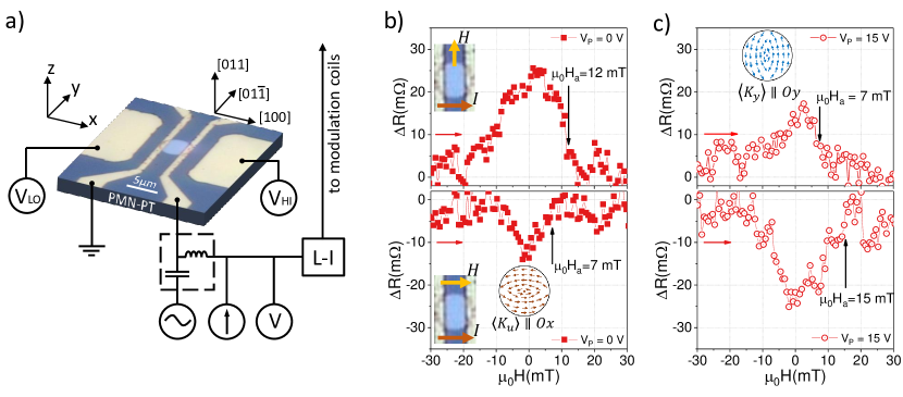
To detect the VC dynamics, we used a standard magnetotransport setup with rf capability [see Fig. 1(panel a)] for electrical detection of magnetization dynamics in single magnetic vortices at room temperature. The detection technique exploits the anisotropic magnetoresistance (AMR) effect, i.e., the resistance change induced by the relative angle between the direction of the electrical current and the net magnetization of a magnetic structure. An rf current injected through a bias-T into the microdisk device excites the VC gyrotropic dynamical mode, via the joint action of the spin-transfer torque and rf Oersted field, and thereby leads to a dynamical magnetoresistance oscillating at the excitation frequency. The time-averaged product of the rf current and the dynamical magnetoresistance –- which results in a rectified dc voltage –– is measured by a conventional homodyne detection scheme using a lock-in amplifier. When the excitation frequency matches the eigenfrequency of the gyrotropic mode, the resulting is enhanced due to the dynamical magnetoresistance increase associated with the resonant expansion of the VC gyration trajectory. To improve the signal-to-noise ratio, magnetic field modulation of the dynamical magnetoresistance at the lock-in reference frequency (here 1033 Hz) was used similar to Ramasubramanian et al. (2022); Ramasubramanian (2022). To allow for an electrical excitation of the piezoelectric PMN-PT substrate, a dc voltage is applied between the surface electrodes, as depicted in Fig. 1(panel a).
For the micromagnetic simulations, we use the GPU-accelerated MuMax3 software package Vansteenkiste et al. (2014) to simulate the magnetization dynamics in the CoFeB vortices under strain. Similar to Wagner et al. (2021); Iurchuk et al. (2021), the VC dynamics is excited by an in-plane rf magnetic field pulse with the amplitude = 2.5 mT and the cut-off frequency = 2 GHz. For each simulation, the time evolution of the magnetization is recorded for 200 ns with the time step of 50 ps, and the microwave-absorption power spectra are calculated by performing the Fourier transform of the time-dependent magnetization dynamics. We use the following CoFeB material parameters: saturation magnetization = 1100 kA/m (measured by vibrating sample magnetometry), exchange constant = 20 pJ/m3, and damping parameter = 0.008. For each disk diameter, we use 5530 nm3 cell sizes for the magnetization dynamics simulations, and a finer discretization into 555 nm3 cells, for the computation of the equilibrium energies.
III Results and discussion
III.1 Strain-dependent magnetoresistance
Fig. 1(panel b) shows the typical anisotropic magnetoresistance of the CoFeB disk with a diameter of 3.65 m measured for a dc current = 2 mA and at zero voltage applied to the PMN-PT. Top graph of Fig. 1(panel b) shows the magnetoresistance (MR) curve for the magnetic field applied perpendicular to the direction. Bottom graph in Fig. 1(panel b) shows the MR for , i.e. for . The magnetic field is swept from negative to positive saturation. For , when the field is increased from the negative saturation values (40mT) towards zero, we observe a resistance growth of 25 m (corresponding to the MR⟂ ratio of 0.015 % being a typical value for Fe-based alloys). This resistance increase indicates a nucleation of a vortex within the CoFeB disk. Further increase of the magnetic field leads to the VC shift towards the edge of the disk and, eventually, to the VC expulsion when the annihilation field is reached. Similarly, for , the resistance drop of 15 m (MR0.008%) is measured in the vicinity of =0, in agreement with the angular dependence of MR.
However, two notable observations can be made. First, a large asymmetry of the MR magnitudes for and , where the value of MR⟂ is almost twice higher as compared to MR∥. Second, a large difference in the vortex nucleation/annihilation fields is present, depending on the magnetic field orientation. From the magnetoresisance data, we estimate the annihilation field values = 12 mT and = 8 mT. This indicates an asymmetric magnetic configuration of the nucleated vortex, otherwise, in case of a radially symmetric vortex, a rather similar magnetoresistive response would be expected for all in-plane directions of the applied field. The distortion of the vortex configuration is attributed to the presence of the uniaxial magnetic anisotropy, typical for the sputtered CoFeB films Gladii et al. (2023). In our measurements, MR MR⟂ and , which indicates the presence of a non-zero net magnetic anisotropy along the , i.e. along the direction. The corresponding vortex configuration is sketched in the inset of the Fig. 1(panel b). We estimate the anisotropy constant from the difference between the annihilation fields and as . Using the measured values of and and the = 1110 kA/m (from the magnetometry measurements), we obtain 1.1 kJ/m3.
Fig. 1(panel c) shows the magnetoresistance curves of the same disk measured for the =2 mA, under = 15 V applied to the PMN-PT. We note a drastic qualitative difference between the MR curves measured with and without . Comparing the MR curves measured for , at = 0 and = 15 V [see top graphs in Fig. 1(b) and (c)], we observe two main effects, namely a reduction of the MR⟂ ratio from 0.015% to 0.01% and a decrease of the from 12 to 7 mT . On the other hand, for , an opposite effect is observed, i.e. increase of both MR∥ (from 0.008% to 0.015%) and (from 8 to 15 mT).
These voltage-induced effects are explained by the presence of a magnetoelastic anisotropy energy due to the electric-field induced strain, generated via converse piezoelectric effect in PMN-PT and transferred to the CoFeB microdisk. The magnetoelastic energy density is defined as , where = 50 ppm is the saturation magnetostriction of CoFeB, = 160 GPa is the CoFeB Young’s modulus and is the net strain along the direction. We introduce as effective uniaxial strain generated locally in the small area between the surface electrodes (see Fig. 1(panel a)). Based on the magnetoresistance measurements, we determine that , i.e. the generated strain is compressive along the direction. Indeed, the observed increase of the MR∥ and [see bottom graph in Fig. 1(panel c)] suggests that, under increasing strain, the net anisotropy decreases, in agreement with . Under compressive uniaxial strain, the magnetic vortex configuration is distorted, which is manifested as the contraction in the direction of the strain and the elongation in the direction perpendicular to the strain. Therefore, the compressive strain along the direction lowers the effective anisotropy in this direction and simultaneously increases the net anisotropy in the perpendicular in-plane direction, i.e along . This is consistent with the measured reduction of the MR⟂ and at = 15 V, and for the magnetic field perpendicular to the current. The vortex configuration corresponding to the strained state is schematically shown in the inset of Fig. 1(panel c). One has to note that, in our experiment, the electric field is applied along [100] crystallographic axis of the PMN-PT crystal and, therefore, the compressive strain is expected for a given crystallographic orientation of the PMN-PT crystal Wu et al. (2011).
III.2 Strain-controlled gyration dynamics
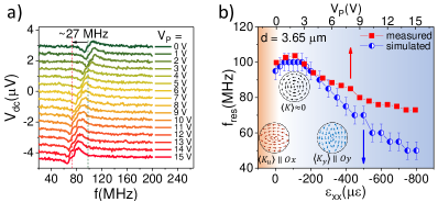
Fig. 2(a) shows the rectified spectra vs. rf current frequency for the CoFeB disk with 3.65 m diameter, measured at zero magnetic field and for different values of the voltage applied to the PMN-PT substrate. For all values, the measured resonances have a typical antisymmetric Lorentzian shape, associated with the dominant contribution of the rf Oersted field to the VC gyration dynamics Kim et al. (2013); Ramasubramanian et al. (2022). For = 0, = 100 MHz, in a good agreement with the analytically predicted value (112 MHz) by the Guslienko’s ”two-vortices” model Guslienko et al. (2002). We observe a gradual decrease of the gyrotropic frequency with increasing (i.e. with increasing piezostrain) attributed to the magnetoelastic anisotropy-induced softening of the restoring force spring constants Roy (2013b). For the voltage range used in our experiment ( 15 V), the maximum frequency downshift is 27 MHz (corresponding to 27 %) at 15 V, as compared to the initial value at 0 V.
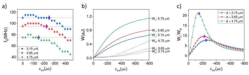
Fig. 2(b, red squares) shows the values of the gyrotropic frequency as a function of the . A detailed examination of the dependence reveals a non-monotonous behavior of the gyrotropic frequency, namely a small increase at low voltages ( 2 V), followed by a steady decrease for 3 V. To understand this behavior, we conducted micromagnetic simulations of the VC gyration dynamics as a function of the uniaxial strain . The corresponding dependence is plotted in Fig. 2(b, blue circles) and is in good agreement with the experimental for moderate values of the voltage 6 V, corresponding to the uniaxial compressive strain 350 . The comparison between the experimental and simulated allows for an estimation of the piezoelectrically generated strain per unit electric field E in the PMN-PT in the linear regime. We obtain –600 pm/V, in agreement with the typical values of the in-plane piezoelectric constants of the PMN-PT. An increased discrepancy between the experimental and simulated at high is related to the non-linear strain-voltage dependence in voltage range close to the ferroelectric saturation.
In Fig. 2(b, blue circles), three distinctive regions in the dependence can be differentiated: 75 , where increases; 100 150 , where is stable; and 175 , where decreases. Taking into account the net uniaxial anisotropy =1.1 kJ/m3 in the as-prepared CoFeB disk (see section III.1), these three regions can be associated with the anisotropy compensation region, where ; the zero anisotropy region, where ; and the anisotropy enhancement region, where . Indeed, when the compressive strain increases from 0 to 75 , the induced magnetoelastic anisotropy is aligned along the direction (i.e. perpendicular to the direction), and competes with the existing net anisotropy along (see the bottom left sketch in Fig. 2(b)). The shape of the vortex is, therefore, gradually modified towards the radially symmetric configuration. This manifests as the increase of the gyrotropic frequency due to the decrease of the average uniaxial anisotropy. When the strain-induced magnetoelastic anisotropy compensates the intrinsic anisotropy, the net in-plane anisotropy vanishes and the gyrotropic frequency reaches its maximum value, which corresponds to the gyrotropic frequency of the radially symmetric vortex (see the middle sketch in Fig. 2(b)). Further increase of the value leads to the enhancement of the net anisotropy along (see the bottom right sketch in Fig. 2(b)), accompanied by the reduction of the gyrotropic frequency .
Our measurements demonstrate an efficient way to achieve a significant modification of the vortex gyrotropic frequency by piezoelectric strains, generated locally with moderate voltages applied to the piezosubstrate.
III.3 Size-dependent frequency downshift. Role of the magnetoelastic and demagnetizing energies
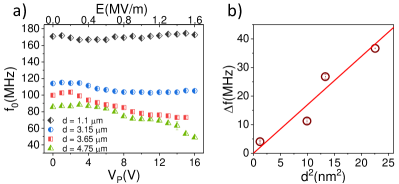
Fig. 3(a) shows the gyrotropic frequency vs. voltage , measured in the CoFeB disks with different diameters : 4.75, 3.65, 3.15, and 1.1 m. Together with the diameter-dependent gyrotropic frequency , we observe a clear dependence of the maximum frequency downshift on the device size. Here, is defined, for each disk diameter, as a difference between the gyrotropic frequency at and the minimum attainable under strain (at ). For = 1.1 m, the gyrotropic frequency weakly depends on the voltage showing a decrease from 171 MHz at zero strain to 166 MHz at = 5 V followed by a slight increase back to the original value at higher voltages. The device with = 3.15 m shows the drop of 12 MHz (corresponding to the relative decrease of 10.5 % ) from 114 MHz at down to 102 MHz for 9 V. The devices with larger diameters show progressively larger strain-induced frequency downshift, i.e. 27 MHz for = 3.65 m and 36 MHz for = 4.75 m, corresponding to 27 % and 45 %, respectively. Fig. 3(b) shows the vs. dependence with a quasi-linear increase of the frequency downshift with increased disk area.
To understand the observed size dependence, we calculated the values as a function of strain for different disk diameters [see Fig. 4(a)]. Here, the same magnetic parameters were used as for the simulated data of Fig. 2(b). For increased disk diameter, we observe a reduction of the critical strain, where the onset of the frequency decrease is observed. This suggests, that for larger disks, less magnetoelastic energy is needed to downshift the gyrotropic frequency. Note, that this effect does not depend on the magnetic anisotropy, and is present even for .
To further reveal the origin of the critical strain decrease for large disks, we calculated the equilibrium values of the magnetoelastic and demagnetizing energies as a function of the compressive strain [see Fig. 4(b,c)]. We exclude the exchange energy from the consideration due to its negligible value as compared to and for the given disk sizes. One can see, that for small values, the magnetoelastic energy dominates [see Fig. 4(b)], however the onset of the decrease, for the given disk diameter, coincides with the onset of the demagnetizing energy increase. Fig. 4(c) shows the ratio vs. for different disk sizes. Here, the values of the critical strain (marked with a diamond) correspond to the maximum values of i.e. to the onset of increase. This suggests that besides the magnetoelastic energy contribution, the observed size effects may be related to the increased demagnetizing energy due to the strain-induced distortion of the magnetization distribution in the vortex.
IV Conclusion
We demonstrated a large frequency tunability (up to 45%) in individual CoFeB disks accessed locally with low surface voltages (16 V) applied to the PMN-PT substrate. Piezostrain-induced tuning and magnetoresistive readout of the VC dynamics via microwave rectification measurements allows for an all-electrical operation of the designed microdevices. The observed decrease of the VC gyrotropic frequency is associated with the strain-induced magnetoelastic energy. We showed that the frequency tunability strongly depends on the magnetic disk size, with increased frequency shift for the disks with larger diameter. Micromagnetic simulations show that the observed size effects originate jointly from the increased magnetoelastic energy as well as from the enhanced demagnetizing energy, resulting from the strain-induced distortion of the vortex configuration. Our results show that electrically induced piezostrain offers an extra room for the frequency tunability of the VC dynamics in individual spintronic oscillators. In perspective, the frequency tunability for given strain magnitudes can be further enhanced by substituting CoFeB with large-magnetostriction materials (e.g. FexGa1-x, TbFe2, DyFe2, Terfenol-D, etc).
Acknowledgements.
Funded by the Deutsche Forschungsgemeinschaft (DFG, German Research Foundation) within the grant IU 5/2-1 (STUNNER) – project number 501377640. Support from the Nanofabrication Facilities Rossendorf (NanoFaRo) at the IBC is gratefully acknowledged. We thank Thomas Naumann for help with the CoFeB thin films growth. We acknowledge useful discussions with Ciarán Fowley on the low-heat microfabrication process details. We thank Ryszard Narkowicz for help with the implementation of the field modulation in the experimental setup.References
- Aharoni (1990) A. Aharoni, Journal of Applied Physics 68, 2892 (1990), publisher: American Institute of Physics.
- Usov and Peschany (1993) N. A. Usov and S. E. Peschany, Journal of Magnetism and Magnetic Materials 118, L290 (1993).
- Shinjo et al. (2000) T. Shinjo, T. Okuno, R. Hassdorf, K. Shigeto, and T. Ono, Science 289, 930 (2000), publisher: American Association for the Advancement of Science.
- Guslienko et al. (2002) K. Y. Guslienko, B. A. Ivanov, V. Novosad, Y. Otani, H. Shima, and K. Fukamichi, Journal of Applied Physics 91, 8037 (2002).
- Lebrun et al. (2014) R. Lebrun, N. Locatelli, S. Tsunegi, J. Grollier, V. Cros, F. Abreu Araujo, H. Kubota, K. Yakushiji, A. Fukushima, and S. Yuasa, Phys. Rev. Appl. 2, 061001 (2014).
- Lebrun et al. (2015) R. Lebrun, A. Jenkins, A. Dussaux, N. Locatelli, S. Tsunegi, E. Grimaldi, H. Kubota, P. Bortolotti, K. Yakushiji, J. Grollier, A. Fukushima, S. Yuasa, and V. Cros, Phys. Rev. Lett. 115, 017201 (2015).
- Litvinenko et al. (2020) A. Litvinenko, V. Iurchuk, P. Sethi, S. Louis, V. Tyberkevych, J. Li, A. Jenkins, R. Ferreira, B. Dieny, A. Slavin, and U. Ebels, Nano Letters 20, 6104 (2020).
- Litvinenko et al. (2021) A. Litvinenko, P. Sethi, C. Murapaka, A. Jenkins, V. Cros, P. Bortolotti, R. Ferreira, B. Dieny, and U. Ebels, Phys. Rev. Appl. 16, 024048 (2021).
- Dussaux et al. (2010) A. Dussaux, B. Georges, J. Grollier, V. Cros, A. V. Khvalkovskiy, A. Fukushima, M. Konoto, H. Kubota, K. Yakushiji, S. Yuasa, K. A. Zvezdin, K. Ando, and A. Fert, Nature Communications 1, 1 (2010).
- Ramasubramanian et al. (2022) L. Ramasubramanian, V. Iurchuk, S. Sorokin, O. Hellwig, and A. M. Deac, Physical Review B 106, 214413 (2022), publisher: American Physical Society.
- Sluka et al. (2015) V. Sluka, A. Kákay, A. M. Deac, D. E. Bürgler, C. M. Schneider, and R. Hertel, Nature Communications 6, 6409 (2015).
- Ramasubramanian et al. (2020) L. Ramasubramanian, A. Kákay, C. Fowley, O. Yildirim, P. Matthes, S. Sorokin, A. Titova, D. Hilliard, R. Böttger, R. Hübner, S. Gemming, S. E. Schulz, F. Kronast, D. Makarov, J. Fassbender, and A. Deac, ACS Applied Materials & Interfaces 12, 27812 (2020), publisher: American Chemical Society.
- Roy et al. (2012) K. Roy, S. Bandyopadhyay, and J. Atulasimha, Journal of Applied Physics 112, 023914 (2012), publisher: American Institute of Physics.
- Roy (2013a) K. Roy, Applied Physics Letters 103, 173110 (2013a).
- Iurchuk et al. (2014) V. Iurchuk, B. Doudin, and B. Kundys, Journal of Physics: Condensed Matter 26, 292202 (2014).
- Iurchuk et al. (2015) V. Iurchuk, B. Doudin, J. Bran, and B. Kundys, Physics Procedia 75, 956 (2015).
- Wang et al. (2017) Q. Wang, X. Li, C.-Y. Liang, A. Barra, J. Domann, C. Lynch, A. Sepulveda, and G. Carman, Applied Physics Letters 110, 102903 (2017), publisher: American Institute of Physics.
- Schneider et al. (2019) J. D. Schneider, Q. Wang, Y. Li, A. C. Chavez, J.-Z. Hu, and G. Carman, Journal of Applied Physics 126, 163903 (2019).
- Iurchuk et al. (2023) V. Iurchuk, J. Bran, M. Acosta, and B. Kundys, Applied Physics Letters 122, 072404 (2023), publisher: American Institute of Physics.
- Parkes et al. (2014) D. E. Parkes, R. Beardsley, S. Bowe, I. Isakov, P. A. Warburton, K. W. Edmonds, R. P. Campion, B. L. Gallagher, A. W. Rushforth, and S. A. Cavill, Applied Physics Letters 105, 062405 (2014).
- Gilbert et al. (2016) I. Gilbert, A. C. Chavez, D. T. Pierce, J. Unguris, W.-Y. Sun, C.-Y. Liang, and G. P. Carman, Applied Physics Letters 109, 162404 (2016).
- Ghidini et al. (2020a) M. Ghidini, R. Pellicelli, R. Mansell, D. Pesquera, B. Nair, X. Moya, S. Farokhipoor, F. Maccherozzi, C. H. W. Barnes, R. P. Cowburn, S. S. Dhesi, and N. D. Mathur, Journal of Physics D: Applied Physics 53, 434003 (2020a), publisher: IOP Publishing.
- Ghidini et al. (2020b) M. Ghidini, R. Mansell, R. Pellicelli, D. Pesquera, B. Nair, X. Moya, S. Farokhipoor, F. Maccherozzi, C. H. W. Barnes, R. P. Cowburn, S. S. Dhesi, and N. D. Mathur, Nanoscale 12, 5652 (2020b), publisher: The Royal Society of Chemistry.
- Li et al. (2017) Q. Li, A. Tan, A. Scholl, A. T. Young, M. Yang, C. Hwang, A. T. N’Diaye, E. Arenholz, J. Li, and Z. Q. Qiu, Applied Physics Letters 110, 262405 (2017).
- Ostler et al. (2015) T. Ostler, R. Cuadrado, R. Chantrell, A. Rushforth, and S. Cavill, Physical Review Letters 115, 067202 (2015).
- Roy (2013b) P. E. Roy, Applied Physics Letters 102, 162411 (2013b).
- Finizio et al. (2017) S. Finizio, S. Wintz, E. Kirk, A. K. Suszka, S. Gliga, P. Wohlhüter, K. Zeissler, and J. Raabe, Physical Review B 96, 054438 (2017).
- Filianina et al. (2019) M. Filianina, L. Baldrati, T. Hajiri, K. Litzius, M. Foerster, L. Aballe, and M. Kläui, Applied Physics Letters 115, 062404 (2019).
- Zhang et al. (2008) S. Zhang, S.-M. Lee, D.-H. Kim, H.-Y. Lee, and T. R. Shrout, Journal of the American Ceramic Society 91, 683 (2008), _eprint: https://onlinelibrary.wiley.com/doi/pdf/10.1111/j.1551-2916.2007.02190.x.
- Wu et al. (2011) T. Wu, P. Zhao, M. Bao, A. Bur, J. L. Hockel, K. Wong, K. P. Mohanchandra, C. S. Lynch, and G. P. Carman, Journal of Applied Physics 109, 124101 (2011), publisher: American Institute of Physics.
- Guo et al. (2002) Y. Guo, H. Luo, K. Chen, H. Xu, X. Zhang, and Z. Yin, Journal of Applied Physics 92, 6134 (2002), publisher: American Institute of Physics.
- Guo et al. (2003) Y. Guo, H. Luo, D. Ling, H. Xu, T. He, and Z. Yin, Journal of Physics: Condensed Matter 15, L77 (2003).
- Makhort et al. (2018) A. S. Makhort, F. Chevrier, D. Kundys, B. Doudin, and B. Kundys, Physical Review Materials 2, 012401 (2018), publisher: American Physical Society.
- Jubert and Allenspach (2004) P.-O. Jubert and R. Allenspach, Physical Review B 70, 144402 (2004).
- Ramasubramanian (2022) L. Ramasubramanian, Tunable magnetic vortex dynamics, Ph.D. thesis, Technische Universität Chemnitz (2022).
- Vansteenkiste et al. (2014) A. Vansteenkiste, J. Leliaert, M. Dvornik, M. Helsen, F. Garcia-Sanchez, and B. Van Waeyenberge, AIP Advances 4, 107133 (2014), publisher: American Institute of Physics.
- Wagner et al. (2021) K. Wagner, L. Körber, S. Stienen, J. Lindner, M. Farle, and A. Kákay, IEEE Magnetics Letters 12, 1 (2021), conference Name: IEEE Magnetics Letters.
- Iurchuk et al. (2021) V. Iurchuk, L. Körber, A. M. Deac, J. Faßbender, J. Lindner, and A. Kákay, Journal of Physics D: Applied Physics 54, 475002 (2021), publisher: IOP Publishing.
- Gladii et al. (2023) O. Gladii, R. Salikhov, O. Hellwig, H. Schultheiss, J. Lindner, and R. A. Gallardo, Phys. Rev. B 107, 104419 (2023).
- Kim et al. (2013) J.-S. Kim, M. Kläui, M. V. Fistul, J. Yoon, C.-Y. You, R. Mattheis, C. Ulysse, and G. Faini, Physical Review B 88, 064402 (2013), publisher: American Physical Society.