Substantial reduction of write-error rate for voltage-controlled magnetoresistive random access memory by in-plane demagnetizing field and voltage-induced negative out-of-plane anisotropy field
Abstract
Voltage-controlled magnetoresistive random access memory (VC-MRAM) based on voltage-induced dynamic switching in magnetic tunnel junctions (MTJs) is a promising ultimate non-volatile memory with ultralow power consumption. However, the dynamic switching in a conventional MTJ is accompanied by a relatively high write error rate (WER), hindering the reliable operation of VC-MRAM. Here, we propose a reliable writing scheme using the in-plane demagnetizing field (IDF) and voltage-induced negative out-of-plane anisotropy field (NOAF). Numerical simulations based on macrospin model demonstrate that the voltage-induced NOAF modifies the switching dynamics and increases the torque due to the IDF, thereby reducing the switching time. The IDF and voltage-induced NOAF also reduce the mean energy difference between the magnetization direction at the end of the pulse and the equilibrium direction. As a result, an appropriate combination of the IDF and voltage-induced NOAF reduces the WER by one order of magnitude compared with that of the dynamic switching in a conventional MTJ.
keywords:
Spintronics , Voltage controlled magnetismPACS:
75.30.Gw , 75.70.Ak , 75.78.-n , 85.75.-d1 Introduction
Voltage-controlled magnetoresistive random-access memory (VC-MRAM) [1, 2, 3, 4, 5, 6, 7, 8, 9, 10, 11, 12, 13, 14] has attracted considerable attention as an emerging ultralow-power non-volatile memory. The writing scheme of VC-MRAM is based on the voltage control of magnetic anisotropy (VCMA) in a magnetic tunnel junction (MTJ) [15, 16, 17] with perpendicular magnetization (see Fig. 1(a)). Without applied voltage, the magnetization in the FL is aligned nearly in the out-of-plane direction due to the perpendicular magnetic anisotropy (PMA) at the interface. Application of the voltage pulse (see Fig. 1(b)) reduces the PMA through the VCMA effect [1, 2, 3, 4, 5], inducing the precession of the magnetization around the magnetic field applied in the in-plane direction [18].
In the conventional dynamic switching scheme [6, 7, 8, 9, 10, 11, 12, 13, 14], the circular cylinder shaped MTJ nanopillar is used as shown Fig. 1(c). The effective out-of-plane anisotropy constant, , is reduced to zero by the voltage pulse, as shown in Fig. 1(d), where and denote the effective out-of-plane anisotropy at and , respectively. The WER strongly depends on the the pulse duration, , as shown in Fig. 1(e). The WER is minimized when is approximately the half of the precession period. The VC-MRAM has a clear advantage that its energy consumption to write a bit is one hundred times smaller than that of the spin-transfer-torque (STT)-MRAM [19, 11]. However, the WER of the VC-MRAM () [14] is considerably higher than that of the STT-MRAM () [20]. To reduce the WER of VC-MRAM, very precise control of the pulse duration is necessary. Notably, such precise control of the pulse duration is difficult in large-scale integrated circuits due to circuit delay.
Another switching scheme of VC-MRAM called heavily damped switching [21, 22] is schematically shown in Fig. 1(f). The in-plane magnetic field is applied parallel to the minor axis of the elliptical MTJ. The Gilbert damping constant, , is assumed to be large enough to suppress the precession back to the initial direction. The effective out-of-plane anisotropy constant is reduced by the voltage pulse but remains positive as shown in Fig. 1(g). Although the minimum WER of the heavily damped switching is higher than that of the conventional dynamic switching due to the large , the heavily damped switching has an advantage that the WER is insensitive to the pulse duration as shown in Fig. 1(h). Therefore, the precise control of the pulse duration is unnecessary. The heavily damped switching is suited for some special applications such as error-tolerant machine learning for image recognition and object detection [23].

For cache applications, it is necessary to develop a reliable writing scheme, whose WER is very low. In this paper, we propose a new reliable switching scheme using the in-plane demagnetizing field (IDF) and voltage-induced negative out-of-plane anisotropy field (NOAF) (Figs. 1(i) and (j)). We calculated the WER by solving the Langevin equation of the macrospin model, demonstrating that the WER is reduced by one order of magnitude (Fig. 1(k)) compared with that of the dynamic switching in a conventional MTJ (Fig. 1(e)). The mechanism of the reduction of the WER is discussed by analyzing the switching dynamics, torques, and distribution of the magnetizations at the end of the pulse.
2 Model and method
We consider an elliptical cylinder shaped MTJ nanopillar, shown in Figs. 1(a) and (i). The lateral size of the nanopillar is assumed to be so small that the magnetization dynamics can be described by the macrospin model. The direction of magnetization in the FL is represented by the unit vector , , , , ), where and are the polar and azimuthal angles, respectively. The -axis is parallel to the major axis of the ellipse. The external in-plane magnetic field, , is applied in the positive -direction. The magnetization in the reference layer is fixed to align with the positive -direction.
The energy density of the FL is given by [24]
| (1) | |||||
where, the demagnetization coefficients , , and are assumed to satisfy , is the vacuum permeability, is the saturation magnetization of the FL, and , is the external in-plane magnetic field. Without loss of generality, we assume that . The index of the IDF, is given by [25]. is the uniaxial out-of-plane anisotropy constant. The value of can be controlled by applying a bias voltage through the VCMA effect, as shown in Fig. 1(j). Hereafter, represents the effective out-of-plane anisotropy constant defined by , and indicates the value of during the voltage pulse. Note that, when and is negative (positive), the magnetization is relaxed to in-plane (perpendicular) state. We call the field induced by the negative effective out-of-plane anisotropy as negative out-of-plane anisotropy field (NOAF).
The magnetization dynamics are simulated using the following Langevin equation [26]:
| (2) |
where is time, is the gyromagnetic ratio, and is the Gilbert damping constant. The thermal agitation field, , satisfies the following relations: and , where represents the statistical mean, , is the Boltzmann constant, is the temperature, is the volume of the FL volume, and is Kronecker’s delta. The effective magnetic field, , is defined as
| (3) |
The following parameters are assumed in simulations. The Gilbert damping constant is set as , the saturation magnetization as kA/m, the effective anisotropy constant at as kJ/m3, and temperature as K. Hereafter, the superscript “(0)” denotes any quantities obtained at . The thickness and area of the FL are nm and nm2, respectively. The aspect ratio of the ellipse is assumed to be . We also performed simulations for circular MTJ, , for comparison.
The initial state of the simulation is prepared by relaxing the magnetization at K with for 10 ns from the equilibrium direction at K with [27]. Then, the magnetization dynamics at K are calculated under a voltage pulse applied over a duration of (Fig. 1(b)). During the duration of the pulse, is reduced to through the VCMA effect (Fig. 1(j)). After the pulse, the anisotropy constant is increased to the initial value of , and there the magnetization is relaxed at K for 10 ns. The success or failure of switching is determined by the sign of after 10 ns of relaxation. The demagnetization coefficient of the FL is , , [28], and the magnitude of the IDF is kA/m) Oe [25]. The WERs are calculated from trials.
3 Results
3.1 Upper and lower boundaries of for dynamic switching
The equilibrium magnetization direction at and is obtained by minimizing the energy density at , . Figure 2(a) shows the contour plot of at Oe on the - plane, where the equilibrium directions, , , , 0.258, , are indicated by the open circles. The application of a bias voltage reduces the anisotropy constants from to and destabilizes the initial state. Under appropriate conditions of and , the precessional motion of magnetization around the effective magnetic field is induced [29]. As shown in Fig. 2(b), at kJ/m3, two equilibrium directions indicated by the open circles are connected by the closed thick gray contour. Therefore, using the precession when the pulse yielding kJ/m3 is applied for the half period of precession, the direction of the magnetization can be switched from one equilibrium direction to the other.

The analytical expression of the upper and lower boundaries of for dynamic switching is obtained by analyzing the stability of the equilibrium direction [29, 21, 22]. For the small applied field satisfying , the lower boundary is given by
| (4) |
where
| (5) |
The upper boundary is given by [22]
| (6) |
where . For the external magnetic field satisfying , the lower boundary is the same as Eq. (4) while the upper boundary becomes [22]
| (7) |
Increasing the external magnetic field reduces the energy barrier between the two equilibrium directions. When the external magnetic field is larger than , the energy barrier vanishes and system has one equilibrium direction at . The information cannot be stored as the direction of the magnetization under such a strong magnetic field.
3.2 , , and dependence of WER
Figures 3(a) and 3(b) shows examples of the WER of the circular and elliptical MTJs. The thickness and area of the FL is the same for both circular and elliptical MTJs. The demagnetizing coefficient for the circular MTJ is and [28]. The other parameters, except for and , are the same for all calculations. We calculated the WER for wide range of and and found that the optimal value of (, ) is (400 Oe, 0 kJ/m3) for the circular MTJ and (800 Oe, -60 kJ/m3) for the elliptical MTJ.

The WER of the circular MTJ exhibits the minimum value of (WER) at ns, as shown in Fig. 3(a). The effective field during the precession comprises only the external field, and the optimal value of the pulse duration is approximately the half of the precession period, i.e., = ns. Note that, in the circular MTJ with and the optimal , the half of the precession period is regardless of the initial direction of magnetization which is thermally fluctuated. Therefore, the distribution of the magnetization direction is kept small during the precession, and subsequently WER is minimized [12]. However, in the elliptical MTJ with , this method cannot be applied.
The WER of the elliptical MTJ for exhibits a minimum value of (WER) at ns. The WER is lowered by decreasing . In the case of kJ/m3, (WER) is obtained at ns. This optimal is about the half of the precession period, and is shorter than at Oe, 0.23 ns. The precession period is shortened by IDF and NOAF. Note that IDF is induced by the elliptical-cylinder shape, and NOAF by the negative can be obtained by the increase of bias voltage and/or the VCMA effect. The occurrence of NOAF can be confirmed with the optimal which is shorter than at the applied .
The results show that the appropriate combination of the IDF and the voltage-induced NOAF is effective for reducing the WER. The mechanism of the reduction of the switching time by IDF and voltage-induced NOAF is further discussed in Sec. 4.

Figure 4(a) shows the dependence of (WER)min which is the minimum value of WER obtained by minimizing the WER with respect to . The red squares connected with the red lines represent the results for the circular MTJ at Oe. The blue circles connected with the blue lines represent the results for elliptical MTJ at Oe. For large positive , the magnetization does not precess, and the WER is approximately unity. In the limit of large negative , WER is 0.5. This is because the magnetization precesses around -axis during the pulse. After the pulse, the magnetization relaxes to the two equilibrium directions with equal probability.
The WER is a convex function of , and the lower and upper bounds of for dynamic switching are given by Eqs. (4), (3.1), and (7). For circular MTJ at Oe, kJ/m3 and kJ/m3. The lower and upper bounds for dynamic switching of the elliptical MTJ are kJ/m3 and kJ/m3, respectively. The region for dynamic switching is spread and shifts to the negative by the IDF or ellipticity as shown in Fig. 4(a). As a result, the elliptical MTJ can be used in wider range of or than the circular MTJ.
Figure 4(b) shows dependence of [WER]min which is the minimum value of (WER)min in the dependence. The red squares connected with red lines represent the results for circular MTJ at kJ/m3. The blue circles connected with blue lines represent the results for elliptical MTJ at kJ/m3. For both MTJs, the [WER]min is a convex function of . The decrease of [WER]min with increase of in the small region is due to the decrease of the precession period or the switching time. The increase of the WER with increase of in the large region is due to the decrease of energy barrier between the two equilibrium directions. In the absence of the external field, the energy barrier between , , , 0, ) and (0, 1, 0) in the elliptical MTJ is higher than that in the circular MTJ because of the in-plane demagnetizing field. The enhanced energy barrier in the elliptical MTJ can endure large in-plane , that is, the initial state is stable even at large in the elliptical MTJ [22]. Therefore, the optimal value of that minimize [WER]min of the elliptical MTJ (800 Oe) is larger than that of the circular MTJ (400 Oe).
In the A, and dependencies of [WER]min are shown. In the elliptical MTJ, the optimal value of at and 0.05 are slightly smaller than that at , but it is larger than that in the circular MTJs.
4 Discussions
As shown in Figs. 3(a) and (b), the optimal pulse duration of the elliptical MTJ with kJ/m3 (0.20 ns) is considerably shorter than the elliptical MTJ with kJ/m3 (0.31 ns) and the circular MTJ (0.43 ns). The short switching time has the merit of suppressing errors due to the thermal agitation field during the pulse. To understand the mechanism of the reduction of the switching time by IDF and voltage-induced NOAF, we plot the time evolution of the magnetization at K and torque of the elliptical MTJ in Figs. 5(a) and 5(b).
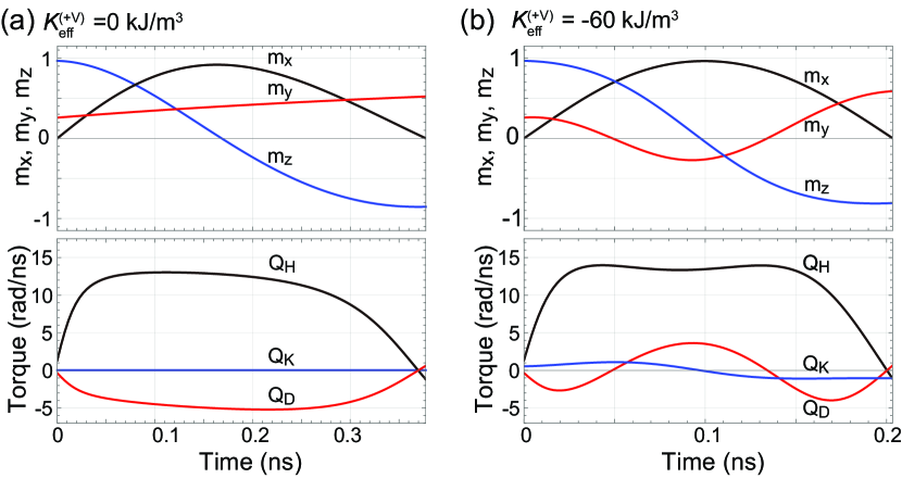
The top panel of Fig. 5(a) shows the time evolution of (black), (red), and (blue) of the elliptical MTJ under the pulse yielding kJ/m3. The origin of the horizontal axis is set to the beginning of the pulse. Starting from the equilibrium direction with , the magnetization precesses around the external field and reaches the direction with at 0.38 ns. Due to the damping and the IDF the trajectory is not a semicircle but a semispiral, where monotonically increases with time.
In the bottom panel Fig. 5(a), we plot the time evolution of the component of the torque due to the applied field, (black), the IDF, (red), and the effective out-of-plane anisotropy field, (blue). The torques are defined by the equation of motion of as
| (8) |
where
| (9) |
| (10) |
| (11) |
and is the dimensionless time defined as
| (12) |
As shown in the bottom panel Fig. 5(a), accelerates the switching dynamics, while decelerates the switching dynamics. is zero because kJ/m3. Note that the deceleration of the switching dynamics by the negative increases switching time and therefore WER.
The switching dynamics considerably changes when is reduced down to -60 kJ/m3 as shown in the top panel of Fig. 5(b). The -component of the magnetization, , oscillates and becomes negative around 0.1 ns. The switching time is as small as 0.20 ns, which is almost half of that for kJ/m3. The reduction of the switching time is caused by the positive around 0.1 ns. The results shown in Fig. 5(b) demonstrate that the NOAF induces the rotation of around -axis, making negative. Then, the in-plane anisotropy field, that is IDF, rotates around the -axis, thereby accelerating the switching dynamics and reducing WER in the elliptical MTJ. Note that, in the circular MTJ, shown in Eq. 10 cannot accelerate the switching dynamics because .
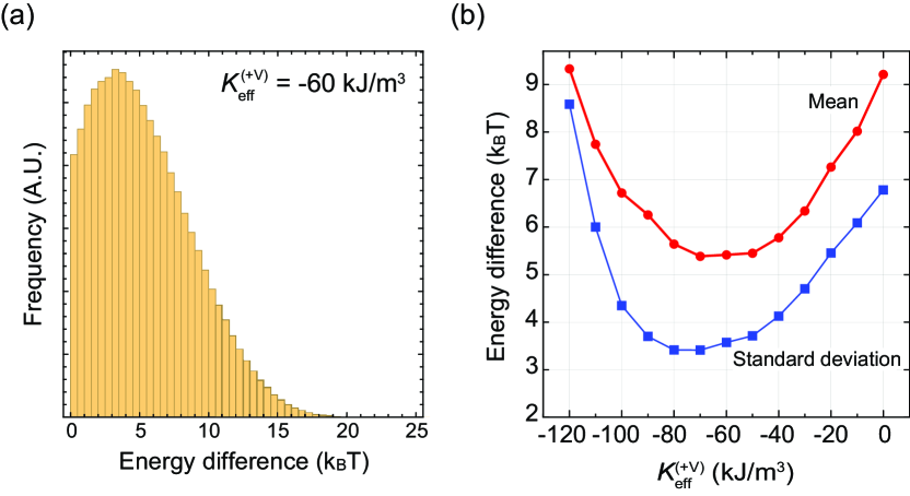
Figure 6(a) shows the distribution of energy difference between the magnetization directions at the end of the pulse and the equilibrium direction in the unit of . The parameters are set to the optimal values, kJ/m3, 800 Oe, and 0.20 ns. The shift of the peak of the distribution from zero is caused by Gilbert damping. The mean and standard deviation are 5.6 and 3.4 , respectively. Figure 6(b) shows the dependence of the mean (red circles) and standard deviation (blue squares) of the energy difference between the magnetization directions at the end of the pulse and the equilibrium direction. The external in-plane magnetic field is set as 800 Oe. At each , is set to the optimal values that minimize the WER there. The mean of the energy difference is minimized around kJ/m3 which is the optimal value at with the WER is minimized. The standard deviation of the energy difference is minimized at kJ/m3.
The standard deviation is a measure of how large the distribution is spread during the pulse and should decrease with decrease of the switching time. Moreover, the mean is a measure of how close the magnetization at the end of the pulse is to the equilibrium direction. The mean depends not only on the switching time but also on the details of torques during the pulse. Therefore, the value of that minimizes the mean should not be the same as that minimizes the standard deviation. However, the results show that both mean and standard deviation are minimized at close to the optimal value. The appropriate combination of the IDF and voltage-induced NOAF reduces not only the switching time but also the energy difference between the magnetization directions at the end of the pulse and the equilibrium direction. As a result, the WER is minimized at the optimal value of , , and .
5 Conclusions
We theoretically analyzed the WER of voltage-induced switching for the VC-MRAM and showed that the appropriate combination of the in-plane demagnetizing field and voltage-induced negative out-of-plane anisotropy field reduces the WER by one order of magnitude compared with that of the dynamic switching in a conventional MTJ. The mechanism of WER reduction is discussed based on the magnetization dynamics at K and the distribution of the energy difference between the magnetization directions at the end of the pulse and the equilibrium direction at K. Furthermore, we show that the reduction of the switching time and the mean of the energy difference by the in-plane demagnetizing field and voltage-induced negative out-of-plane anisotropy field causes the reduction of WER. The results provide a guide for designing a reliable VC-MRAM.
6 Acknowledgements
This study is partly based on results obtained from a project, JPNP16007, commissioned by the New Energy and Industrial Technology Development Organization (NEDO), Japan.
Appendix A dependence of the WER
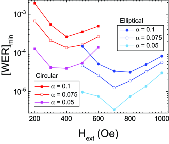
Figure 7 shows and dependencies of [WER]min. For both the circular MTJ and the elliptical MTJ, [WER]min decreases with decrease of because the magnitude of the thermal agitation field is proportional to .
In the circular MTJ with , 0.075 and 0.05, the minimum [WER]min is yielded by the optimal conditions, kJ/m3 and Oe. In the elliptical MTJ with , (0.075 and 0.05,) the minimum [WER]min is yielded by the optimal conditions, kJ/m3, (-60 kJ/m3 and -60 kJ/m3,) and Oe, (700 Oe and 700 Oe,) respectively. The elliptical MTJ with smaller does not require Oe where the reduction of energy barrier and the stability of the initial states are more serious than the reduction of the switching time.
References
-
[1]
M. Weisheit, S. Fhler, A. Marty, Y. Souche, C. Poinsignon,
D. Givord, Electric field-induced modification of magnetism in thin-film
ferromagnets, Science 315 (5810) (2007) 349–351.
doi:10.1126/science.1136629.
URL http://science.sciencemag.org/content/315/5810/349 -
[2]
T. Maruyama, Y. Shiota, T. Nozaki, K. Ohta, N. Toda, M. Mizuguchi, A. A.
Tulapurkar, T. Shinjo, M. Shiraishi, S. Mizukami, Y. Ando, Y. Suzuki, Large
voltage-induced magnetic anisotropy change in a few atomic layers of iron,
Nat. Nano. 4 (3) (2009) 158–161.
doi:10.1038/nnano.2008.406.
URL http://www.nature.com/nnano/journal/v4/n3/full/nnano.2008.406.html -
[3]
C.-G. Duan, J. P. Velev, R. F. Sabirianov, Z. Zhu, J. Chu, S. S. Jaswal, E. Y.
Tsymbal, Surface magnetoelectric effect in ferromagnetic metal films, Phys.
Rev. Lett. 101 (13) (2008) 137201.
doi:10.1103/PhysRevLett.101.137201.
URL http://link.aps.org/doi/10.1103/PhysRevLett.101.137201 -
[4]
K. Nakamura, R. Shimabukuro, Y. Fujiwara, T. Akiyama, T. Ito, A. J. Freeman,
Giant modification of the magnetocrystalline anisotropy in transition-metal
monolayers by an external electric field, Phys. Rev. Lett. 102 (18) (2009)
187201.
doi:10.1103/PhysRevLett.102.187201.
URL http://link.aps.org/doi/10.1103/PhysRevLett.102.187201 -
[5]
M. Tsujikawa, T. Oda, Finite electric field effects in the large perpendicular
magnetic anisotropy surface Pt/Fe/Pt(001): A first-principles study,
Phys. Rev. Lett. 102 (24) (2009) 247203.
doi:10.1103/PhysRevLett.102.247203.
URL http://link.aps.org/doi/10.1103/PhysRevLett.102.247203 -
[6]
M. Endo, S. Kanai, S. Ikeda, F. Matsukura, H. Ohno, Electric-field effects on
thickness dependent magnetic anisotropy of sputtered
MgO/Co40Fe40B20/Ta structures, Appl. Phys. Lett.
96 (21) (2010) 212503.
doi:10.1063/1.3429592.
URL http://aip.scitation.org/doi/10.1063/1.3429592 -
[7]
Y. Shiota, T. Nozaki, F. Bonell, S. Murakami, T. Shinjo, Y. Suzuki, Induction
of coherent magnetization switching in a few atomic layers of FeCo using
voltage pulses, Nat. Mater. 11 (1) (2012) 39–43.
doi:10.1038/nmat3172.
URL http://www.nature.com/nmat/journal/v11/n1/full/nmat3172.html -
[8]
Y. Shiota, S. Miwa, T. Nozaki, F. Bonell, N. Mizuochi, T. Shinjo, H. Kubota,
S. Yuasa, Y. Suzuki, Pulse voltage-induced dynamic magnetization switching in
magnetic tunneling junctions with high resistance-area product, Appl. Phys.
Lett. 101 (10) (2012) 102406.
doi:10.1063/1.4751035.
URL http://aip.scitation.org/doi/10.1063/1.4751035 -
[9]
S. Kanai, M. Yamanouchi, S. Ikeda, Y. Nakatani, F. Matsukura, H. Ohno, Electric
field-induced magnetization reversal in a perpendicular-anisotropy
CoFeB-MgO magnetic tunnel junction, Appl. Phys. Lett. 101 (12)
(2012) 122403.
doi:10.1063/1.4753816.
URL http://aip.scitation.org/doi/10.1063/1.4753816 -
[10]
Y. Shiota, T. Nozaki, S. Tamaru, K. Yakushiji, H. Kubota, A. Fukushima,
S. Yuasa, Y. Suzuki, Evaluation of write error rate for voltage-driven
dynamic magnetization switching in magnetic tunnel junctions with
perpendicular magnetization, Appl. Phys. Express 9 (1) (2016) 013001.
doi:10.7567/APEX.9.013001.
URL http://iopscience.iop.org/article/10.7567/APEX.9.013001/meta -
[11]
C. Grezes, F. Ebrahimi, J. G. Alzate, X. Cai, J. A. Katine, J. Langer,
B. Ocker, P. Khalili Amiri, K. L. Wang, Ultra-low switching energy and
scaling in electric-field-controlled nanoscale magnetic tunnel junctions with
high resistance-area product, Appl. Phys. Lett. 108 (1) (2016) 012403.
doi:10.1063/1.4939446.
URL http://aip.scitation.org/doi/abs/10.1063/1.4939446 -
[12]
Y. Shiota, T. Nozaki, S. Tamaru, K. Yakushiji, H. Kubota, A. Fukushima,
S. Yuasa, Y. Suzuki, Reduction in write error rate of voltage-driven dynamic
magnetization switching by improving thermal stability factor, Appl. Phys.
Lett. 111 (2) (2017) 022408.
doi:10.1063/1.4990680.
URL http://aip.scitation.org/doi/10.1063/1.4990680 -
[13]
T. Yamamoto, T. Nozaki, Y. Shiota, H. Imamura, S. Tamaru, K. Yakushiji,
H. Kubota, A. Fukushima, Y. Suzuki, S. Yuasa, Thermally induced
precession-orbit transition of magnetization in voltage-driven magnetization
switching, Phys. Rev. Applied 10 (2) (2018) 024004.
doi:10.1103/PhysRevApplied.10.024004.
URL https://link.aps.org/doi/10.1103/PhysRevApplied.10.024004 -
[14]
T. Yamamoto, T. Nozaki, H. Imamura, Y. Shiota, S. Tamaru, K. Yakushiji,
H. Kubota, A. Fukushima, Y. Suzuki, S. Yuasa, Improvement of write error rate
in voltage-driven magnetization switching, J. Phys. D: Appl. Phys. 52 (16)
(2019) 164001.
doi:10.1088/1361-6463/ab03c2.
URL https://doi.org/10.1088/1361-6463/ab03c2 -
[15]
S. Yuasa, T. Nagahama, A. Fukushima, Y. Suzuki, K. Ando, Giant room-temperature
magnetoresistance in single-crystal Fe/MgO/Fe magnetic tunnel
junctions, Nat. Mater. 3 (12) (2004) 868–871.
doi:10.1038/nmat1257.
URL http://www.nature.com/nmat/journal/v3/n12/full/nmat1257.html -
[16]
S. S. P. Parkin, C. Kaiser, A. Panchula, P. M. Rice, B. Hughes, M. Samant,
S.-H. Yang, Giant tunnelling magnetoresistance at room temperature with MgO
(100) tunnel barriers, Nat. Mater. 3 (12) (2004) 862–867.
doi:10.1038/nmat1256.
URL http://www.nature.com/nmat/journal/v3/n12/full/nmat1256.html -
[17]
D. D. Djayaprawira, K. Tsunekawa, M. Nagai, H. Maehara, S. Yamagata,
N. Watanabe, S. Yuasa, Y. Suzuki, K. Ando, 230% room-temperature
magnetoresistance in CoFeB/MgO/CoFeB magnetic tunnel junctions, Appl.
Phys. Lett. 86 (9) (2005) 092502.
doi:10.1063/1.1871344.
URL http://scitation.aip.org/content/aip/journal/apl/86/9/10.1063/1.1871344 -
[18]
C. Davies, K. Prabhakara, M. D. Davydova, K. A. Zvezdin, T. B. Shapaeva,
S. Wang, A. K. Zvezdin, A. Kirilyuk, T. Rasing, A. V. Kimel, Anomalously
damped heat-assisted route for precessional magnetization reversal in an iron
garnet, Phys. Rev. Lett. 122 (2) (2019) 027202.
doi:10.1103/PhysRevLett.122.027202.
URL https://link.aps.org/doi/10.1103/PhysRevLett.122.027202 -
[19]
S. Kanai, F. Matsukura, H. Ohno, Electric-field-induced magnetization switching
in CoFeB/MgO magnetic tunnel junctions with high junction resistance,
Appl. Phys. Lett. 108 (19) (2016) 192406.
doi:10.1063/1.4948763.
URL https://aip.scitation.org/doi/10.1063/1.4948763 - [20] D. Apalkov, B. Dieny, J. M. Slaughter, Magnetoresistive random access memory, Proceedings of the IEEE 104 (10) (2016) 1796–1830. doi:10.1109/JPROC.2016.2590142.
-
[21]
R. Matsumoto, T. Sato, H. Imamura, Voltage-induced switching with long
tolerance of voltage-pulse duration in a perpendicularly magnetized free
layer, Appl. Phys. Express 12 (5) (2019) 053003.
doi:10.7567/1882-0786/ab1349.
URL https://doi.org/10.7567/1882-0786/ab1349 -
[22]
R. Matsumoto, S. Yuasa, H. Imamura, Heavily damped precessional switching with
very low write-error rate in elliptical-cylinder magnetic tunnel junctions,
Phys. Rev. Applied 18 (5) (2022) 054069.
doi:10.1103/PhysRevApplied.18.054069.
URL https://link.aps.org/doi/10.1103/PhysRevApplied.18.054069 - [23] Y. J. Yeoh, H. Tamukoh, O. Nomura, H. Arai, H. Imamura, T. Morie, Development of quantization YOLO model and WER tolerance evaluation for VC-MRAM implementation, The 69th JSAP Spring Meeting 2022, The Japan Society of Applied Physics (JSAP), Aoyama Gakuin University Sagamihara Campus, Kanagawa 22a–E102–4.
-
[24]
M. D. Stiles, J. Miltat, Spin-transfer torque and dynamics, in: Spin Dynamics
in Confined Magnetic Structures III, edited by Burkard Hillebrands and André
Thiaville, in: Topics in Applied Physics, vol. 101, Springer Berlin Heidelberg,
2006, pp. 225–308.
doi:10.1007/10938171\_7.
URL https://doi.org/10.1007/10938171_7 -
[25]
R. Matsumoto, H. Imamura, Critical current density of a spin-torque oscillator
with an in-plane magnetized free layer and an out-of-plane magnetized
polarizer, AIP Advances 6 (12) (2016) 125033.
doi:10.1063/1.4972263.
URL https://aip.scitation.org/doi/10.1063/1.4972263 -
[26]
W. F. Brown, Jr., Thermal fluctuations of a single-domain particle, Phys.
Rev. 130 (5) (1963) 1677–1686.
doi:10.1103/PhysRev.130.1677.
URL http://link.aps.org/doi/10.1103/PhysRev.130.1677 -
[27]
H. Imamura, H. Arai, R. Matsumoto, Distribution of write error rate of
spin-transfer-torque magnetoresistive random access memory caused by a
distribution of junction parameters, Journal of Magnetism and Magnetic
Materials 563 (2022) 170012.
doi:https://doi.org/10.1016/j.jmmm.2022.170012.
URL https://www.sciencedirect.com/science/article/pii/S0304885322008976 -
[28]
M. Beleggia, M. D. Graef, Y. T. Millev, D. A. Goode, G. Rowlands,
Demagnetization factors for elliptic cylinders, J. Phys. D: Appl. Phys.
38 (18) (2005) 3333.
doi:10.1088/0022-3727/38/18/001.
URL https://dx.doi.org/10.1088/0022-3727/38/18/001 -
[29]
R. Matsumoto, T. Nozaki, S. Yuasa, H. Imamura, Voltage-induced precessional
switching at zero-bias magnetic field in a conically magnetized free layer,
Phys. Rev. Applied 9 (1) (2018) 014026.
doi:10.1103/PhysRevApplied.9.014026.
URL https://link.aps.org/doi/10.1103/PhysRevApplied.9.014026