Spin scattering and Hall effects in monolayer
Abstract
We theoretically show that the carrier transport in monolayer experiences a transition between anomalous Hall effect and spin Hall effect when the spin polarization of disorders switches between out-of-plane and in-plane. These Hall effects are allowed when the magnetization is polarized in-plane, breaking the rotation symmetry. The transition originates from the selection rule of spin scattering, the strong spin-orbit coupling, and the van Hove singularities near the Fermi surface. The scattering selection rule tolerates the sign change of the disorder spin, which provides a convenient method to detect the switching of antiferromagnetic insulators regardless of the interfacial roughness in a heterostructure. This provides a convenient platform for the study of 2D spintronics through various van-der-Waals heterostructures.
As a two-dimensional (2D) magnet, (FGT) has a surprisingly robust long-range ferromagnetic order with a perpendicular easy axis and a reasonably high Curie temperature[1, 2, 3, 4, 5, 6, 7]. Distinct from many 2D spintronic materials discovered recently [8, 9], the family of are known as Ising itinerant 2D magnets, owing to their unique gapless spectrum and the sizable perpendicular anisotropy[10, 11, 12]. Such anisotropy is a consequence of the strong spin-orbit coupling (SOC) given by the Te atoms, which also strongly impacts the transport behavior of carriers, resulting in a sizable anomalous Hall effect [13, 5, 6]. Without surface dangling bonds, few-layer FGTs can provide atomically sharp interfaces, resulting in high-quality heterostructures. The vast parameter space of stacking and twisting also enables the modulation of the transport and magnetic properties in a large range[14, 15, 16, 17, 18, 19]. These advantages make FGT an intriguing platform to investigate 2D magnetism as well as to implement next-generation low-dimensional spintronic devices.
Although the anomalous Hall effect in bulk FGT is sizable, it is expected to be small in monolayers, which motivates us to investigate extrinsic Hall effects induced by disorder. For bulk FGT, a symmetry-protected nodal line results in a large local Berry curvature and a large intrinsic anomalous Hall effect[13]. However, such nodal line is along the direction perpendicular to the vdW planes, which vanishes in the case of a monolayer[20]. Furthermore, when forming spintronic interfaces with non-vdW materials, the itinerant carriers can scatter from the disordered interface. The interface disorder can be spin-polarized and respond to an external magnetic field. The spin of the disordered interfacial atoms can also be pinned when the local atomic orbitals are closely coupled to an adjacent layer of magnetic or antiferromagnetic insulator with a higher ordering temperature. The interface scattering can be particularly important when the surface roughness of the adjacent magnetic layer destroys the long-range order at the interface. Moreover, due to the strong SOC inherent to Te, the spin texture, the symmetry, and the geometry of the Fermi surface are sensitive to the direction of magnetization. This leads to intricate selection rules of spin-dependent scattering and transport. Here, we show that the spin-dependent scattering in monolayer FGT works together with the van Hove singularities near the Fermi surface, resulting in a switching between an anomalous Hall effect and a spin Hall effect. These Hall effects are allowed by an in-plane magnetization that breaks the atomic rotation symmetry, which otherwise forbids any leading-order Hall effects for all individual bands. These transport signatures can provide information of the spin-polarized disorders when a monolayer of FGT is weakly coupled to an insulating magnetic or antiferromagnetic system, providing a convenient experimental probe of the switching through carrier transport.
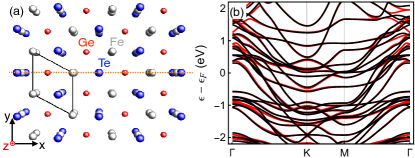
The atomic structure of a monolayer FGT is illustrated in Fig.1(a), where a top view is presented with some graphic perspective to show the vertical alignment of the atoms. The spectrum of the material is obtained from first-principles calculations within the framework of density functional theory (DFT) using the projector augmented wave pseudopotential [21, 22] as implemented in Vienna Ab initio Simulation Package (VASP) [23, 24]. The local density approximation [25] was used for the exchange-correlation energy. A energy cutoff for the plane-wave expansion was used throughout the calculations. The -centered mesh of in the two-dimensional Brillouin zone (BZ) was adopted. was chosen as the in-plane lattice constant for hexagonal lattice. After we obtained the eigenstates and eigenvalues, a unitary transformation of Bloch waves was performed to construct the tight-binding Hamiltonian in a Wannier function basis by using the maximally localized Wannier functions (WF) method [26] implemented in the Wannier90 package [27]. The WF-based Hamiltonian has the same eigenvalues as those obtained by first-principles calculations within of the Fermi level. The band structure of the tight-binding model is shown in Fig. 1(b). Here, the red solid curves represent the case where the magnetization is along , whereas the dark solid ones correspond to the out-of-plane magnetization along . The presence of SOC is evidently captured.
To examine the impact of the magnetization for low-temperature transport, we show the Fermi surfaces for both polarization cases in Figs. 1(c-d). When the magnetization is along [Fig. 1(c)], the Fermi surface possesses most symmetries of the non-magnetic crystal structure, including an apparent rotation. Note that the atomic structure also possesses reflection symmetry with respect to the x-z plane (), denoted by the orange dotted line in Fig. 1(a), and the mirror plane containing the Ge atoms (). When considering the magnetization along , the rotation and the reflection remain symmetric, whereas is broken by the spin. The irreducible wedge of the 1st Brillouin zone is therefore an equilateral triangle as shown in Fig. 1(c). The hexagonal full Brillouin zone can then be restored by rotations and another combination of reflection and time reversal (). On the other hand, when the magnetization is along , the spin breaks the symmetry, which is evident in the Fermi surface in Fig. 1(d). In this case, only and remain symmetric. The irreducible wedge of the Brillouin zone now becomes a rectangle [blue in Fig. 1(d)]. The path used in Fig. 1(b) is thus no longer a unique high-symmetry path, as shown in Fig. 1(d).
The change in the symmetry of the Fermi surface has a profound impact on the cryogenic magnetotransport property. At the limit of linear response governed by the Boltzmann transport equation, the transport of charge and spin is driven by the asymmetric part of the distribution function, , where is the electron charge, is the equilibrium distribution, is group velocity, and is the dependent relaxation time. At zero temperature, the Hall and the longitudinal conductivities can be obtained by collecting the Fermi-surface contributions from all bands, , where . Here, and represent the group-velocity components that are parallel and perpendicular to , respectively. Within the first Brillouin zone, one can parameterize the Fermi surfaces using the azimuthal angle of , such that , where is the angle between and , and . In the case of out-of-plane magnetization, if all scattering mechanisms preserve the crystalline symmetry, should also have rotation symmetry. Further using , we have
| (1) |
where Hall effects are strictly forbidden due to the zero integrand. Note that the band index is omitted in Eq. 1, suggesting that Hall effects given by such Fermi surfaces are forbidden for each individual band. However, when the magnetization is along , the symmetry of the Fermi surface is broken due to the strong SOC. As a result the integrand in Eq. 1 becomes finite, allowing for electric or spin Hall effects. We note that although FGT thin films are known to have a perpendicular easy axis, an in-plane saturation is experimentally feasible in a 4-layer thin film by applying an in-plane field of [5, 6].
To mimic the scenario where a monolayer FGT is weakly coupled to a spin system, we consider the scattering from a local spin:
| (2) |
where is a classical unit vector setting the polarization, denotes Pauli matrices of the itinerant spin, is the Hund’s-rule exchange coupling, and is the area of the localized impurity. At the leading-order approximation, the transition rate from to is given by Fermi’s golden rule where represents the periodic part of the wave function at , and is the number of impurity centers. Here, we consider and as two independent types of scattering mechanisms. When , the spin of the impurity is parallel to the magnetization. The Bloch states therefore diagonalize the scattering Hamiltonian, allowing only spin-preserved scattering: . However, when or along any other direction within the plane, spin-preserving scattering is forbidden: , allowing spin-flipping scatterings only.
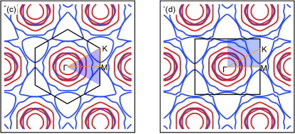
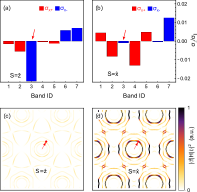
The selection rules strongly impact the transport property of monolayer FGT. This is a consequence of the spin composition and the density of states (DOS) on the Fermi surface. When the magnetization is along , four van Hove singularities [dark in Fig. 2(a)] are brought to the Fermi surface, resulting in large DOS for . However, these singularities vanish in the case of out-of-plane magnetization, where the two Fermi loops enclosing and are no longer intersecting [Fig. 2(b)]. The impact of these singularities becomes apparent considering the spin selection rule. When the impurity spins are along , the selection rule only allows the scattering of . Due to the large DOS of , the scattering rate of is dominating. In this case, has a much longer relaxation time, and therefore dominates the transport. On the other hand, when the impurities are polarized along , the selection rule now allows only . The large density of states for therefore makes the scattering of much more frequent. The relaxation time for now becomes greater, thereby dominating the transport and the Hall effects. Such transition of scattering rate can be seen from Figs. 2(c-d), where we illustrate the scattering rate from a chosen initial state (arrow, with the spin of ) to all possible final states on the Fermi surface. When , due to the spin selection rule, the initial positive spin is only allowed to scatter to negative spins hosting the van Hove singularities. This can be seen by the dark colors in Fig. 2(c). In contrast, when the scattering centers are polarized along , the originally dominating scattering is now forbidden, allowing only same-spin scattering, as shown in Fig. 2(d). Note that the spinless part of the Bloch states also affect the scattering rate, resulting in the variation of transition rates even within the same spin.
To quantitatively understand the transport signature of the spin-dependent scattering centers, we evaluate the full-band collision integral. Within the semi-classical approximation, the nonequilibrium distribution function satisfies . Considering detailed balance, the collision integral is given by , where is the scattering rate from to . Using the leading-order approximation, we have . Beyond the constant relaxation time approximation (RTA), should be dependent, satisfying , where is the group velocity of the eigenstate at . With some algebra, we have where . Further define the free-flight displacement along the field , the full-band Boltzmann equation reduces to a linear system:
| (3) |
where and are the normalized scattering matrix and the vector of free-flight displacements, respectively. Here, and . Note that the linear system defined by Eq. 3 is general for arbitrary combinations of scattering mechanisms included in . Although in principle the matrices are of uncountably infinite dimension, we will always deal with finite ones due to discretization in practice. The choice of discretization grid should be carefully made to avoid artificially breaking the symmetries that the system intrinsically hosts. In this practice, an equilateral triangular mesh is used to sample the irreducible wedge of the Brillouin zone. To demonstrate the result, we rotate away from by , and the free-flight displacement is plotted for and in Figs. 2(e) and (f), where the corresponding spin distribution is illustrated in Fig. 1(d). As discussed before, the values of for negative-spin bands are dominating when , as shown in Fig. 2(e). However, the for become much greater when , as shown in Fig. 2(f).
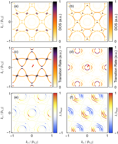
Once are obtained using Eq. 3, we calculate the Hall angle using , which depends only on the properties of scattering mechanisms and the geometry of the Fermi surface[28]. Here we illustrate the Hall angles given by the full-band Boltzmann equation at different directions of the field [Fig. 3(a)] and compare them to the RTA result (dark curve) where the details of the scattering mechanisms are neglected. Clearly, the sign of the Hall angle changes for different scattering mechanisms. To understand this trend, we compare the contributions given by different spins. For RTA, the bands with positive and negative spins almost have the same Hall angle as shown in Fig. 3(b). These two angles sum to the dark curve in Fig. 3(a), suggesting a net finite extrinsic anomalous Hall effect of the electric current. The spin Hall angle can then be obtained by subtracting the two spin contributions, resulting a near-zero spin Hall angle as shown by the orange curve in Fig. 3(b). The finite Hall effects captured here are a consequence of the FGT monolayer magnetization along , breaking the rotation symmetry. Consistent with the discussion shown in Eq. 1, when the magnetization is brought to , the symmetry is restored and the Hall effects are strictly forbidden, as numerically captured in Figs. 3(c-d).
Beyond RTA, the scenarios of Hall effects dramatically change once the scattering mechanisms are turned on. When the impurity spins are polarized along whereas keeping the magnetization along , the Hall angles for both positive and negative spins change sign, resulting in a net negative Hall angle when sweeps within as shown in Fig. 3(e). This suggests the important role of the scattering details. More interestingly, when the scattering centers are rotated to , only the Hall angle for negative spins changes sign, resulting in a finite net spin Hall effect as shown by the orange curve in Fig. 3(f). In this case, the net Hall effect of the electric current vanishes, which is consistent with the light-blue line in Fig. 3(a).
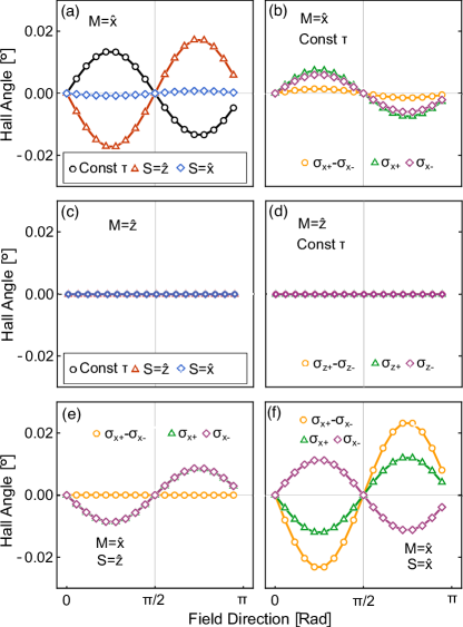
The transition between electric and spin Hall currents shown in Figs. 3(e-f) is not a consequence of symmetry. Instead, it is determined by the details of the Fermi surface and the scattering mechanism. Particularly, the transition is induced by the sign change of Hall angles for the negative-spin bands denoted by the purple curves in Figs. 3(e-f). To understand this, contributions to are resolved by the band indices and the spins, as illustrated in Figs. 4(a-b). Here the angle of the electric field is kept at from the magnetization. When , the 3rd band (dark red arrow, counting from ) on the Fermi surface contributes a large, negative Hall angle. Such contribution is given by a band of , resulting in a net negative Hall angle for negative spins. On the other hand, when , the contribution from the 3rd band almost vanishes [Fig. 4(b)]. This can also be seen from the scattering matrix elements with a chosen initial state in the 3rd band, as shown in Figs. 4(c-d). When , the 3rd band is forbidden to scatter into the van Hove singularities [Fig. 4(c)]. On the other hand, such scattering is allowed when , resulting in a small contribution to the transport and the Hall angle. The overall outcome is therefore a net positive Hall angle for negative spins, as shown by the purple curve in Fig. 3(f) at . Such positive spin Hall angle almost exactly cancels the negative Hall angle given by positive spins [green in Fig. 3(f)], such that the net Hall angle for the electric charge becomes vanishingly small. However, the magnitude of the spin Hall angle is maximized [orange in Fig. 3(f)], representing a pure spin current along the transverse direction.
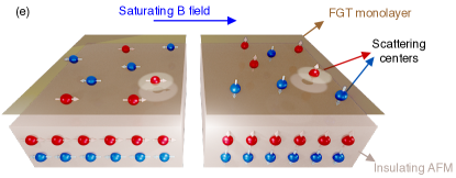
The transition between the electric and spin Hall effects in a monolayer FGT is a plausible way to detect the switching of an adjacent insulating magnetic material using carrier transport. This is particularly useful to detect the switching of an antiferromagnet (AFM) since the scattering selection rule is only sensitive to the orientation of the spins of the disorder, instead of the sign. Without electrons near the Fermi surface, insulating AFMs are expected to have small damping for the Néel-vector dynamics, allowing for switchings even faster than metallic ones. However, such switching is difficult to detect, which often involves optical imaging, spin-wave detection, or other non-trivial instrumentation. In a heterostructure illustrated in Fig. 4(e), the FGT monolayer is weakly coupled to an insulating AFM, such that the transport in the FGT layer experiences the sparse impurities with opposite spins provided by the AFM layer. The scattering selection rule survives the sign change of the disorder spins and is therefore robust against the surface roughness. Although the heterostructure illustrated in Fig. 4(e) suggests a layered AFM structure, collinear AFMs with other spin structures can also be detected via this mechanism. This may provide a convenient playground to investigate the spintronics of insulating antiferromagnets in general.
Acknowledgements.
Acknowledgments: This paper is based upon work supported by the National Science Foundation (US) under Grant No. ECCS-2151809. This work used Bridges-2 at Pittsburgh Supercomputing Center through allocation PHY230018 from the Advanced Cyberinfrastructure Coordination Ecosystem: Services & Support (ACCESS) program, which is supported by National Science Foundation (US) grants #2138259, #2138286, #2138307, #2137603, and #2138296.References
- Deiseroth et al. [2006] H.-J. Deiseroth, K. Aleksandrov, C. Reiner, L. Kienle, and R. K. Kremer, European Journal of Inorganic Chemistry 2006, 1561 (2006).
- Chen et al. [2013] B. Chen, J. Yang, H. Wang, M. Imai, H. Ohta, C. Michioka, K. Yoshimura, and M. Fang, J. Phys. Soc. Jpn. 82, 124711 (2013).
- Zhuang et al. [2016] H. L. Zhuang, P. R. C. Kent, and R. G. Hennig, Phys. Rev. B 93, 134407 (2016).
- Fei et al. [2018] Z. Fei, B. Huang, P. Malinowski, W. Wang, T. Song, J. Sanchez, W. Yao, D. Xiao, X. Zhu, A. F. May, et al., Nature Mater 17, 778 (2018).
- Deng et al. [2018] Y. Deng, Y. Yu, Y. Song, J. Zhang, N. Z. Wang, Z. Sun, Y. Yi, Y. Z. Wu, S. Wu, J. Zhu, et al., Nature 563, 94 (2018).
- Tan et al. [2018] C. Tan, J. Lee, S.-G. Jung, T. Park, S. Albarakati, J. Partridge, M. R. Field, D. G. McCulloch, L. Wang, and C. Lee, Nat Commun 9, 1554 (2018).
- May et al. [2019] A. F. May, D. Ovchinnikov, Q. Zheng, R. Hermann, S. Calder, B. Huang, Z. Fei, Y. Liu, X. Xu, and M. A. McGuire, ACS Nano 13, 4436 (2019).
- Gong et al. [2017] C. Gong, L. Li, Z. Li, H. Ji, A. Stern, Y. Xia, T. Cao, W. Bao, C. Wang, Y. Wang, et al., Nature 546, 265 (2017).
- Huang et al. [2018] B. Huang, G. Clark, D. R. Klein, D. MacNeill, E. Navarro-Moratalla, K. L. Seyler, N. Wilson, M. A. McGuire, D. H. Cobden, D. Xiao, et al., Nature Nanotech 13, 544 (2018).
- Ribeiro et al. [2022] M. Ribeiro, G. Gentile, A. Marty, D. Dosenovic, H. Okuno, C. Vergnaud, J.-F. Jacquot, D. Jalabert, D. Longo, P. Ohresser, et al., npj 2D Mater Appl 6, 1 (2022).
- Zhu et al. [2016] J.-X. Zhu, M. Janoschek, D. S. Chaves, J. C. Cezar, T. Durakiewicz, F. Ronning, Y. Sassa, M. Mansson, B. L. Scott, N. Wakeham, et al., Phys. Rev. B 93, 144404 (2016).
- Yi et al. [2016] J. Yi, H. Zhuang, Q. Zou, Z. Wu, G. Cao, S. Tang, S. A. Calder, P. R. C. Kent, D. Mandrus, and Z. Gai, 2D Mater. 4, 011005 (2016).
- Kim et al. [2018] K. Kim, J. Seo, E. Lee, K.-T. Ko, B. S. Kim, B. G. Jang, J. M. Ok, J. Lee, Y. J. Jo, W. Kang, et al., Nature Mater 17, 794 (2018).
- Gong and Zhang [2019] C. Gong and X. Zhang, Science 363, eaav4450 (2019).
- Gibertini et al. [2019] M. Gibertini, M. Koperski, A. F. Morpurgo, and K. S. Novoselov, Nat. Nanotechnol. 14, 408 (2019).
- Wang et al. [2018] Z. Wang, D. Sapkota, T. Taniguchi, K. Watanabe, D. Mandrus, and A. F. Morpurgo, Nano Lett. 18, 4303 (2018).
- Wu et al. [2020] Y. Wu, S. Zhang, J. Zhang, W. Wang, Y. L. Zhu, J. Hu, G. Yin, K. Wong, C. Fang, C. Wan, et al., Nat Commun 11, 3860 (2020).
- Wang et al. [2019] X. Wang, J. Tang, X. Xia, C. He, J. Zhang, Y. Liu, C. Wan, C. Fang, C. Guo, W. Yang, et al., Science Advances 5, eaaw8904 (2019).
- Huang et al. [2020] B. Huang, M. A. McGuire, A. F. May, D. Xiao, P. Jarillo-Herrero, and X. Xu, Nat. Mater. 19, 1276 (2020).
- Lin and Ni [2019] X. Lin and J. Ni, Phys. Rev. B 100, 085403 (2019).
- Blöchl [1994] P. E. Blöchl, Phys. Rev. B 50, 17953 (1994).
- Kresse and Joubert [1999] G. Kresse and D. Joubert, Phys. Rev. B 59, 1758 (1999).
- Kresse and Furthmüller [1996a] G. Kresse and J. Furthmüller, Computational Materials Science 6, 15 (1996a).
- Kresse and Furthmüller [1996b] G. Kresse and J. Furthmüller, Phys. Rev. B 54, 11169 (1996b).
- Perdew and Zunger [1981] J. P. Perdew and A. Zunger, Phys. Rev. B 23, 5048 (1981).
- Marzari et al. [2012] N. Marzari, A. A. Mostofi, J. R. Yates, I. Souza, and D. Vanderbilt, Rev. Mod. Phys. 84, 1419 (2012).
- Mostofi et al. [2014] A. A. Mostofi, J. R. Yates, G. Pizzi, Y.-S. Lee, I. Souza, D. Vanderbilt, and N. Marzari, Computer Physics Communications 185, 2309 (2014).
- Ong [1991] N. P. Ong, Phys. Rev. B 43, 193 (1991).