Broadband composite nonreciprocal polarization wave plates and optical isolators
Abstract
We provide a technique for a broadband nonreciprocal wave retarder whose quarter-wave plate phase retardation is the same in forward and backward directions. The system is built using a number of sequential nonreciprocal wave plates. The proposed device can also be utilized to create a broadband optical diode, which consists of two achromatic quarter-wave plates, one reciprocal and the other non-reciprocal, that are sandwiched between two polarizers aligned in parallel.
I Introduction
For decades, reciprocal and broadband (achromatic) polarization retarders have been a topic of intense attention in optics Hecht ; Wolf ; Azzam ; Goldstein . Traditionally, two or more conventional wave plates, of the same or different materials, are combined to make such retarders. West and Makas West reported achromatic combinations of plates with various birefringence dispersions as one of the first known ideas. Destriau and Prouteau Destriau presented achromatic retarders made out of wave plates of the same material but different thicknesses for two birefringent plates, while Pancharatnam offered three plates for half-wave Pancharatnam1 and quarter-wave Pancharatnam2 retarders. Harris and colleagues later presented achromatic quarter-wave plates with six Harris1 and ten identical quarter-wave plates Harris2 . The analogy between the polarization Jones vector and the quantum state vector has recently been used to suggest arbitrarily precise broadband polarization retarders Ardavan ; Ivanov ; Peters .
All of the above achromatic wave plates are reciprocal, in the sense that their function is invariant upon time inversion. However, as recently shown by Al-Mahmoud et. al Mahmoud , wave plates retarders can be non-reciprocal whose phase-shift retardation depends on the light propagation direction. For example, a retarder with retardation of in the forward direction (quarter-wave plate) and in the backward direction (half-wave plate) or other combination of retardance values can be realized. The Al-Mahmoud et. al Mahmoud non-reciprocal elements are based on magneto-optical phenomena like the Faraday effect. The axial (as opposed to polar) structure of the magnetic field and magnetization vectors in this case, as well as the associated invariance upon space inversion, are what cause the non-reciprocity. In Al-Mahmoud et. al Mahmoud experiment, it was shown that a non-reciprocal Faraday rotator combined with a reciprocal rotator made of two half-wave plates sandwiched between crossed quarter-wave plates could be used to realize adjustable non-reciprocal wave retarders with retardation that differed in the forward and backward directions Mahmoud .
In this paper, we theoretically propose novel broadband polarization quarter-wave plates, which are also nonreciprocal, with the potential to be used in broadband optical isolators or/and circulators for telecommunications, industrial, and laboratory research.
II Background
The waveplate is a birefringent medium that modifies the polarization state by adding a phase shift of between the two orthogonal polarization components. The half-wave plate and quarter-wave plate retarders are the most popular waveplates, with phase shifts of and , respectively. The waveplate retarder’s Jones matrix, whose axes are aligned with the lab axes, takes the shape of a diagonal matrix,
| (1) |
where is the phase shift, is the wavelength in vacuum, and are the refractive indices along the fast and slow axes respectively, and is the thickness of the waveplate. When the waveplate retarder’s axes are rotated by an angle with regard to the lab axes, the Jones matrix is given by
| (2) |
with rotation matrix in the horizontal-vertical (HV) basis given by
| (3) |
Another way to realize a retarder is to use a polarization rotator at an angle sandwiched in between two quarter-wave plates rotated by angles and with respect to the lab reference frame correspondingly Messaadi . The Jones matrix for such a sequence can be given by the product of the Jones matrices of the quarter-wave plates and the rotator:
| (4) |
The last part of Eq. (4) demonstrates that the whole sequence can be considered an effective wave plate with an effective retardation . If one uses Faraday rotator (nonreciprocal device) then the effective waveplate is also nonreciprocal Mahmoud . Even though the two quarter-wave plates can be achromatic — an assumption we make from now on — the effective wave plate is not broadband due to the strong wavelength dependence on the Verdet constant. Our objective in the present paper is to construct broadband nonreciprocal wave plates using a sequence of several nonreciprocal retarders, each with a specific phase shift and rotated by specific angles.
III Composite wave plate
Now we will show three different sequences to construct nonreciprocal broadband quarter-wave plates.
-
•
The first approach is to combine two nonreciprocal quarter-wave plates and one nonreciprocal half-wave plate. This composition is described by the Jones matrix
(5) -
•
The second approach is to combine two nonreciprocal half-wave plates and one nonreciprocal quarter-wave plate, characterized by the Jones matrix
(6) -
•
The third approach is to have multiple nonreciprocal wave plates in the sequence, e.g., combining four nonreciprocal half-wave plates and one nonreciprocal quarter-wave plate. The Jones matrix of this structure reads
(7) Here and represent the systematic deviations from the nominal retardation of the half- and quarter-wave plates respectively.
We note that a combination of only reciprocal elements leads to reciprocal sequence, but the combination of reciprocal and nonreciprocal elements may lead to reciprocal or nonreciprocal sequences. For the above odd number of sequences (5)-(7) one can easily check that they are nonreciprocal.
The composite retarder’s efficiency is evaluated in terms of the fidelity Ardavan ,
| (8) |
where is the achieved and is the target Jones matrix. if the two operators and are identical, but the fidelity reduces if the two matrices differ. In order to produce broadband nonreciprocal quarter-wave plate we determine the rotation angles of each wave plate in Eqs. (5), (6) or (7) by using the Monte Carlo method. We generate 104 sets of random angles and . We select solutions, which deliver the biggest overall fidelity in the interval of and also, ensure a flat top. The angles are presented in table 1. It is important to note that the parameters given in table 1 are not the only possible. Obviously, for the wavelength at which the wave plates serve as half or quarter-wave plates, respectively, we have and .
IV Broadband optical isolator
Another interesting case is when the sequence serves as a broadband null retarder in one direction and a broadband half-wave plate in the other direction, which can be archived if we combine our nonreciprocal broadband quarter-wave plate with a commercially available broadband but reciprocal quarter-wave plate. In this case, one can build a broadband optical isolator as shown and explained in Fig. 1.
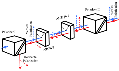
The working principle of the proposed optical isolator is the following. Any light beam entering through the polarizer I will exit vertically polarized (blue array), after passing through the achromatic reciprocal quarter-wave plate (ARQWP) the light will be circularly polarized, then passing through the achromatic nonreciprocal quarter-wave plate (ANRQWP) it will be again vertically polarized, thus all light will pass polarizer II. On the way back, if the light re-enters the polarizer II in the backward direction (red array), due to the combined effect of the ANRQWP and ARQWP, the polarization is rotated in such a way (90 degrees) that the whole wave is blocked by the polarizer I, so that no light can exit from right to left.
V Numerical calculations
We explained the basic concept of creating broadband nonreciprocal polarization quarter-wave plates and broadband optical isolators in the previous sections. Now, we present numerical simulations to test the effectiveness of the design we have discussed above.
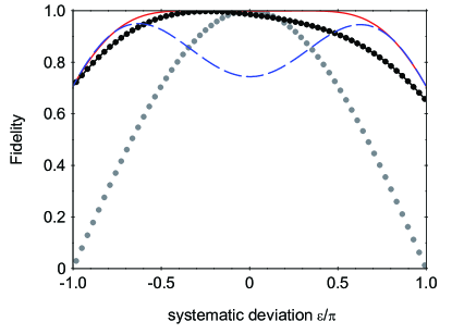
In Figure 2 we show the calculation for the fidelity profiles using the three configurations (5), (6) and (7) with rotation angles taken from table 1. Obviously, the configuration (7) outperforms the other configurations and this is expected because configuration (7) has five retarders in the series compared to three retarders in case of (5) and (6). In theory, the fidelity profiles can be made arbitrarily flat by increasing the number of retarders in the series. In practice, it is not clear whether such many-retarders sequences will be useful, due to the many optical elements in the series (Faraday rotators and quarter-wave plates), therefore we limit our investigation to five nonreciprocal quarter-wave plates (five Faraday rotators and ten quarter-wave plates altogether).
For broadband optical isolator simulations in this paper, we use terbium gallium garnet crystal (TGG) as it is one of the most common crystals for Faraday rotators. We fix the applied magnetic field to 1 T, the length of the crystal is considered to be 1 cm for the half-wave plates and 0.5 cm for the quarter-wave plates. Up until now, there has been a lot of research done on the dispersion of the TGG Verdet constant Bozinis1978 ; Jannin1998 ; Yoshida . It was demonstrated that the following formula can adequately represent the wavelength dependence of this crystal,
| (9) |
where and nm is the effective transition wavelength. TGG has optimal material properties for the Faraday rotator in the range of 400 – 1100 nm, excluding 470 – 500 nm (the absorption window). For most materials, the Verdet constant decreases (in absolute value) with increasing wavelength: for TGG it is equal to at nm and at nm. The operating wavelength range of the Faraday isolator is constrained as a result of this.
The performance of the optical isolators is quantified by its transmission (a portion of the input light’s intensity that passes through the isolator), back-transmission (a portion of the back-transmission light’s intensity that passes through the isolator in the opposite direction), and isolation . The light intensity measured after passing the optical diode in both the forward () and backward () directions determine these numbers, respectively,
| (10a) | |||||
| (10b) | |||||
| where stand for vertical polarizers, is the Jones vector for the light entering the isolator, and and are Jones matrices for forward and backward wave plates respectively. has the meaning of the intensity of light at the beginning of the Faraday isolator. The isolation is then determined with the formula Kim2006 ; Adams2012 | |||||
| (11) |
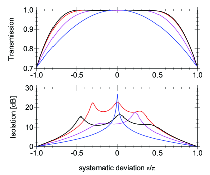
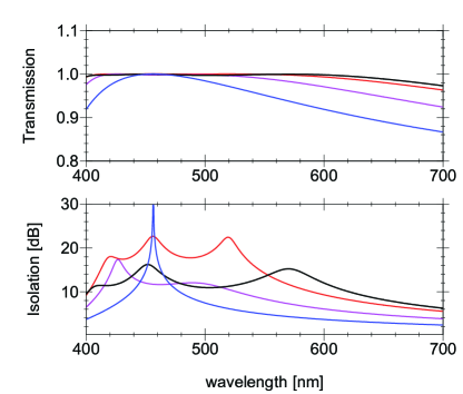
The transmission and isolation profiles for the three configurations (5), (6) and (7) are shown in Figs. 3 and 4. One can notice that for all these composite isolators both the transmission and isolation are far more efficient than that of isolators using a single rotator (blue curve). Figure 3 shows the performance of the optical isolators under study with respect to the systematic deviation of the Faraday rotators, whereas in Fig. 4 the analogous dependence on wavelength is presented. The long tail asymmetry seen in Fig. 4 stems from the fact that the Faraday rotation angle depends non-linearly on the wavelength (as seen in Eq. (9)). The isolation above 10 dB over a region of 200 nm can be seen from Fig. 4, and it is a much broader spectral range compared to the case of using just a single Faraday rotator (about 20 nm on the level of 10 dB).
We emphasize that the transmission and isolation curves were calculated under the assumption of no losses in realistic realizations. Insertion losses and reflections from the surfaces of the optical elements are the primary causes of the reduced transmission. Losses resulting from optical element propagation would not be as significant.
VI Conclusion
We have presented a novel way to construct broadband nonreciprocal polarization quarter-wave plates. The concept is based on combination of several nonreciprocal waveplates with the optical axis of each rotated by appropriate angles. In addition, the proposed broadband nonreciprocal polarization quarter-wave plate can be used in combination with a broadband reciprocal polarization quarter-wave plate to build a broadband optical isolator. The isolation bandwidth (isolation of more than 10 dB) is almost 200 nm while the transmission bandwidth is beyond 200 nm. This isolator has the benefit of being resistant to changes in temperature, crystal length, and magnetic field. With the available optical components, an experimental implementation should be feasible.
Acknowledgments
This research is partially supported by Bulgarian national plan for recovery and resilience, contract BG-RRP-2.004-0008-C01 SUMMIT: Sofia University Marking Momentum for Innovation and Technological Transfer, project number 3.1.4. and the University of Sofia Grant 80-10-26/20.04.2023.
References
- (1) M. Born and E. Wolf, Principles of Optics (Pergamon, 1975).
- (2) E. Hecht, Optics (4th Edition) (Addison Wesley, 2002).
- (3) D. Goldstein and E. Collett, Polarized Light (CRC, 2003).
- (4) M. A. Azzam and N. M. Bashara , Ellipsometry and Polarized Light (North Holland, Amsterdam, 1977).
- (5) C. D. West and A. S. Makas, J. Opt. Soc. Am. 39, 791–794 (1949).
- (6) M. G. Destriau and J. Prouteau, J. Phys. Radium 10, 53–55 (1949).
- (7) S. Pancharatnam, Proc. Indian Acad. Sci. A41, 130–136 (1955).
- (8) S. Pancharatnam, Proc. Indian Acad. Sci. A41, 137–144 (1955).
- (9) E. Harris, E. O. Ammann, and A. C. Chang, J. Opt. Soc. Am. 54, 1267–1279 (1964).
- (10) C. M. McIntyre and S. E. Harris, J. Opt. Soc. Am. 58, 1575–1580 (1968).
- (11) A. Ardavan, New J. Phys. 9, 24–24 (2007).
- (12) S. S. Ivanov, A. A. Rangelov, N. V. Vitanov, T. Peters, and T. Halfmann, J. Opt. Soc. Am. A 29, 265 (2012).
- (13) T. Peters, S.S. Ivanov, D. Englisch, A.A. Rangelov, N.V. Vitanov, T. Halfmann, Appl. Opt. 51, 7466 (2012).
- (14) M. Al-Mahmoud, H. Hristova, V. Coda, A. A. Rangelov, N. V. Vitanov, and G. Montemezzani, OSA Continuum Vol. 4, Issue 10, pp. 2695-2702 (2021).
- (15) A. Messaadi, M. M. Sanchez-Lopez, A. Vargas, P. Garcia-Martinez, and I. Moreno, Opt. Lett. 43, 3277–3280 (2018).
- (16) A. B. Villaverde, D. A. Donatti, D. G. Bozinis, J. Phys. C: Solid State Phys. 11, L495–L498 (1978).
- (17) X. Chen, B. Lavorel, J. P. Boquillon, R. Saint-Loup and M. Jannin, Solid State Electronics 42, 1765–1766 (1998).
- (18) H. Yoshida, K. Tsubakimoto, Y. Fujimoto, K. Mikami, H. Fujita, N. Miyanaga, H. Nozawa, H. Yagi, T. Yanigatani, Y. Nagata and H. Kinoshita, Opt. Express 19, 15181 – 15187 (2011).
- (19) Jin Seung Kim and Jun Keun Chang, J. Kor. Phys. Soc. 48, 51–55 (2006).
- (20) L. Weller, K. S. Kleinbach, M. A. Zentile, S. Knappe, I. G. Hughes and C. S. Adams, Opt. Lett. 37, 3405 – 3407 (2012).