neda.naseri@mtsu.edu
Mechanism of laser induced self-organized void array formation in Polydimethylsiloxane (PDMS)
Abstract
This study investigated the formation of multi-voids in polydimethylsiloxane (PDMS) using a multi-pulse irradiation method and explored the impact of laser energy, number of pulses per micron (writing speed), and laser spot size (NA) on the process. The experimental results revealed that multi-void formation occurred due to multi-pulse irradiation in the bulk of PDMS. Additionally, increasing laser energy led to an increase in the number of voids, while the number of voids did not change with an increase in the number of pulses per micron for a fixed laser parameter. However, the size of the voids increased with the number of pulses per micron, and tighter focusing conditions (higher NA) resulted in smaller voids with a shorter distance between them. Furthermore, Finite-Difference-Time-Domain (FDTD) simulations reproduced the generation of void arrays in PDMS using a similar multi-laser pulse approach. By modeling the voids as concentric spheres with densified shells and simulating the laser interaction with the voids, we showed that void array generation in PDMS is a linear mechanism. This study provides valuable insight into the mechanism behind the formation of void arrays in PDMS. The simulation results agrees well with the experimental results to further validate the model and gain a better understanding of the physical processes involved in the generation of void arrays in PDMS.
I introduction
Femtosecond laser modification and damage to transparent materials has been an active research area for decades due to numerous promising applications in different areas of photonics Gattas ; Zhang2016 ; Beresna2017 ; Drev . Interaction of femtosecond laser pulses with transparent materials and polymers can lead to various processes depending on laser intensity and laser spot size. Among these modifications, void formation induced by femtosecond laser pulses has received significant attention due to its potential applications in devices such as optical memories, waveguides, gratings, couplers, and chemical and biological membranesGraf ; Beresna ; Bell ; Davis ; Shimotsuma ; Zhang ; Zhang2016 ; Beresna2017 ; Drev . The fabrication of voids in silica glass Glezer1996 ; Glezer1997 ; Watanabe1999 ; Watanabe2000 ; Toratani2005 ; Dai2016 and polymers Yamasaki2000 ; Day2002 has been widely reported in numerous studies since Glezer et al. Glezer1996 pioneering work. The shape of the damage structure in transparent materials and polymers is determined by the laser focusing condition. Numerical and experimental studies conducted over the past two decades on single-pulse filamentation in transparent materials have demonstrated that the femtosecond laser interaction with the material is heavily influenced by the laser focusing conditions. Tight focusing produces voids Glezer1997 ; Schaffer2001 , while loose focusing creates long channels of modified refractive index (See. Naseri, et. al Naseri and references there). Loose laser focusing condition refers to laser spot size of a few times larger than the laser wavelength. In this regime, the dominant process is the nonlinear Kerr effect, which leads to the formation of filaments as the laser pulse interacts with the material. In contrast, the tight focusing condition is characterized by laser spot sizes comparable to or smaller than the laser wavelength, with optical focusing as the dominant mechanism. This results in the formation of a void structure near the geometrical focus position Naseri . The number of laser pulses that interact with the material also plays a significant role in determining the outcome of the laser-material interaction.
A void structure is characterized by a central volume of less dense material that is surrounded by a higher density material, as reported by Glezer et al. in their 1996 and 1997 studies Glezer1996 ; Glezer1997 . Despite extensive research dedicated to elucidating the mechanisms behind multi-void formation in materials, the underlying aspects and mechanism of self-void array formation in dielectrics and polymers remain poorly understood.
Previous studies have suggested that self-focusing Kanehira and spherical aberration Song ; Wang are mechanisms responsible for laser-induced multi-void formation. However, the laser re-focusing period Wu is much longer than that of the void arrays, and it only occurs under loose laser focusing conditions, which is not the case for multi-void formation. As a result, nonlinear self-focusing is unlikely to be the mechanism responsible for the formation of void arrays. Gaining a better understanding of the mechanisms underlying void array formation in materials could enable higher precision micromachining and more precise control over induced material changes.
In this paper, we experimentally show that multi-void formation is primarily due to irradiation of a dielectric medium by multiple laser pulses under tight focusing conditions. We investigate the effects of laser pulse energy, number of laser pulses, and laser spot size on the size and number of voids in a string/array generated in Polydimethylsiloxane (PDMS). The size of the voids decrease with the progress of the pulses inside the medium. Numerically, we show that when a dielectric medium is irradiated by multiple laser pulses, the first pulses causes a localized refractive index modification inside the medium that acts as a focusing lens by which the subsequent pulses are focused. Once the subsequent pulses are focused by the new medium, it creates a second modification in the refractive index. The size of the first void (curvature) affect the size of the second void as well as the distance between the first and the second voids. This process is reinforced by multiple laser pulses eventually creating a string/array of voids. Our model eliminates the effects of spherical aberrations and confirms that multi-void formation is a multi-pulse effect, and is mostly a linear mechanism.
II experimental setup
Femtosecond pulses from a Ti:Sapphire regenerative amplifier, operating at a repetition rate of 1 kHz, 800 nm, and 40 fs with maximum output energy of 2.5 , were focused 300 below the surface of PDMS by 0.50 and 0.65 numerical aperture aspheric microscope objectives. Polydimethylsiloxane (PDMS) sample was placed on three-axis translation stages with a resolution of 50 nm along the lateral dimensions (X,Y) and 100 nm along the axial direction (Z). PDMS is an optically transparent and inert material, widely used in photonic applications owing to its excellent chemical stability and moldability, and being inexpensive.
The position of the laser focus relative to the surface of bulk PDMS sample was precisely determined by imaging the back-reflected light with a CCD camera at low pulse energies, below the ablation threshold. By translating the PDMS at different speeds the number of laser pulses incident per micron of the sample was varied. A combination of a half-wave plate and polarizer were used to vary the pulse energy. The incident pulse energies were measured after the microscope objective and monitored by a calibrated fast photodiode operating in linear regime. The pulse duration was measured to be 65 at the back aperture of the objective after passing through all the optics by means of a single-shot autocorrelations.
PDMS samples were prepared by mixing Dow Corning Sylgard 184 silicone elastomer base with curing agent in 10:1 ratio. The mixture was stirred for 10 minutes and degassed by placing it in a vacuum desiccator for 30 minutes. The mixture was then poured between four glasses slides that were attached to a silicon wafer that was cleaned by methanol. Another glass slide was used to gently spread the PDMS mixture avoiding any air bubbles. A weight of 500 g was positioned on the top of the glass slide to ensure flat top and the bottom surfaces. The mixture was cured in the oven at 80◦C for two hours. Large sheets with dimensions of were prepared that were subsequently cut into smaller samples of . After laser modification of PDMS the samples were cleaved and gold coated for characterization with scanning electron microscope (SEM).
III Experimental Results
To investigate laser induced modification of PDMS, lines were fabricated with different pulse energies, speeds and laser spot sizes. The samples were then cut into two pieces perpendicular to the scan direction of the laser beam. The inside surfaces were characterized by Scanning Electron Microscope(SEM) as shown in figures 1,2. We first investigate the effect of laser pulse energy. Figure 1a shows SEM images of the single and multi-void formation for varying laser pulse energy when femtosecond pulses were focused by a 0.5 NA objective and a fixed writing speed of 0.1mm/s corresponding to an irradiation by 10 laser pulses per micron. When the pulse energy is close to the threshold energy, a single void was formed. Increasing the pulse energy lead to formation of quasi periodic-self-formed voids. In addition, void size (ones closer to the surface where light was incident) and their spacing increased with pulse energy.
Irradiation of PDMS with a single femtosecond pulse of different energies produced a single void. Figures 4, 5 reveal that the multi-void structure is a consequence of irradiating PDMS with multiple laser pulses irradiation. For a fixed pulse energy, increasing the number of laser pulses (Fig. 1 b) marginally increased the number of voids. However, the size of the voids increases with the number of pulses per micron. The SEM images also reveals that the position of the first void is back shifted with the increase of peak power of the laser pulse and number of pulses per micron as shown in figure 1 (a,b). Figure 2 shows that beside the number of laser pulses and pulse energy, the numerical aperture of the microscope objective (laser spot size) also affects the number of voids per a single array. Focusing femtosecond pulses with a 0.68 NA objective resulted in 7-10 voids per single array in contrast to a maximum of four voids formed with 0.5 NA objective. In addition, the back shifting of the first void is not as dramatic as with 0.5NA objective. Also, the void sizes and the distance between them are smaller. Unlike the results of 0.5 NA objective, the number of laser pulses appear to have more significant influence on multi-void formation.
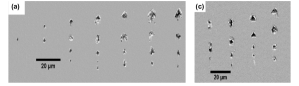
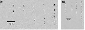
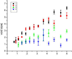
Figure 3 compares the size of the voids of different orders with increasing the laser pulse energy. The first order void is the one closest to the surface on which light is incident. For certain laser peak power, the size of the voids decreases with their order; first generated void is the largest, while fourth void is the smallest. Figure 3 also shows that for each void order, increasing the laser peak power results in larger void sizes. For example, the first generated void is the largest for the highest laser peak power, and this behavior holds for the second, third and fourth generated voids.
.
IV Numerical method
To understand the mechanism of multi-void formation and our experimental results, we performed three-dimensional high resolution finite-difference-time-domain (FDTD) simulations. To-date, such simulations relied on nonlinear pulse propagation with plasma generation and dynamics, using approximations such as slowly varying envelopes or evolving waves, to obtain an evolution equation for the pulse Cou . This method has proven to be effective when the right approximations are made for the specific problem, such as in cases where the focusing is not too tight, the medium is relatively uniform, and the plasma created is not too dense Dub . However, since the spot size of the laser and the void size in materials are usually a fraction of the laser wavelength, a more rigorous computational approach that does not make any assumptions about light propagation is required Popov2011 ; Bulga ; Rudenko .
First we study the interaction of a single laser pulse with PDMS. Our numerical modeling show that increasing the laser energy in single pulse interaction results in elongated single void formation and not a void array. Then we model the first damage structure (void) as pre-recorded into the medium and study the interaction of the laser pulse with the void. We show the generation of the second void as a result of field enhancement in front of the first void. As a next step, we model the two generated voids as pre-recorded in the medium and show the third void generation. Our method shows that this can continue, and successive void can be generated as a result of multi-laser interaction in PDMS.
In our 3D numerical simulation model, Maxwell’s equations are solved using the FDTD method Taflove2005 via Yee algorithm Yee ; Popov with constitutive relations (cgs units), and current density . E and B are the electromagnetic fields, D the displacement vector, H, the magnetic field auxiliary vector, is the linear susceptibility of the material, and is the Kerr susceptibility, which we take to be constant. The electromagnetic response of the generated plasma is represented by and laser depletion due to photo ionization (PI) by . The evolution of the free electron density, , is described as: , where is the PI rate. We use Keldysh’s formulation for the PI rate Keldysh . Following Keldysh’s Formulation Keldysh , the adiabaticity parameter for solids , where denotes the reduced mass of the electron and the hole, is band gap energy, is the laser electric field, and is the laser frequency. While we have implemented a model of avalanche ionization that follows Ref. Rethfeld , we find that our simulation results for pulses including avalanche ionization were identical to equivalent simulations that did not include avalanche ionization. Thus, to save computational resources, we did not enable avalanche ionization in our code for the simulations presented here. We assume a laser beam focused by a perfectly reflecting parabolic mirror characterized by a given , corresponding to laser beam waist sizes of . Our model thereby eliminates the effects of spherical aberrations. The laser incident onto the mirror is a Gaussian beam whose beam waist is half the size of the mirror. To describe the fields focused by the parabolic mirror, the Stratton-Chu integralsPopov2009 ; Stratun are used, which specify the exact electromagnetic field emitted by the given parabolic surface. This field is calculated on five boundaries of the 3D FDTD simulation in a total field/scattered field framework. The laser pulses are Gaussian in time with a pulse duration of and a wavelength of and they are linearly polarized along the y direction and propagating along the x direction. The geometrical laser focus is located at , and the simulation domain is , with grid size . To ensure the domain was large enough, we chose it such that, in all simulations, the laser pulse was no longer creating plasma well before it exited the domain. Further, we ran simulations where we placed the geometric focus much deeper within the simulation domain and found no difference in our results.
Linear refractive index of PDMS is .
The saturation density is estimated for PDMS as , where is the critical electron density for the free-space laser wavelength . The saturation density is the maximum density that can be reached when every molecule is ionized.
The FDTD simulates linear and nonlinear laser propagation in the medium, plasma generation, ionizational and collisional energy losses as well as laser interaction with the plasma free particles. The accuracy of the simulations is limited by the uncertainties in some of the parameters involved. The third- order susceptibility, , of pure PMMA is relatively well known and is estimated to be Damore2004 . The polymer used in the experiment is PDMS. of PDMS is not well known. Here we used the of PMMA, however we show that the physical process is linear, therefore not really dependent on nonlinear susceptibility of the material. We present the results of our simulations with twice of PMMA and with Kerr effect turned off and show that the interaction is linear, therefore the overall results won’t change with varying the nonlinear susceptibility of the material.
V Simulation results and discussion
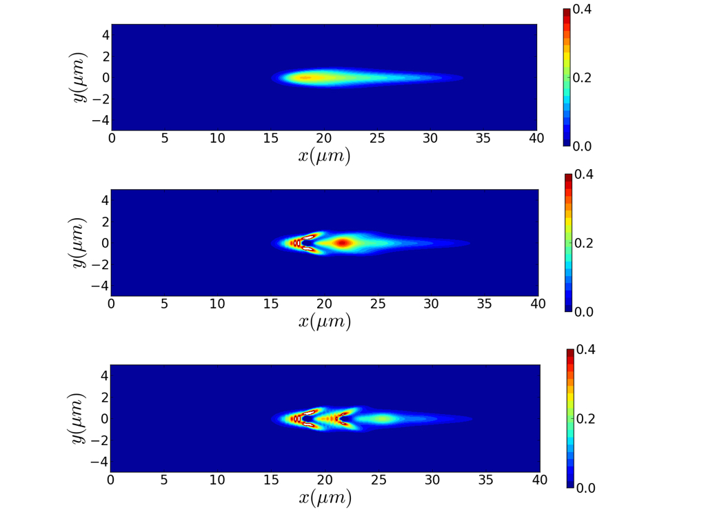
The mechanism of void array formation, as observed in the experiments is a multi-laser pulse effect. The first pulse generates a single void structure, and subsequent irradiation leads to the formation of multiple voids (see Figure 4). In order to understand the mechanism of multi-void formation, first we performed simulations of laser interaction with bulk PDMS. The resulting electron density structure, depicted in Figure 4-a, closely resembles the experimental findings, featuring an oval-shaped void located at with a maximum electron density of . Notably, the damage threshold density for PDMS is lower than that of fused silica, and we set the cut-off damage threshold density for PDMS at .The simulation also indicates that the laser focus position in PDMS is near the geometrical focus, suggesting that Kerr nonlinearity is not the primary interaction mechanism. The plasma is confined to near the geometric focus, and is rapidly formed.
Plasma defocusing is also seen, but since geometric defocusing is so strong (after the geometrical
focus), it dominates over Kerr self-focusing.
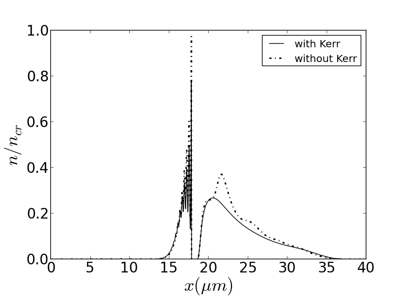
To investigate the role of Kerr self-focusing, we conducted simulations similar to the previous simulation (Figure 4-a), but with the nonlinear Kerr effect disabled by setting the Kerr susceptibility to zero. The results, shown in Figures 5 and 6-a, confirm that Kerr nonlinearity is not the dominant mechanism, and that geometric focusing plays a more significant role. Figure 5 displays the plasma density along the laser axis after the laser pulse exits the medium, with the solid and dash-dotted curves representing the results obtained with and without the Kerr effect, respectively. Figure 6-a presents the corresponding contour plot.
To further confirm that the interaction is linear, we conducted additional simulations equivalent to Figure 4-a, except that we doubled the Kerr nonlinear susceptibility (). The resulting plasma density along the laser axis is displayed in Figure 5. The solid, dashed, and dotted-dashed lines represent the simulations with Kerr nonlinearity included, turned off, and with doubled nonlinear susceptibility, respectively. As seen in Figure 5, the location of the void is not significantly affected in any of the three simulations, and the plasma density is well above the damage threshold. The maximum plasma density values, , obtained with and without Kerr effect, as well as with twice the nonlinear coefficient , are all close to each other and above the permanent damage threshold. We therefore conclude that the Kerr nonlinear effect does not play a dominant role, and that geometric focusing is the primary mechanism. It is worth noting that increasing the intensity of the laser pulse was expected to generate multiple voids, but our simulations revealed that it results in an elongated void, confirming the experimental findings.

We have developed a novel model to better understand the mechanism behind the formation of multiple voids observed in the experiments. The model consists of a concentric sphere with an inner radius of m and an outer radius of m. The center of the sphere was filled with air to simulate the refractive index of the void, while the shell had a slightly higher linear refractive index than PDMS to model the densified shell (). The location of the modeled void was determined based on the location where the maximum plasma density was observed in the previous simulation with the Kerr effect included m) (Fig. 4). All other parameters were kept the same as in the previous simulation.
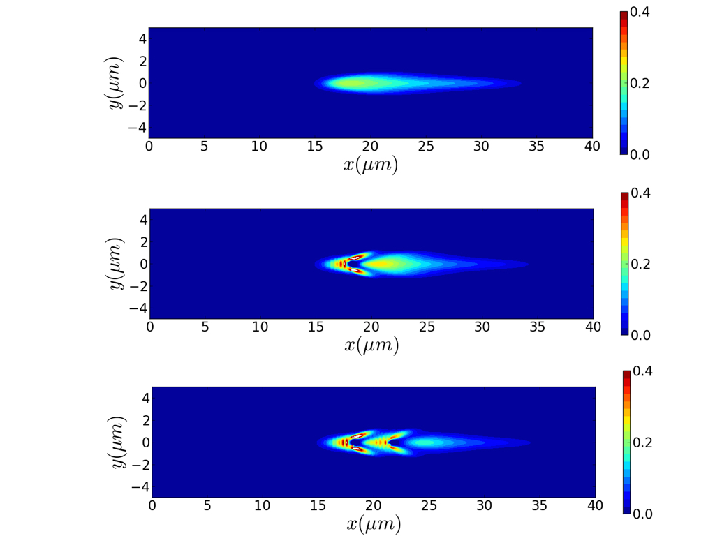
The laser pulse, which could be the second or third pulse in the experiment, enters the medium from the left boundary and interacts with the medium containing a pre-recorded void. The electric field enhancement occurs on the right side of the pre-recorded void, leading to the formation of a second void. The plasma density contour plot after the laser pulse has left the medium is shown in Figure 4-b. A portion of the laser pulse scatters from the void and focuses in front of it, at a distance of m from the center of the void, where the laser intensity is sufficient to ionize the PDMS medium, resulting in the formation of a second void at a distance of m with a radius of m. To verify that this mechanism is linear, we performed simulations similar to those in Figure 4-b but with the nonlinear Kerr effect turned off by setting the Kerr susceptibility to zero. The resulting plasma densities along the laser axis are shown in Fig. 8. The position of the laser focus in front of the void is almost identical to that in the simulation with the nonlinear Kerr effect included, and the maximum electron density is also similar. Therefore, we conclude that the interaction of the second (or third) laser pulse with PDMS is a linear effect, and the leading mechanism is geometrical focusing.
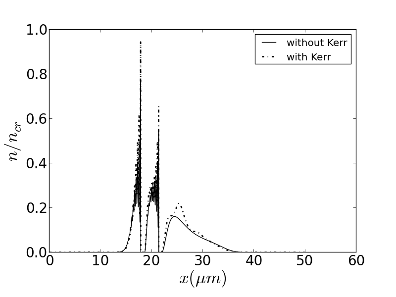
To verify that the void generation continued with pre-recorded voids, we modeled the first and the second voids as concentric spheres with refractive index of air in the centers, and densified shells with slightly higher linear refractive index than the medium (). The modeled voids were placed at the locations where the first and the second void were observed (Fig.4). Figure 4-c illustrates the interaction of the laser with two voids previously recorded. The contour plot of the electron density shows the generation of the third void in front of the second void, where field enhancement occurred in the right side of the second void. The radius of the third void was , and the electron density was above the damage threshold. The process of void array generation in PDMS can continue by adding the voids one after another using the method presented here.
The mechanism presented in this study clearly illustrates the successive generation of voids in PDMS as a result of multi-laser pulse interaction. To confirm that nonlinearity is not the leading process in void generation, we conducted simulations with one and two voids while turning off the Kerr nonlinearity and keeping other parameters the same as in Fig. 4-c. The electron density contour plots with nonlinear Kerr effect turned off are shown in Figs. 6-b,c. As observed before, the second and third voids are generated in front of the first and second void, respectively. The on-axis lineouts of electron densities in Fig. 8 (solid curves) indicate that the second and third voids are located very close to the simulation result including Kerr effect (dashed curves). Additionally, the maximum electron densities at the position of the second and third voids are still above the damage threshold. Therefore, the mechanism is purely linear, and no nonlinearity is involved, as presented. These results can be compared to structures recorded by multi-laser interaction with PDMS.
VI Conclusion
In conclusion, our experimental results revealed that laser energy, number of pulses per micron (writing speed) and laser spot size (NA) affect the multi-void formation in PDMS: multi-void formation happens as a result of multi-pulse irradiation in bulk of PDMS. In addition, our results demonstrated that increasing laser energy results in increasing the number of voids. However, the number of voids doesn’t change with increasing number of pulses per micron for fixed laser parameter but the size of the voids increases with the number of pulses per micron. We also showed that tighter focusing conditions (higher NA) leads to smaller size of voids, with shorter distance between the voids. The simulations presented in the study have reproduced the generation of void arrays in PDMS using a similar multi-laser pulse approach. By modeling the voids as concentric spheres with densified shells and simulating the laser interaction with the voids, the study has shown that the void array generation in PDMS is a linear mechanism.
The simulations were performed with and without the nonlinear Kerr effect, and it was observed that the location and maximum electron density of the generated voids were similar in both cases, indicating that the void generation was not dependent on nonlinear effects. These results suggest that the observed void array formation in the experiments is a linear effect.
Therefore, the simulations presented in the study provide valuable insight into the mechanism behind the formation of void arrays in PDMS. The results can be compared with the experimental results to further confirm the validity of the model and to gain a better understanding of the physical processes involved in the generation of void arrays in PDMS.
References
- (1) R. Gattas, E. Mazur, Nat. Photonics 2 (4) 219-225 (2008).
- (2) E. N. Glezer and E. Mazur, “Ultrafast-laser driven micro-explosions in transparent materials,” Appl. Phys. Lett. 71(7), 882–884 (1997).
- (3) 38. C. B. Schaffer, A. Brodeur, J. F. Garcia, and E. Mazur, “Micromachining bulk glass by use of femtosecond laser pulses with nanojule energy,” Opt. Lett. 26(2), 93–95 (2001).
- (4) Bloembergen N 1997 J. Nonlin. Opt. Phys. Mater. 6 377
- (5) E. N. Glezer, M. Milosavljevic, L. Huang, R. J. Finlay, T.-H. Her, J. P. Callan, and E. Mazur, Opt. Lett. 21, 2023 (1996).
- (6) E. N. Glezer and E. Mazur, Appl. Phys. Lett. 71, 882 (1997).
- (7) R. Graf, A. Fernandez, M. Dubov, H. J. Brueckner, B. N. Chichkov, and A. Apolonski, “Pearl-chain waveguides written at megahertz repetition rate,” Appl. Phys. B: Lasers Opt. 87(1), 21–27 (2007).
- (8) M. Beresna, M. Gecevičius, and P. G. Kazansky, “Polarization sensitive elements fabricated by femtosecond laser nanostructuring of glass,” Opt. Mater. Express 1(4), 783–795 (2011).
- (9) Y. Bellouard and M.-O. Hongler, “Femtosecond-laser generation of self-organized bubble patterns in fused silica,” Opt. Express 19(7), 6807–6821 (2011).
- (10) K. M. Davis, K. Miura, N. Sugimoto, and K. Hirao, “Writing waveguides in glass with a femtosecond laser,” Opt. Lett. 21(21), 1729–1731 (1996)
- (11) Y. Shimotsuma, M. Sakakura, P. G. Kazansky, M. Beresna, J. Qiu, K. Miura, and K. Hirao, “Ultrafast manipulation of self-assembled form birefringence in glass,” Adv. Mater. 22(36), 4039–4043 (2010).
- (12) J. Zhang, M. Gecevičius, M. Beresna, and P. G. Kazansky, “Seemingly unlimited lifetime data storage in nanostructured glass,” Phys. Rev. Lett. 112(3), 033901 (2014).
- (13) J. Zhang, A. Čerkauskaitė, R. Drevinskas, A. Patel, M. Beresna, and P. G. Kazansky, “Eternal 5D data storage by ultrafast laser writing in glass,” in Laser-Based Micro- and Nanoprocessing X, U. Klotzbach, K. Washio, and C. B. Arnold, eds. (2016), p. 97360U.
- (14) M. Beresna, M. Gecevičius, and P. G. Kazansky, “Ultrafast laser direct writing and nanostructuring in transparent materials,” Adv. Opt. Photonics 6(3), 293 (2014).
- (15) R. Drevinskas, M. Beresna, J. Zhang, A. G. Kazanskii, and P. G. Kazansky, “Ultrafast laser‐induced metasurfaces for geometric phase manipulation,” Adv. Opt. Mater. 5(1), 1600575 (2017).
- (16) M. Watanabe, S. Juodkazis, H. Sun, S. Matsuo, H. Misawa, M. Miwa, and R. Kaneko, Appl. Phys. Lett. 74, 3957 1999.
- (17) M. Watanabe, S. Juodkazis, H. Sun, S. Matsuo, and H. Misawa, Appl. Phys. Lett. 77, 13 2000.
- (18) E. Toratani, M. Kamata, and M. Obara, App. Phys. Lett. 87, 171103 2005
- (19) Y. Dai, P. J. Song, M. Beresna, and P. G. Kazansly, Opt. Exp. 24, 19344-19353 (2016).
- (20) K. Yamasaki, S. Joudkazis, M. Watanabe, H.-B. Sun, S. Matsuo, and H. Misawa, Appl. Phys. Lett. 76, 1000 2000
- (21) L. Luo, C. L. D. Wang, H. Yang, H. Jiang, and Q. Gong, Appl. Phys. A: Mater. Sci. Process. 74, 497 (2002)
- (22) N. Naseri, G. Dupras, L. Ramunno, Opt. Exp. 28,26977 2020
- (23) S. Kanehira, J. Si, J. Qiu, K. Fujita, and K. Hirao, “Periodic nanovoid structures via femtosecond laser irradiation,” Nano Lett. 5(8), 1591–1595 (2005).
- (24) Z. Wu, H. Jiang, L. Luo, H. Guo, H. Yang, Q. Gong, “Multiple foci and a long filament observed with focused femtosecond pulse propagation in fused silica,” Opt. Lett. 27, 448 (2002).
- (25) J. Song, X. Wang, X. Hu, Y. Dai, J. Qiu, Y. Cheng, and Z. Xu, “Formation mechanism of self-organized voids in dielectrics induced by tightly focused femtosecond laser pulses,” Appl. Phys. Lett. 92(9), 092904 (2008)
- (26) X. Wang, F. Chen, Q. Yang, H. Liu, H. Bian, J. Si, and X. Hou, “Fabrication of quasi-periodic micro-voids in fused silica by single femtosecond laser pulse,” Appl. Phys. A 102(1), 39–44 (2011).
- (27) D. day, M. Gu, Applied Phys. Lett. 80, 2404 (2002)
- (28) A. Couairon, E. Brambilla, T. Corti, and T. et al., “Practitioner’s guide to laser pulse propagation models and simulation,” Eur. Phys. J.: Spec. Top. 199(1), 5–76 (2011).
- (29) A. Dubietis and A. Couairon, “Ultrafast Supercontinuum Generation in Transparent Solid-State Media,” SpringerBriefs in Physics. (Springer, Cham), (2019)
- (30) Popov K I, McElcheran C, Briggs K, Mack S and Ramunno L Opt. Express 19271 2011.
- (31) N. M. Bulgakova, V. P. Zhukov, Y. P. Meshcheryakov, L. Gemini, J. Brajer, D. Rostohar, and T. J. Mocek, “Pulsed laser modification of transparent dielectrics: what can be foreseen and predicted by numerical simulations?” J. Opt. Soc. Am. B 31(11), C8–C14 (2014)
- (32) A. Rudenko, J.-P. Colombier, and T. E. Itina, “From random inhomogeneities to periodic nanostructures induced in bulk silica by ultrashort laser,” Phys. Rev. B 93(7), 075427 (2016)
- (33) A. Taflove, S. C. Hagness, Computational Electrodynamics, 3rd. ed. 2005)
- (34) K. S. Yee, IEEE Trans. Antennas Propag. AP 14, 302 (1966)
- (35) K. I. Popov, C. McElcheran, K. Briggs, S. Mack, and L. Ramunno, Opt. Express, 19, 271 (2010).
- (36) L. V. Keldysh, Sov. Phys. JETP 2, 1307 (1965).
- (37) B. Rethfeld, “Unified Model for the Free-Electron Avalanche in Laser-Irradiated Dielectrics,” Phys. Rev. Lett. 92(18), 187401 (2004).
- (38) K. I. Popov, V. Yu. Bychenkov, W. Rozmus, R. D. Sydora, and S. S. Bulanov, “Vacuum electron acceleration by tightly focused laser pulses with nanoscale targets,” Phys. Plasmas 16(5), 053106 (2009).
- (39) J. A. Stratton and L. J. Chu, Phys. Rev. 56, 99 (1939).
- (40) D’Amore F, Lanata M, Pietralunga S M, Gallazzi M C and Zerbi G 2004 Opt. Mater. 24 661–5
- (41) Y. Bellouard and M.-O. Hongler, “Femtosecond-laser generation of self-organized bubble patterns in fused silica,” Opt. Express 19(7), 6807–6821 (2011).