Versatile parametric coupling between two statically decoupled transmon qubits
Abstract
Parametric coupling is a powerful technique for generating tunable interactions between superconducting circuits using only microwave tones. Here, we present a highly flexible parametric coupling scheme demonstrated with two transmon qubits, which can be employed for multiple purposes, including the removal of residual coupling and the implementation of driven swap or swap-free controlled- (c) gates. Our fully integrated coupler design is only weakly flux tunable, cancels static linear coupling between the qubits, avoids internal coupler dynamics or excitations, and operates with rf-pulses. We show that residual coupling can be reduced with a parametric dispersive tone down to an experimental uncertainty of 5.5 kHz. Additionally, randomized benchmarking reveals that the parametric swap c gate achieves a fidelity of 99.4% in a gate duration of 60 ns, while the dispersive parametric swap-free c gate attains a fidelity of 99.5% in only 30 ns. We believe this is the fastest and highest fidelity gate achieved with on-chip parametric coupling to date. We further explore the dependence of gate fidelity on gate duration for both p-swap and p-swap-free c gates, providing insights into the possible error sources for these gates. Overall, our findings demonstrate a versatility, precision, speed, and high performance not seen in previous parametric approaches. Finally, our design opens up new possibilities for creating larger, modular systems of superconducting qubits.
Quantum computers hold the potential to outperform classical computers by solving specific problems that are unattainable for classical systems.[1, 2, 3] To achieve quantum advantage in computation, two-qubit gates must be fast maintaining high fidelities within the entire architecture to allow for quantum error correction.[4] So far, it is not clear what the optimal coupling architecture should be, but it is clear that a larger connectivity graph between elements combined with well-controlled quantum evolutions is advantageous for achieving both useful quantum computations and quantum simulations.[5] For superconducting architectures, two of the most challenging problems that remain are: (i) the ability to perform quantum gates over short timescales[6, 7, 8, 9] with minimal uncontrolled or stray couplings to ensure high fidelity operations, and (ii) to achieve this beyond just nearest neighbor pairs and possibly between any two arbitrarily chosen qubits[5] within a -qubit architecture. Thus far, there has been considerable progress in improving gate fidelities with tunable couplers near or beyond 99.9% between nearest-neighbor qubits or even extended nearest-neighbor qubits.[10, 9, 8, 11, 12, 13] As a way to move towards achieving all-to-all coupling and a more modular architecture, various approaches have been pursued to enable parametric interactions with superconducting circuits[14, 15, 16, 17, 18, 19], analogous to some trapped-ion systems[5]. In fact, parametric coupling has emerged as an essential tool for controlling coupled interactions, leading to efficient and high-fidelity quantum operations with various types of superconducting systems, including planar cavities[20], cavity-QED[21], 3D cavities[22], transmon qubits[23, 24, 25, 26, 27, 28], and its application has been expanded beyond two-qubit gates to include higher levels or multi-qubit and cavity QED systems[24, 15, 16, 29, 19]. With the growing interest in parametric coupling for quantum computing, researchers continue to develop new techniques and explore innovative applications, driving new advancements[18, 30] in the field. The ability for parametric drives to control various resonant and non-resonant coupling dynamics offers a unique advantage over other coupling architectures.[31, 15, 17, 32, 33, 34]
Parametric techniques rely on modulating a controlled parameter at a specific frequency and phase with a variable amplitude, such as an electrically or mechanically variable capacitance or a current or flux dependent inductance. [35, 36, 37, 20, 21] They offer an incredibly versatile scheme for amplification[35] or turning on and off specific interactions between different off-resonant modes of a larger system[15, 32] or to produce non-reciprocal or directional dynamics[38]. In this study, we present an extendable parametric coupler design strategy that minimizes the number of on-chip control and readout ports and is capable of eliminating residual coupling between two transmon qubits, while also achieving various types of two-qubit gates, such as a parametric swap-based controlled- (p-swap c) gates, dispersive parametric swap-free controlled- (p-swap-free c) gates, and parametric iSWAP gates. In our experiments, we demonstrate a parametric dispersive suppression of residual coupling of kHz and randomized benchmarking reveals that the p-swap c gates achieve a fidelity of 99.4% with a gate duration of 60 ns, while the p-swap-free c gates attain a fidelity of 99.5% in only 30 ns. We believe this is the fastest and highest fidelity gate achieved with on-chip parametric coupling to date. We find that the gate errors are a function of gate duration, the shape of the pulse envelope, and vulnerable to very large amplitude parametric drives that can rectify the qubit frequencies or induce single-qubit rotations from -photon absorption at sub-harmonics of the individual qubit transition frequencies. Identifying these issues provides us with a path to further improve parametric-based gates. Ultimately, the strategy we present could potentially be integrated into multi-qubit systems, playing a crucial role in scaling up quantum computing capabilities during the Noisy Intermediate-Scale Quantum (NISQ) era [39, 40]
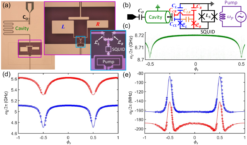
Our two-qubit system of study is displayed in Fig. 1(a) and (b) with two transmons, labelled “Left” () and “Right” (), each having a main Josephson junction and a shared two-junction SQUID parametric coupler with total inductance . Here, represents the (nonlinear) Josephson inductance for with nominally equal critical currents for the main qubit junctions, is the Josephson energy and is the magnetic flux quantum. Each transmon has capacitance (for ), with mutual capacitance . The two qubits also share the same readout cavity, each capacitively coupled through (for ), which also serves as the qubit drive line through the cavity coupling capacitor to the feedline. This leads to a very weak tunable cavity frequency that is periodic in the coupler’s static flux bias . Our compact layout only requires two on-chip ports for the whole system, one for the single element excitations plus readout, and one for setting all static operating frequencies (static coupler bias) and for generating all coupled interactions (r.f. coupler “pump” drive). This type of architecture can be extended by adding more qubits or cavities to the coupler, without increasing the number of on-chip control and readout ports.[15, 17] In Fig. 1(d), we see that the two qubits are quite closely packed in frequency space and tune with in unison, so their frequencies will never collide. Here, we denote their frequencies as and , which represents the transition from the full ground state to the joint two-qubit energy levels and , respectively (see Fig. 2(c) for more details). The shared SQUID provides only a mild tunability of the two transmons, where the two nominally equal SQUID junctions are each about , resulting in an inductive participation ratio of only a few percent at zero flux bias. The system is designed to operate at a fixed static flux, where the two qubit frequencies are fixed as well, along with the static coupling between them. This mild tunability balances our ability to provide strong parametric interactions ( MHz), allowing us to perform two-qubit gates quickly, while still minimizing either qubit’s susceptibility (GHz/) to flux noise in the SQUID.[41, 42, 15] In Fig. 1(e), we see that the anharmonicity (for ) of the two transmons is roughly constant accept for a sharp decrease as increases rapidly near . Our device design differs considerably from most current coupler designs that usually incorporate a capacitively coupled SQUID that acts more like a tunable qubit or resonator between the qubits. In contrast, our SQUID coupler is fully integrated galvanically into the qubits themselves and its self-resonance frequency is GHz for all , too high to be excited during coupled operations (see SM). This also means that the coupler’s resonant frequency will not collide with nearby qubits or cavities and no additional degrees of freedom, internal coupler dynamics, or decoherence channels come into play that could perturb its operation if not carefully taken into account.
Our device design also takes advantage of the relatively large mutual capacitance between the two closely spaced transmons to largely cancel out the mutual inductive coupling due to the SQUID coupler. The and qubit electrodes are designed in size, orientation, and separation so that the negative capacitive coupling equals the positive inductive coupling of the SQUID at the static “cancellation flux” bias, , where parametric coupling strengths will be strong. At a flux bias far from , the residual static coupling between the qubits is predominantly capacitive when or inductive when . Because the SQUID coupler is fully integrated, when the two qubits (with , for ) are very strongly coupled () with a static detuning of GHz, there is a very strong static -coupling between them[6, 43],
| (1) |
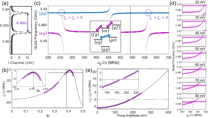
In Fig. 2(a), we show an example of weak -coupling near at , where MHz, and in (b), we show as a function of , where MHz at or . Notice that Eq. 1 only captures the induced nonlinear interactions from the static linear coupling between the two detuned qubits, which should go to zero at . However, we see that at we have MHz. This is due to the purely nonlinear coupling that results from a small fraction of the transmon’s current passing through the transmon’s main qubit junction and vise-versa. Using our design layout, Ansys Q3D, and the “scQubits” package[44, 45], we find very good agreement between our numerical predictions (solid lines) and the experimental data (circles) in Fig. 1(d),(e) and Fig. 2(b), including the residual at (see SM for more details).
With the qubits detuned by , energy exchange between two-qubit energy levels with an equal number of excitations is suppressed. The joint two-transmon levels are labelled , denoting the individual and transmon levels as , , , (see Fig. 2(c)). However, if in addition to the static flux bias , we drive the SQUID coupler with a cosinusoidal flux modulation, , then we can generate new coupling terms between any two of the two-qubit states and written in an interaction frame with respect to the free Hamiltonian[21],
| (2) |
where we will ignore sum frequency or counter-rotating terms, () is the creation (annihilation) operator of the th transmon mode, and is the difference in frequency or detuning between the higher ‘top’ level and the lower ‘bottom’ level . Here, we focus on , where is the detuning from the difference frequency . The parametric coupling strength is related to the flux dependent static coupling strength[21] through (see SM). Of course, under ideal conditions , while . It is clear from Eq. (2) that when , so that provides a swap interaction between the qubits. In general, the pump frequency can be detuned by in order to sweep between parametrically-induced resonant-type () and dispersive-type () interactions near the transition between the states and .
This behavior can been seen in the continuous frequency domain (see Fig. 2(c)) by measuring the spectrum of the qubit following a delay after -pulsing the qubit (see SM). When starting from with a fixed pump amplitude of 20 mV (generator output) and various , we see that an avoided crossing is clearly visible with a coupling strength MHz. This occurs when the two parametrically interacting states are and and , exchanging the single excitation manifold of states. When starting from , first we notice that the spectrum is shifted by MHz, with a line-cut of both peaks shown in Fig. 2(a). Then, as the pump tone increases from MHz, an avoided crossing appears when and the two parametrically connected states are and . And, lastly when , the interaction is between states and . These two splittings occur for parametric interactions within the two-photon excitation manifold of states.
The presence of the residual coupling near gives us an opportunity to show the versatility of our parametric coupling scheme by allowing us to use the parametric dispersive shifts to cancel .[15, 32] Recall that the presence of shifts the two-qubit energy level spectrum (shown in the inset of Fig. 2(c)), so that the position of satisfies the relation . Notice, in Fig. 2(c), that there are two values for where the spectroscopic peaks for initial states and cross, as denoted by the circles. This occurs when the total coupling . The parametrically induced dispersive shifts , analogous to the static case, follow from Eq. (1) with the reassignments: and . And, according to Eq. (1), as we increase the pump amplitude , increases and the value for the detuning that cancels must also increase as well. This is observed in Fig. 2(d), as the cancellation point (dashed vertical line) moves increasingly to the left of . In addition, careful observation shows a clear decrease in the frequency of the spectroscopic line corresponding to the initial state as the pump amplitude increases due to a rectification effect from the curvature of the curves (see Fig. 1(d) and the SM). If we choose an that is maximally detuned from both parametric transitions from the single () and double () manifold of states, we can avoid unwanted swap interactions (as discussed below) and ensure purely dispersive shifts that can fully cancel . An example is shown in Fig. 2(e), where we plot the total effective coupling as a function of pump amplitude for MHz, vertical dashed line in Fig. 2(c). Here, we begin at MHz, then increase as until the spectroscopic peaks merge and we cross zero coupling. If we continue to increase the pump amplitude , continues to increase as and dominates, leading to progressively stronger positive -coupling.
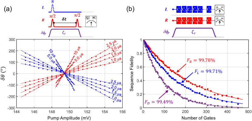
Due to the scatter in the spectroscopic data, the quadratic fit allows us to identify zero coupling with an uncertainty of about kHz. In order to improve this by an order-of-magnitude, we use cross-Ramsey-measurements[46] on the () qubit, whose phase evolution depends on the state of the () qubit and the size of the residual coupling. In this experiment, the delay time between the two pulses on the qubit are fixed at , while the phase difference on the second pulse spans producing a sine-wave. We perform this experiment on the () qubit with and without the pulse on the () qubit and measure the phase difference between these two measurements as a function of the pump amplitude around the cancellation point predicted by the spectroscopic data in Fig. 2(e). As seen in Fig. 3(a), the resulting phase difference, , shows a linear dependence on pump amplitude and passes through zero. These more sensitive cross-Ramsey measurements were performed on both qubits for several showing all curves passing through a single pump amplitude that ensures kHz. As a further verification, we performed randomized benchmarking[47] (RB) on both qubits simultaneously, as another sensitive test of residual -coupling.[46] As shown in Fig. 3(b), we find that the error per gate for simultaneous RB, where we measure the probability that we properly returned to , is equal to the sum of the individual error rates found from single qubit RB, which indicates that additional correlated errors from residual coupling is negligible (see SM).
Next, we show parametric interactions between the two qubits in the time domain, which leads us to performing specific gate operations. By applying a coherent pump signal in the vicinity of , parametric coupling induces transitions between the states and in a similar way to standard Rabi oscillations.[20, 21] The probability of being in the initially empty state over time is given by,
| (3) |
where is the parametric swap frequency when . When , the on resonance (in the rotating frame) swap frequency is , which is equal to the total mode splitting size seen in the spectroscopic data. Also, notice that the probability amplitude of these oscillations reaches unity only when . This will be important later when we discuss sources of gate errors. An example of these parametric oscillations is shown in Fig. 4(a) and (b) between states and and and , respectively. The characteristic shape due to Eq. (3) is most visible in Fig. 4(b). Line-cuts with a higher density of points were taken through the center of these data when . Fig. 4(a) shows a maximum swap frequency of MHz and Fig. 4(b) shows MHz. This provides the speed necessary to perform fast two-qubit iSWAP or c gates in about 10–40 ns. Although we performed iSWAP gates utilizing states and up to a fidelity of 99%, as detailed in the Supplemental Material, we choose to focus our attention on the c gates described below.
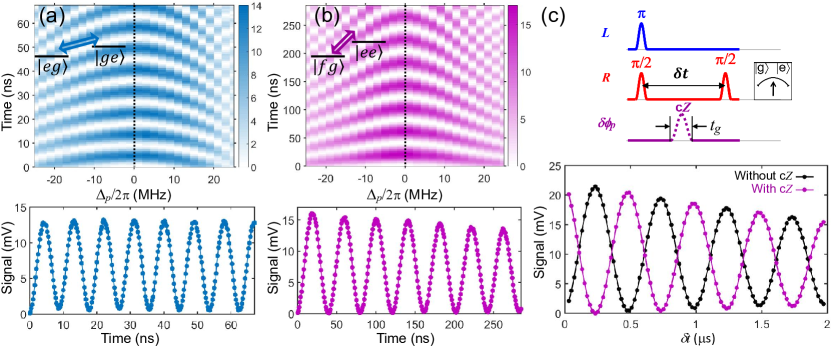
Now, let us consider a swap-induced parametric controlled-Z (p-swap c) gate[48], which can be realized via a complete rotation from the state to one of the other two-photon excited manifold of states or and back to . Parametric two-qubit gates using similar principles have been realized with other systems[27, 25, 14], but with either limited parametric coupling strength [25, 14] or reduced coherence times [27]. As we will see, our parametric coupling strategy can balance high gate speeds with relatively long qubit coherence times, leading to a large ratio for the coherence time to gate duration, minimizing gate errors in the presence of uncorrelated qubit decoherence. We show in Fig. 4(c) a simple demonstration of a p-swap c gate. Here, we perform a cross-Ramsey experiment on the qubit with a -pulse on the qubit with and without a c gate applied half-way between the cross-Ramsey sequence. As expected, we observe a phase shift between the two possible Ramsey oscillations. Cross-Ramsey experiments are helpful in the calibration procedures for optimizing the c gates, because the rectification of the qubit frequencies is dependent on and (see SM).
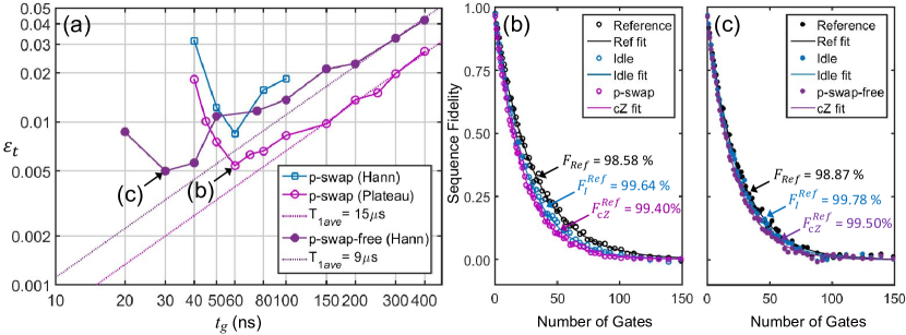
To quantify the p-swap c gate fidelity, we perform standard interleaved RB.[49]. In Fig. 5(a), we show the measured total error per gate as a function of the gate duration (see pulse diagram in Fig. 4(c), as is defined by the edge-to-edge pulse width), where we first focus on pulse envelopes made from two fixed 20 ns Hann function rise and fall pulse edges plus a variable length plateau. For each gate duration, we have performed a suite of calibrations and use RB[50] plus a covariance matrix adaptation evolution strategy (CMA-ES) for numerical optimization[51] of the gate performance (see SM). In general, the total error per gate can be broken into decoherence-induced errors and any control errors , which could include noise in the control electronics or coherent evolutions from unintended Hamiltonian dynamics. We observe that when the gate duration is long ( ns), the error rate is dominated by the average qubit energy decay rate, or , with , as shown by the dotted line in Fig. 5(a) for s. This suggests that as decreases with respect to , the gate error should decrease steadily towards zero. However, our experimental results show that as decreases, the observed deviates from the decoherence line when increases, reaching a minimum value at ns, until eventually dominates the total error for the shortest gate durations. As a result, we achieve our best p-swap c gate fidelity of 99.4% with a gate duration of ns, as shown in Fig. 5(b). We can also compare this to the fidelity of an idle gate in place of the p-swap c gate, which is slightly improved at 99.6%, showing that .
In order to investigate sources for , we carried out a series of gate fidelity measurements with variations in the shape of the gate’s pump pulse envelope. Notice that at ns the pulse envelope is made from equal durations of Hann function pulse edges and a plateau. As the pulse width decreases from here, the spectrum of these pulses in frequency space becomes wider, following more closely the Fourier transform of a pure Hann pulse once ns, which is a broadened version of a rectangular window function. Thus, if a narrowing spectral width (decreasing ) leads to leakage errors as a limiting factor (increasing ), then the pure Hann pulses would improve our gate fidelity. However, experiments show the opposite. First, we independently verified that leakage to higher transmon levels was not a significant source of error (see SM). Next, we carried out c gate experiments where the pump pulse envelope was a pure Hann function of different widths, as shown in Fig. 5(a). Notice that this group of data has a total error per gate systematically higher than the experiments with plateaued pulses for the same qubit coherence.
We can understand the source of these errors by returning to the concept of how this gate works. Ideally, starting from the state, the parametric pump pulse operates at exactly , so that the state evolution under the Hamiltonian (from Eq. (2)) occurs at the center of the Rabi curve (from Eq. (3) shown in Fig. 4(a)) returning all of the state population back to with a final phase accumulation of exactly . In reality, because the frequencies of both qubits, their anharmonicities, and all experience a slight adjustment due to the rectification effect that depends on pump amplitude and frequency , it is difficult to maintain a perfect evolution of the states and cancellation of (see SM). For our experiments, we choose a fixed cancellation tone for to ensure proper single qubit gates in the absence of any gate tones. For the gate tone, we use a constant frequency set according to the rectified values of the two-qubit states at the maximum pump amplitude, as measured during parametric Rabi oscillations as we sweep (see for example Fig. 4 and SM). Thus, during the rise and fall of the Hann pulse envelope, the frequency is slightly detuned from optimal. For low amplitude pump pulses mostly comprised of a pulse plateau (larger ), the evolution of the gate matches closely with the idealized case and the residual coupling is still negligible. On the contrary, for pure Hann pulses, the pump frequency only matches at the maximum amplitude of the pulse, modifying the Hamiltonian evolution of the gate (recall Eq. (3)). In addition, as the pulse amplitude increases for shorter , the static tone is not completely cancelling during the gate, although this effect is compensated for by the reduced gate duration over which it occurs. These problems could be properly addressed by varying the drive frequency and cancellation tone over the duration of the gate, which we plan to explore in future experiments.
In order to remedy these issues, we next turn to a parametric c gate that is swap-free. A nice feature of the p-swap-free c gate is that there is no requirement to optimize a single parametric drive frequency, making this gate more resilient to rectification-induced errors. Recall in Fig. 2(e), we could just cancel or choose to drive harder so that , producing strong positive -coupling. This is a much more natural way to realize a c gate[9], where a net frequency shift of the state over time can accumulate the necessary conditional phase,
| (4) |
To perform the gate, we add an additional tone along with the constant cancellation tone , so . Any slight deviations over time in during the gate pulse due to rectification may lead to distortions so that is not optimal, but we only require the integral in Eq. (4) to be satisfied. As a first approximation, this can be compensated by a small increase or decrease in the gate duration. This means that we can use pure Hann pulses without any plateau and not suffer from additional errors from pump-induced rectification. After performing a suite of calibrations and using CMA-ES (see SM), we measured for various , in a similar way as for the p-swap c gate. We find that for long gate durations, the p-swap-free c gate is limited by the combined decoherence of the two qubits, which was s for this particular cooldown (see SM). Again, as is reduced the fidelity increases initially following the decoherence prediction and then begins to deviate. The minimum gate error is observed to be 99.5% with a pure Hann pulse with total rise and fall time of 30 ns, as is shown in Fig. 5(c). We believe this is the fastest and highest fidelity gate achieved with on-chip parametric coupling to date.
For both the p-swap and p-swap-free c gates, the gate error rises rapidly for the shortest gate durations. To investigate this we performed some high amplitude pump drive tests, where the initial two-qubit state was not one of the parametrically connected states or (see SM). We found that it is possible for the parametric pump to drive multi-photon induced single qubit transitions when , where is the number of photons absorbed. For the highest pump amplitudes, if was in the vicinity of these frequencies, the pump can cause unwanted single qubit Rabi rotations. In principle, these coherent single qubit errors could be nulled out with additional deterministic single qubit drives that could counteract these stray rotations. In future designs, we plan to significantly decrease the capacitive coupling between the bias coil and the transmons in order to reduce any direct driving and resultant multi-photon absorption (see SM).
To conclude, we have demonstrated a versatile, hardware-efficient, fast, and high-performance parametric coupler between two mildly tunable transmon qubits. We are able to eliminate stray coupling between the two qubits and performed three types of two-qubit gates: p-iSWAP, p-swap c, and p-swap-free c. We measured gate error as a function of gate duration and found an optimized gate fidelity of 99.4% and 99.5% for the p-swap and p-swap-free c gates, respectively. For longer gate durations above 100 ns, the gate error is almost entirely limited by qubit decoherence, while the shortest gates are limited by erroneous Hamiltonian evolutions. Exploring different pulse shapes indicates that a significant portion of the control errors in the p-swap c gate can be ascribed to a rectification effect, which can be largely avoided when performing p-swap-free c gates. Our results suggest that modest improvements in qubit coherence in next generation devices should lead to parametric two-qubit gates with fidelities beyond 99.9%. These concepts can scaled into integrated multi-qubit cavity QED systems to provide in-situ parity readout useful for error correction.[15]
Acknowledgements
This work was partially performed under financial assistance from U.S. Department of Commerce, National Institute of Standards and Technology. Eliot Kapit’s work was supported by NSF grant PHY-1653820 and ARO grant No. W911NF-18-1-0125. We thank Frederick W. Strauch for useful discussions and suggestions for improving gate fidelity in the experiments. We thank Manuel C. Castellanos-Beltran and Joshua Combes for commenting on the manuscript.
Author contributions
X.Y.J. conducted the experiment. X.Y.J., Z.P. and R.W.S. analyzed and modelled the data. R.W.S. designed and K.C. fabricated the device. S.K. contributed to the measurement set-up and software. E.K. provided theoretical support and suggestions for the experiment. X.Y.J. and R.W.S. wrote the manuscript and supplemental material. R.W.S. conceived the experiment and supervised the project. All authors contributed to the preparation of the manuscript.
References
- [1] Shor, P. W. Algorithms for quantum computation: Discrete logarithms and factoring. In Proceedings of the 35th Annual Symposium on Foundations of Computer Science, 124–134 (1994).
- [2] Nielsen, M. A. & Chuang, I. L. Quantum Computation and Quantum Information (Cambridge University Press, 2010).
- [3] Arute, F. et al. Quantum supremacy using a programmable superconducting processor. Nature 574, 505–510 (2019).
- [4] Gaebler, J. P. et al. High-fidelity universal gate set for 9be+ ion qubits. Phys. Rev. Lett. 117, 060505 (2016).
- [5] Monroe, C., Kim, J., Noh, C. & Vahala, K. Programmable quantum computers. Nature 591, 198–205 (2021).
- [6] Barends, R. et al. Superconducting quantum circuits at the surface code threshold for fault tolerance. Nature 508, 500–503 (2014).
- [7] Kelly, J. et al. State preservation by repetitive error detection in a superconducting quantum circuit. Nature 519, 66–69 (2015).
- [8] Sung, Y. et al. Realization of high-fidelity cz and zz-free iswap gates with a tunable coupler. Physical Review X 11, 021058 (2021).
- [9] Stehlik, J. et al. Tunable coupling architecture for fixed-frequency transmon superconducting qubits. Physical Review Letters 127, 080505 (2021).
- [10] Xu, Y. et al. High-fidelity, high-scalability two-qubit gate scheme for superconducting qubits. Physical Review Letters 125, 240503 (2020).
- [11] Moskalenko, I. N. et al. High fidelity two-qubit gates on fluxoniums using a tunable coupler. npj Quantum Information 8, 130 (2022).
- [12] Marxer, F. et al. Long-distance transmon coupler with cz-gate fidelity above 99.8%. PRX Quantum 4, 010314 (2023).
- [13] Ding, L. et al. High-fidelity, frequency-flexible two-qubit fluxonium gates with a transmon coupler. Arxiv: 2304.06087 (2023).
- [14] Reagor, M. et al. Demonstration of universal parametric entangling gates on a multi-qubit lattice. Science advances 4, eaao3603 (2018).
- [15] Noh, T. et al. Strong parametric dispersive shifts in a statically decoupled multi-qubit cavity qed system. Arxiv: 2103.09277 (2021).
- [16] Zhou, C. et al. A modular quantum computer based on a quantum state router. Arxiv: 2109.06848 (2021).
- [17] Brown, T. et al. Trade off-free entanglement stabilization in a superconducting qutrit-qubit system. Nature Communications 13, 3994 (2022).
- [18] Paolo, A. D. et al. Extensible circuit-qed architecture via amplitude- and frequency-variable microwaves. Arxiv: 2204.08098 (2022).
- [19] Marinelli, B. et al. Dynamically reconfigurable photon exchange in a superconducting quantum processor. Arxiv: 2204.08098 (2023).
- [20] Zakka-Bajjani, E. et al. Quantum superposition of a single microwave photon in two different ’colour’ states. Nature Physics 7, 599–603 (2011).
- [21] Allman, M. et al. Tunable resonant and nonresonant interactions between a phase qubit and lc resonator. Physical Review Letters 112, 123601 (2014).
- [22] Lu, Y. et al. A high-fidelity microwave beamsplitter with a parity-protected converter. Arxiv: 2303.00959 (2023).
- [23] Didier, N. et al. Parametrically activated entangling gates using transmon qubits. Physical Review A 97, 022330 (2018).
- [24] Li, X. et al. Perfect quantum state transfer in a superconducting qubit chain with parametrically tunable couplings. Phys. Rev. Applied 10, 054009 (2018).
- [25] Ganzhorn, M. et al. Benchmarking the noise sensitivity of different parametric two-qubit gates in a single superconducting quantum computing platform. Phys. Rev. Research 2, 033447 (2020).
- [26] Hong, S. S. et al. Demonstration of a parametrically activated entangling gate protected from flux noise. Phys. Rev. A 101, 012302 (2020).
- [27] Noguchi, A. et al. Fast parametric two-qubit gates with suppressed residual interaction using the second-order nonlinearity of a cubic transmon. Phys. Rev. A 102, 062408 (2020).
- [28] Shaowei Li, et. al.. Realization of fast all-microwave cz gates with a tunable coupler. Chin. Phys. Lett. 39, 030302 (2022).
- [29] Roy, T., Li, Z., Kapit, E. & Schuster, D. I. Realization of two-qutrit quantum algorithms on a programmable superconducting processor. Arxiv: 2211.06523 (2022).
- [30] Petrescu, A. et al. Accurate methods for the analysis of strong-drive effects in parametric gates. Phys. Rev. Applied 19, 044003 (2023).
- [31] Lu, Y. et al. Universal stabilization of a parametrically coupled qubit. Physical Review Letters 119, 150502 (2017).
- [32] Pérez, D. R. et al. Error-divisible two-qubit gates. Physical Review Applied 19, 024043 (2023).
- [33] Li, Z. et al. Autonomous error correction of a single logical qubit using two transmons. Arxiv: 2302.06707 (2023).
- [34] Li, Z., Roy, T., Pérez, D. R., Schuster, D. I. & Kapit, E. Hardware efficient autonomous error correction with linear couplers in superconducting circuits. Arxiv: 2303.01110 (2023).
- [35] Yurke, B. et al. Observation of parametric amplification and deamplification in a josephson parametric amplifier. Physical Review A 39, 2519 (1989).
- [36] Tian, L., Allman, M. S. & Simmonds, R. W. Parametric coupling between macroscopic quantum resonators. New Journal Of Physics 10 (2008).
- [37] Teufel, J. D. et al. Sideband cooling of micromechanical motion to the quantum ground state. Nature 475, 359–363 (2011).
- [38] Ranzani, L. & Aumentado, J. Graph-based analysis of nonreciprocity in coupled mode system. New J. Phys. 17, 023024 (2015).
- [39] Gambetta, J. M., Chow, J. M. & Steffen, M. Building logical qubits in a superconducting quantum computing system. npj Quantum Information 3, 1–10 (2017).
- [40] Preskill, J. Quantum computing in the nisq era and beyond. Quantum 2, 79 (2018).
- [41] Hutchings, M. D. et al. Tunable superconducting qubits with flux-independent coherence. Phys. Rev. Applied 8, 044003 (2017).
- [42] Chávez-Garcia, J. M. et al. Weakly flux-tunable superconducting qubit. Phys. Rev. Applied 18, 034057 (2022).
- [43] Long, J. et al. A universal quantum gate set for transmon qubits with strong zz interactions. arXiv: 2103.12305 (2021).
- [44] Groszkowski, P. & Koch, J. Scqubits: a python package for superconducting qubits. Quantum 5, 583 (2021).
- [45] Chitta, S. P., Zhao, T., Huang, Z., Mondragon-Shem, I. & Koch, J. Computer-aided quantization and numerical analysis of superconducting circuits. New Journal of Physics 24, 103020 (2022).
- [46] Mundada, P., Zhang, G., Hazard, T. & Houck, A. Suppression of qubit crosstalk in a tunable coupling superconducting circuit. Phys. Rev. Applied 12, 054023 (2019).
- [47] Knill, E. et al. Randomized benchmarking of quantum gates. Phys. Rev. A 77, 012307 (2008).
- [48] Strauch, F. W. et al. Quantum logic gates for coupled superconducting phase qubits. Phys. Rev. Lett. 91, 167005 (2003).
- [49] Córcoles, A. D. et al. Process verification of two-qubit quantum gates by randomized benchmarking. Phys. Rev. A 87, 030301(R) (2013).
- [50] Kelly, J. et al. Optimal quantum control using randomized benchmarking. Phys. Rev. Lett. 112, 240504 (2014).
- [51] Werninghaus, M. et al. Leakage reduction in fast superconducting qubit gates via optimal control. npj Quantum Information 7, 14 (2021).
Methods
The samples were fabricated on 76 mm sapphire wafers. The main wiring layer is formed by a fluorine-based reactive ion, dry gas etch of a 100 nm thick sputtered niobium film. Next, Josephson junctions are fabricated using the well known “Dolan bridge technique” that relies on a double-angle () evaporation of aluminum using a bi-layer resist stack consisting of MMA/PMMA (550 nm/240 nm), with an intermediate step for oxidization (100 mTorr for 300 seconds) of the first layer of aluminum (35 nm). The second deposition provides the top aluminum layer (75 nm) and forms a tunnel barrier across a narrow overlap region forming the Josephson junctions (qubit junction areas were approximately 100 nm 120 nm, while SQUID junctions were approximately ). This was achieved in a custom deposition chamber with a load-lock that allows computer controlled oxidization for creating reproducible junction current densities. The final step requires connecting the Josephson junctions to the niobium wiring layer through an aluminum patch layer that is e-beam evaporated in the same chamber that was used for making junctions and then lifted off. To ensure superconducting contacts between all layers, we use an ion mill cleaning step (beam = 300 V, accelerator = 950 V, filament = 3.47 A) for 30 seconds before depositing aluminum.
Once diced, the chips are mounted into a sample box made of aluminum and bonded directly to non-magnetic microwave SMA bulkhead feedthrus for wiring connections, with additional bond wires between the ground plane on the chip and the inside of the box. This aluminum box is then placed inside another copper box of cylindrical shape. A niobium tube is then placed over this cylinder and is thermalized by a copper tube that covers it. A -metal tube is then placed over this cylinder with another copper tube over that for thermalization. Finally, a copper can lined with black carbonized foam encloses all these layers. The coaxial cables are routed out of the ends of the cylinders and into non-magnetic SMA feedthrus that pass through the copper can. The entire shielded enclosure is mounted to the bottom of a dilution refrigerator and cooled to 10 mK. For more details on the experimental setup, see Supplementary Section I.
Supplementary Information
Coming soon…