A Resonant Tank Based Approach for Realizing ZPA in Inductive Power Transfer Systems
Abstract
A load-independent constant current (CC) - constant voltage (CV) output is an important requirement of inductive power transfer (IPT) systems for electric vehicle charging applications. Zero phase angle (ZPA) is also a desirable feature, to ensure a lower power rating requirement for the switching converter. CC and CV output along with ZPA can be achieved by using a suitable compensation topology. Equation manipulation techniques can be used for designing the compensation topology. But, it can be mathematically intensive especially for higher order topologies. To overcome this problem, resonant-tank based approaches are adopted in several works to achieve CC and CV conditions. However, equation-based approaches are depended upon either wholly or partly for realizing ZPA. This approach can be tedious and lacks physical insight. The proposed method extends resonant tank approach to achieve ZPA also, besides CC and CV. The need for a separate method to achieve ZPA is eliminated. Further, it simplifies the process in arriving at the constraints that ensure ZPA. As a sample validation, the proposed method is applied to a S-SP compensation topology. The CC-ZPA and CV-ZPA constraints for the S-SP topology are shown to be in line with the ones arrived at using an existing equation-based impedance approach. The simplicity of the proposed method can be observed from the sample validation.
Index Terms:
inductive power transfer (IPT), compensation network, constant current (CC), constant voltage (CV), zero phase angle (ZPA)I Introduction
Static wireless inductive power transfer (IPT) for electric vehicle (EV) charging has several advantages compared to plug-in charging in terms of better safety, lesser maintenance requirement, etc. EVs generally use Li-ion batteries due to their high power densities. Constant current (CC)- constant voltage (CV) charging is the suitable charging method for Li-ion. Further, zero phase angle (ZPA) is desirable to ensure a lower power rating requirement for the switching converter. Some of the compensation topologies can be operated at two different frequencies to achieve CC and CV outputs along with ZPA in both modes. Different methods have been proposed for identifying the constraints to achieve CC and CV along with ZPA [1, 4, 5, 6].
I-A A brief survey of CC-CV and ZPA methods
CC-CV output can be achieved using passive resonant networks. [1] discusses that a T, reversed-L, normal-L and network can be used to achieve voltage-voltage (V-V), voltage-current (V-C), current-voltage (C-V) and current-current (C-C) conversions respectively by satisfying certain resonant conditions as given in Fig. 1. A compensation topology can be regarded as a cascade of these four basic resonant networks in order to understand its CC-CV functionality.
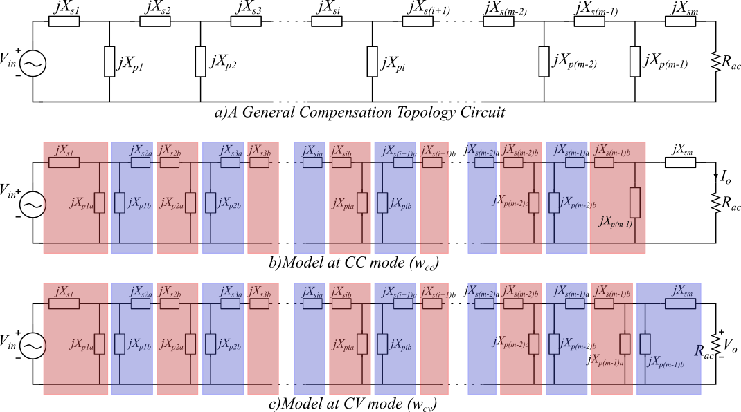
Further, [4] points out that even a T- network and a pi-network can be regarded as a combination of normal L-network and reversed L-network. Thus the entire compensation circuit can be disintegrated into normal and reversed L-networks cascaded alternatively as in Fig. 2 . A V-V conversion and a C-C conversion will require an even number of such L-networks, and a V-C conversion and a C-V conversion will require an odd number of L-networks.
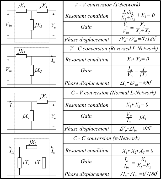
Each L-network, normal or reversed, adds a phase of between corresponding output and input quantities (Fig. 1). Since a V-V conversion requires an even number of resonant L-networks cascaded together, the output voltage () will always be shifted by a phase of or with respect to the input voltage (). Similarly in a C-C conversion, the output and input currents are always displaced by or . In C-V and V-C conversions, the corresponding output and input quantities are always phase displaced by since an odd number of L-networks is used.
For achieving ZPA, different methods are proposed by references [1, 4, 5]. Reference [1] discusses that ZPA can be achieved by making the imaginary part of the input impedance () zero. This condition, , can be solved mathematically for any topology but it becomes tedious for higher order topologies. Reference [4] proposes a general mathematical equation to achieve ZPA which works for any topology. The advantage of this method is that the impedances can be directly plugged in instead of deriving the condition from the first principles for every topology. However the equation is still complicated, especially for higher order topologies. Reference [5] proposes the use of a T-network with their impedances satisfying a certain condition such that the input impedance becomes purely resistive. A compensation topology can be seen as a cascade of such T-networks. This greatly reduces the computational effort required to solve a complicated mathematical equation. However, this method of achieving ZPA can be applied for only one mode, either CC or CV mode and the ZPA condition for the other mode has to be mathematically derived. Reference [6] models the topology using gyrators to achieve CC-CV functionality and qualitatively comments on the sign of the input phase angle.
In the proposed approach the ZPA condition is obtained by applying the resonant tank methods of [1, 4] which were till now used only to achieve CC-CV. Thus ZPA and CC-CV conditions can be seen from the same perspective and the need for a separate method to obtain ZPA is eliminated. Further, the proposed approach simplifies the process of arriving at the condition for ZPA. The equations that ensure ZPA can be written from the fundamental equations listed in Fig. 1.
II Principle of achieving ZPA
An input voltage source requires a compensation topology with V-V conversion to achieve a CV mode. As pointed out in Section-I the phase of output voltage () and input voltage () will be displaced by (Fig. 1).
| (1) |
Now, if the compensation topology is designed to achieve C-C conversion along with V-V conversion, the phase of output current() and the input current() will also be displaced by (Fig. 1).
| (2) |
Then, we have either
| (3) |
or
| (4) |
The output port of the compensation topology which consists of a rectifier, a filter and the load can be modelled as an equivalent ac resistance [5]. The load being an equivalent resistance , will be . If (3) is true, it would mean that power is being supplied to both the input and the output by the compensation network, which is not possible since the compensation network is just a combination of passive elements. This power flow constraint requires (3) to be true and not (4). So, and ZPA is achieved.
Similarly in CC mode, if we ensure not only V-C conversion but also C-V conversion, is equal to and ZPA can be achieved along with CC.
| (5) | ||||
| (6) | ||||
| (7) |
III Sample illustration of proposed approach
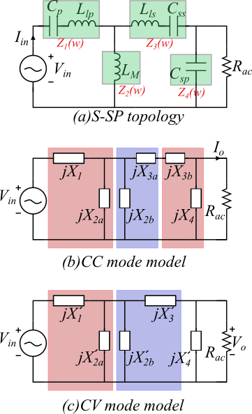
The proposed method for arriving at ZPA conditions is illustrated using a series – series parallel (S-SP) topology in this section. A S-SP topology has a series compensation capacitor () in the primary side, and a series capacitor () and a parallel capacitor () in the secondary side as shown in Fig 3(a). , , and denote the primary and secondary leakage inductances and the magnetizing inductance of the wireless power transfer coil. The topology can be represented as in Fig 3(a) with impedances to listed in (8) to (11). Let and denote the CC mode and CV mode resonant frequencies. Let represent the impedances in CC mode and represent the impedances in CV mode as shown in (12) and (13).
| (8) | ||||
| (9) | ||||
| (10) | ||||
| (11) | ||||
| (12) | ||||
| (13) |
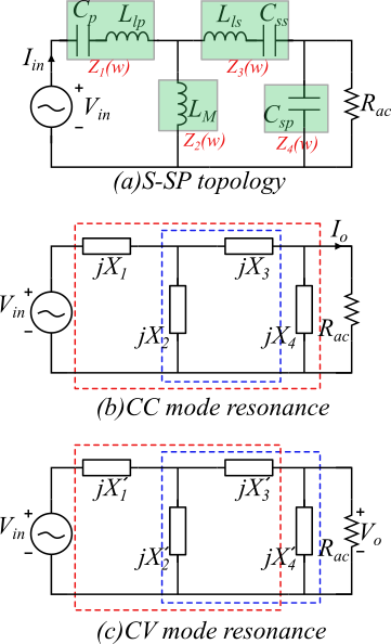
In Fig. 3, the elements that need to be resonated to achieve CC/CV and the corresponding ZPA condition are shown in red and blue boxes respectively.
III-A Conditions in CC mode
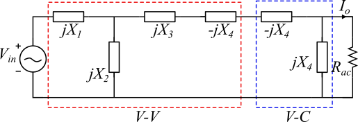
The CC mode can be obtained by resonating the components inside the red box in Fig. 3(b). From Fig. 1, the required resonant condition is (14). This can be understood by redrawing the circuit as shown in Fig. 4. The redrawn circuit is equivalent to Fig. 3(b) and can be viewed as a cascaded combination of a V-V conversion and V-C conversion. The V-C conversion does not depend on the value of since any value of will satisfy the resonant condition for a reversed L-network given in Fig. 1.
For ZPA condition, along with V-C (CC operation), C-V conversion is also required. Now, in order to achieve C-V conversion, the normal L-network consisting and can be resonated as (15).
| (14) | ||||
| (15) |
III-B Conditions in CV mode
The CV mode can be obtained by resonating the T-network in Fig. 3 consisting , , by ensuring the resonant condition (16). For ZPA condition a C-C conversion is required. This can be done by resonating the -network in Fig. 3 consisting , , by ensuring (17).
| (16) | ||||
| (17) |
IV Equivalence to impedance approach
The equation based approaches in literature [2, 3, 4] typically equate the imaginary part of the input impedance of the compensation network to zero to arrive at the ZPA condition. This section compares the CC/CV and ZPA conditions derived in Section III for a S-SP topology to an existing impedance approach [4] to show its equivalence. In [4], called the unified model, the impedances are transformed as shown in Fig. 5 where the transformed impedances are given by (18), (19) and (20). and denote the CC mode and CV mode resonant frequencies.
| (18) | ||||
| (19) | ||||
| (20) |
The resonance condition derived in [4] for CC output, ZPA at CC mode, CV output and ZPA at CV mode are given by :
| (21) | ||||
| (22) | ||||
| (23) | ||||
| (24) |
IV-A Verification in CC mode
Adding to (22) and rearranging, we get (27). This does not alter the equation since is zero from (21).
| (27) |
| (28) |
IV-B Verification in CV mode
Similarly in CV mode, using (23), the transformed variables and can be written as
| (29) |
Substituting the above equation in the expression for in (20) and rearranging, we can get the same expression as (16) for the CV resonant condition.
Adding to (24) and rearranging, we get (30). This does not alter the equation since () is zero, from (23). Dividing (30) by (), we get the ZPA condition which is the same as (17).
| (30) |
Thus, the conditions derived in this work is in agreement with the results obtained through equation based impedance approach outlined in [4]. This is expected to be true for other impedance based methods available in literature as well since the angle between the input voltage and current being zero in the proposed approach is equivalent to an input impedance that is resistive.
V Conclusion
In this paper a method to achieve ZPA condition using resonant tanks is presented. Thus CC-CV and ZPA conditions can be seen from the same lens and the need of two separate methods is eliminated. Further, the proposed approach largely simplifies the otherwise complicated equations required to arrive at the ZPA condition. The proposed method is applied for a S-SP compensation topology and the results are verified to be same as the results of [4].
References
- [1] W. Zhang and C. C. Mi, “Compensation Topologies of High-Power Wireless Power Transfer Systems,” in IEEE Transactions on Vehicular Technology, vol. 65, no. 6, pp. 4768-4778, June 2016, doi: 10.1109/TVT.2015.2454292.
- [2] V. -B. Vu, D. -H. Tran and W. Choi, “Implementation of the Constant Current and Constant Voltage Charge of Inductive Power Transfer Systems With the Double-Sided LCC Compensation Topology for Electric Vehicle Battery Charge Applications,” in IEEE Transactions on Power Electronics, vol. 33, no. 9, pp. 7398-7410, Sept. 2018, doi: 10.1109/TPEL.2017.2766605.
- [3] J. Lu, G. Zhu, D. Lin, Y. Zhang, H. Wang and C. C. Mi, “Realizing Constant Current and Constant Voltage Outputs and Input Zero Phase Angle of Wireless Power Transfer Systems With Minimum Component Counts,” in IEEE Transactions on Intelligent Transportation Systems, vol. 22, no. 1, pp. 600-610, Jan. 2021, doi: 10.1109/TITS.2020.2985658.
- [4] J. Lu, G. Zhu, D. Lin, Y. Zhang, J. Jiang and C. C. Mi, “Unified Load-Independent ZPA Analysis and Design in CC and CV Modes of Higher Order Resonant Circuits for WPT Systems,” in IEEE Transactions on Transportation Electrification, vol. 5, no. 4, pp. 977-987, Dec. 2019, doi: 10.1109/TTE.2019.2940337.
- [5] X. Qu, H. Chu, S. -C. Wong and C. K. Tse, “An IPT Battery Charger With Near Unity Power Factor and Load-Independent Constant Output Combating Design Constraints of Input Voltage and Transformer Parameters,” in IEEE Transactions on Power Electronics, vol. 34, no. 8, pp. 7719-7727, Aug. 2019, doi: 10.1109/TPEL.2018.2881207.
- [6] Y. H. Sohn, B. H. Choi, G. -H. Cho and C. T. Rim, “Gyrator-Based Analysis of Resonant Circuits in Inductive Power Transfer Systems,” in IEEE Transactions on Power Electronics, vol. 31, no. 10, pp. 6824-6843, Oct. 2016, doi: 10.1109/TPEL.2015.2506737.