Multilayer metamaterials with mixed ferromagnetic domain core and antiferromagnetic domain wall structure
Abstract
Magnetic nano-objects possess great potential for more efficient data processing, storage and neuromorphic type of applications. Using high perpendicular magnetic anisotropy synthetic antiferromagnets in the form of multilayer-based metamaterials we purposely reduce the antiferromagnetic (AF) interlayer exchange energy below the out-of-plane demagnetization energy, which controls the magnetic domain formation. As we show via macroscopic magnetometry as well as microscopic Lorentz transmission electron microscopy, in this unusual magnetic energy regime, it becomes possible to stabilize nanometer scale stripe and bubble textures consisting of ferromagnetic (FM) out-of-plane domain cores separated by AF in-plane Bloch-type domain walls. This unique coexistence of mixed FM/AF order on the nanometer scale opens so far unexplored perspectives in the architecture of magnetic domain landscapes as well as the design and functionality of individual magnetic textures, such as bubble domains with alternating chirality.
The engineering and control of the domain-wall (DW) spin structure in magnetic systems is a crucial area of research for magnetic logic and memory applications, as the dynamic properties of magnetic solitons or DWs themselves strongly depend on it. Additionally, it further impacts the response of DWs to external stimuli, such as magnetic fields and electric currents, and their interaction with other magnetic DWs Woo2016 ; Fert2017 ; Nagaosa2013 ; Jiang2017 ; Litzius2017 ; Legrand2018 ; Lucassen2019 ; Tomasello2014 ; Malozemoff79 ; Hubert2009 . In order to control the internal DW spin structure, it is attractive to use magnetic multilayer (ML) structures, where the respective magnetic energy terms can be adjusted by interfacing of different materials. For example, the locking of DW chirality, leading to skyrmion-like magnetic textures, has been realised via the interfacial Dzyaloshinskii-Moriya interaction (IDMI) Woo2016 ; Moreau2016 ; Pollard2017 . Additionally, by exploiting the Ruderman–Kittel–Kasuya–Yoshida (RKKY) type interaction Parkin1990 ; Stiles1999 , domains and DWs that are antiferromagnetically (AF) coupled across a non-magnetic spacer layer have been realized in synthetic antiferromagnets (SAFs) Yang2015 ; Dohi2019 ; Legrand2020 ; Chen2020 ; Juge2022 ; Chen2022 ; Duine2018 . Both the AF-DWs Yang2015 and skyrmion bubbles in SAFs Dohi2019 can be driven more efficiently by spin-orbit torques with much smaller current density than it is typically necessary for efficient DW movement in ferromagnetic (FM) MLs. This highlights the potential of SAFs as a promising platform for energy-efficient magnetic logic and memory devices Fattouhi2021 ; Song2020 .
Unlike the direct exchange in intrinsic antiferromagnets, the interlayer exchange coupling in SAFs () is much weaker and can be balanced with other magnetic energy terms, such as perpendicular magnetic anisotropy (PMA) () and magnetostatic dipole interaction () Hellwig2003 ; Hellwig2004 ; Hellwig2007 ; Bran2009 ; Hauet2008 ; Hellwig2011 . These terms shape the domain structure and DW spin configuration in magnetic MLs. The strength of the demagnetization energy in a uniformly magnetized ML system is highly dependent on the orientation of the magnetization with respect to the thin film geometry. When tuning the interlayer AF exchange coupling energy to be about equal to the out-of-plane demagnetization energy in a PMA-SAF system, both FM and AF phases can coexist Hellwig2003 ; Hellwig2004 ; Hellwig2007 ; Bran2009 . Furthermore, even if the demagnetization energy leads to the formation of a regular periodic FM stripe domain pattern, locally hidden AF configurations will still exist for example within the Bloch type stripe domain walls. Thus, for a demagnetization energy dominated periodic stripe domain structure with weak AF interlayer exchange coupling, out-of-plane FM domain cores will be separated by in-plane AF Bloch-type domain walls. This so far unknown mixed FM domain core and AF domain wall structure originates from the unusual maximum energy configuration (), which can be precisely controlled in the multilayer metamaterials that we employ here for its experimental implementation.
We explore SAF systems using highly tunable, application-friendly ML structures of the type {[Co/Pt]X-1/Co/Ru}N-1[Co/Pt]X, which possess strong PMA. We demonstrate that our PMA-SAF system exhibits FM behaviour with stripe and bubble domains in the ground state, similar to that observed in [Co/Pt]X reference samples. A detailed study of the DW spin structure and magnetic field behaviour in the PMA-SAFs, however, shows that the Bloch-type DWs possess an AF ordering in-depth. The observation of AF-DWs between FM domains is consistent with the results of micromagnetic simulations (Fig.1e,f). These results extend the spin configuration possibilities for magnetic solitons and provide a way to control and design the internal DW spin structure, which is a key ingredient that defines the dynamic limits for race-track-type applications.
Multilayer metamaterial system
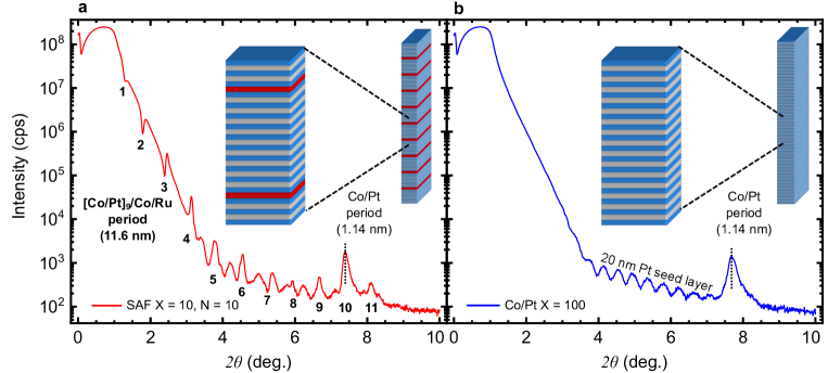
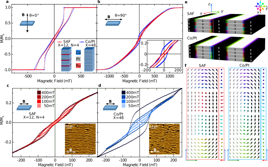
In order to demonstrate the key differences between PMA-SAFs and magnetic MLs with PMA, we fabricated two different sets of samples as schematically depicted in the inset of Fig.1a. The first set (we refer to as SAF) consists of {[Co(0.44 nm)/Pt(0.7 nm)]X-1/Co(0.44 nm)/Ru(0.9 nm)}N-1[Co(0.44 nm)/Pt(0.7 nm)]X with (or ). The second set (we refer to as Co/Pt) consists of [Co(0.44 nm)/Pt(0.7 nm)]X PMA-MLs with = 48 (or 100). The thicknesses of the Co and Pt layers (given in parentheses) were chosen to provide strong PMA (see the Methods section). The thickness of the Ru-layer was adjusted for the strongest AF coupling between the Co-layers, which has an oscillatory dependence on the Ru thickness due to the RKKY-type interaction Parkin1990 ; Stiles1999 . The structural comparison of PMA-SAF and PMA-FM systems is provided in the Extended Data Fig.1a,b
Macroscopic magnetization averaged characterization
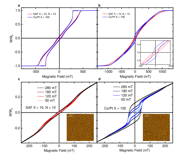
The magnetic hysteresis loops of two samples, SAF and Co/Pt = 48 are compared in Fig.1a,b. The out-of-plane magnetization measurements (Fig.1a) reveal identical easy-axis behaviour for both samples, indicating that the magnetization reversal mechanism via domain nucleation and annihilation is identical in both systems. Thus, the SAF sample exhibits PMA ferromagnetic characteristics as well. However, the in-plane magnetization measurements (Fig.1b), when carefully examined reveal a distinct difference in their hard-axis behavior at remanence (zero magnetic field). Specifically, the Co/Pt sample exhibits a non-zero remanent moment, while the SAF sample has almost no remanence as shown in the inset of Fig.1b. The nonzero remanent moment in Co/Pt is caused by the magnetization within Bloch-type DWs, which separate stripe domains formed at the magnetization reversal, as reported in Ref.[ Salikhov2021 ]. Consequently, the vanishing remanence in the SAF system indicates the absence of the net magnetization from the Bloch-type DWs. A similar behaviour is observed when comparing the SAF system with the respective Co/Pt = 100 ML sample ( Extended Data Fig.2a,b).
Owing to the fact that the remanent in-plane magnetization originates from the Bloch-type DW polarization, one can study the characteristics of the DW magnetic switching using magnetometry Salikhov2021 . To stabilize the aligned stripe-domain state in all samples, an in-plane ac-demagnetization (ACD) protocol is employed (details can be found in the Methods section). After ACD, both systems exhibit parallel stripe domains aligned along the direction of the ACD magnetic field, as evidenced by the magnetic force microscopy (MFM) images in the corresponding insets in Fig.1c and d. The domain period of both samples is identical and estimated to be 160 ± 10 nm. Next, we performed a series of minor-loop measurements for SAF (Fig.1c) and Co/Pt (Fig.1d) samples symmetrically around remanence with the magnetic field applied parallel to the stripe-domain’s long axis in order to track the field-dependent DW-magnetization behavior. All minor hysteresis loops for the Co/Pt ML, for fields above 50 mT, are hysteretic (Fig.1d) with an opening between the ascending and descending branches and an increase in remanent magnetization when the maximal magnetic field is increased. This behavior is attributed to the nucleation and propagation of magnetic singularities – Bloch points of opposite topological charges, resulting in the DW-magnetization switching Salikhov2021 . In contrast, the SAF system demonstrates almost linear and reversible behavior in response to the applied magnetic field (Fig.1c), with no residual magnetization regardless of the maximum field strength. This is a typical characteristic of AF-coupled magnetization. A slight opening at larger magnetic fields can be attributed to the polarization of Néel-type DW components (see the SAF spin structure in Fig.1e and f) through the nucleation of vertical Bloch lines at the top and bottom Co/Pt blocks in the SAF sample. This opening becomes negligible in a thicker SAF system with , where the Néel cap volume constitutes a smaller fraction, as evident in Extended Data Fig.2c.
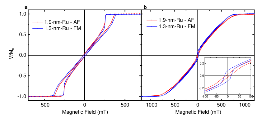
Since in our ML system, there are only a few Co layers with asymmetric Pt/Co/Ru interfaces (for the SAF , the ratio is ), we exclude any significant contribution of IDMI. Note that IDMI in Pt/Co/Ru and Ru/Co/Pt should have opposite signs, which diminishes the contribution of IDMI even further. Additionally, we compared magnetic hysteresis loops in samples with different Ru layer thicknesses as shown in the Extended Data Fig.3. When the Ru thickness is 1.3 nm, where the coupling is FM, the in-plane hysteresis loop exhibits similar characteristics to that of the Co/Pt ML with non-zero remanent magnetization. However, when we increase the Ru thickness to 1.9 nm, corresponding to the second maximum of the AF-coupling energy, the sample shows a vanishing remanent magnetization, similar to the SAF with 0.9 nm Ru. This provides clear evidence that the AF-like DW behaviour is caused by the AF interlayer exchange coupling and is not caused by any other interfacial effects.
To confirm the DW spin structure in the SAF system, we employed micromagnetic simulations using Mumax mumax and Excalibur excalibur . The details of the micromagnetic simulations are provided in the Methods section. The results of the numerical simulations for the SAF and Co/Pt systems are presented in Fig.1e, along with a magnification of the DWs between ”up” and ”down” domains in Fig.1f. Both systems exhibit an identical stripe-domain state, which is in line with the MFM data. On the other hand, the simulated DW spin structures of the two systems are very different. At the film surfaces both, SAF and Co/Pt systems display flux closing Néel-type DW components. In the center of the DWs, the Co/Pt system has a FM Bloch-type component which contributes an in-plane net magnetization to the DW. For the SAF system, the middle of the DW exhibits a subunit-wise in-plane AF ordering of magnetization with zero net magnetization. This explains the zero net magnetization observed in the in-plane major and minor loop magnetometry measurements in Fig. 1b, c.
Microscopic magnetic characterization of domain walls with Lorentz TEM
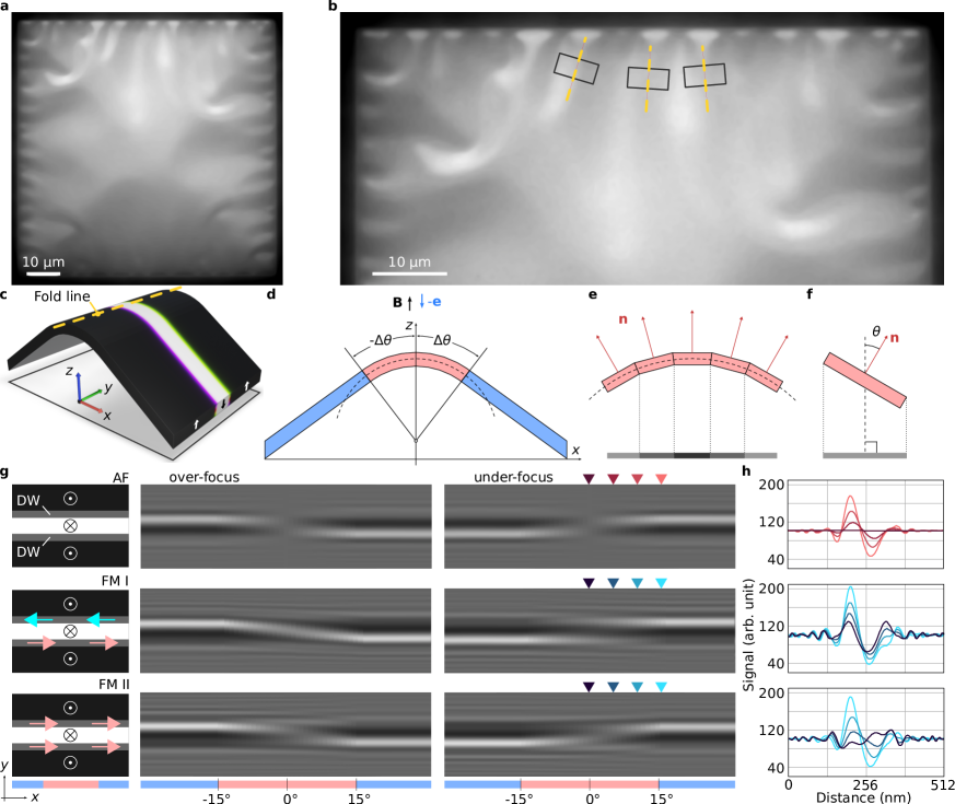
To reveal the presence of AF ordering not only by magnetization averaged measurements but also directly and spatially resolved within individual microscopic DWs, we designed a dedicated experiment using Lorentz transmission electron microscopy (LTEM). The LTEM measurements are typically conducted on respective sister samples that are deposited onto silicon nitride (Si3N4) membrane substrates. Due to internal mechanical strain between the Si3N4 and the metallic MLs these membrane samples usually exhibit buckled profiles with extensive folds and bends that form a characteristic stress pattern Ohring as shown in Fig. 2a, b. In many cases, this aspect is harmful to LTEM imaging, but we use it here specifically to our advantage. In particular, the imaging near the folded areas provides the opportunity to obtain unique information on the magnetic induction of the sample imaged at different angles with respect to the surface normal in one and the same image (Figure 2c-f). Figure 2g illustrates the expected LTEM contrast of an isolated stripe domain pathing across the fold line in the case of SAF and FM samples. When the electron beam is perpendicular to the membrane surface on top of a fold line, no Lorentz TEM contrast from the DWs in SAF with compensated magnetic moments is detectable (see top row in Figure 2g). That is because Lorentz TEM is sensitive only to the in-plane components of the magnetic induction. On the other hand, the projected in-plane magnetization of the DWs in the Co/Pt MLs should result in a pronounced contrast that is consistently present for all angles of the electron beam to the sample normal, also at the top of a fold line, where the beam enters parallel to the surface normal (see the second and third rows in Fig. 2g). Furthermore, the contrast of DWs in Co/Pt multilayers is expected to depend on the polarization direction of the adjacent DWs, as reported in Ref [Salikhov2021 ].
When a TEM membrane is folded up and down (Fig.2a and b) due to the buckling effect, and the electron beam is adjusted to be parallel to the -axis (Fig.2c and d), one obtains signals from the tilted ”up” and ”down” domain magnetizations where ever the local angle between the electron beam and domain magnetization deviates from zero. Since the tilt of the ML film is opposite for sections of the stripe domains on either side of the folding line (i.e., for opposite signs of the slope), their tilt-induced in-plane components of the magnetization have opposite directions. As a consequence the magnetic contrast of the DWs between the stripe domains becomes visible now and is expected to be inverted across the fold line along which the slope is zero. For zero slope there is no contrast from the perpendicular domain cores left, here along the fold lines only the DWs contribute to the Lorentz TEM contrast. Therefore, the inversion behavior of the magnetic contrast from the stripe domains is expected to be different close to the fold line, depending on the DW spin configuration. According to our simulations, in the case of an AF spin structure, the inversion occurs through zero contrast at the fold line, since the AF-DWs have zero net magnetization (see the first row in Fig.2g and h). However, the magnetic contrast from the FM-DWs in Co/Pt MLs contributes to the Lorentz TEM signal across the folding line, resulting in a smooth transition with non-zero contrast, as seen in the second and third rows in Fig.2g and h.
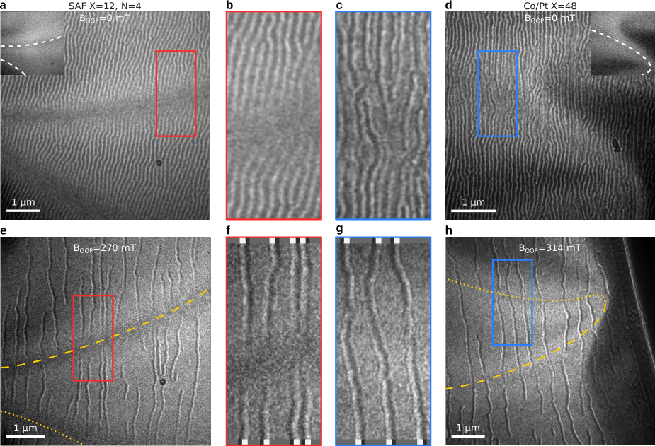
By selecting different folding line areas for LTEM imaging (some examples are marked with black rectangles in Fig.2b), we were able to obtain representative experimental images of aligned stripe domain states in the SAF and Co/Pt samples, as seen in Fig.3a and Fig.3d respectively. Figures 3b and 3c show a magnification of selected areas in Fig.3a,d. Even at large fields of view in Figs.3a,d it become apparent that there is a significant difference in the LTEM contrasts between the two FM-domain states. The SAF sample shows no contrast at the fold line (which can be identified from the in-focus TEM image in the inset of Fig.3a), while the Co/Pt sample provides magnetic contrast everywhere in the studied area, even at normal electron incidence. This is due to the overlap of signals from the stripe domains in the tilted region with the signal from the Bloch-type DWs.
To isolate the magnetic signal from a single stripe domain, we apply an external magnetic field of about 270 - 320 mT parallel to the electron beam direction. This causes the ”up”-domains to grow and the ”down”-domains to shrink. Figures 3e and 3h show the corresponding under focus LTEM images for SAF and Co/Pt samples. Now it becomes apparent that all stripe domains invert the magnetic contrast in the two tilted regions across the folding line, see also the magnified area images in Fig.3f and g. Unlike the Co/Pt sample, which shows a continuous transition due to an additional contribution from Bloch-type DWs, the SAF sample displays no magnetic contrast along the folding line (where the electron beam transmits the sample at normal incidence). The observed behavior of the PMA-SAF sample in the LTEM images confirms on a local level for individual stripe domains the coexistence of mixed FM domain core and AF DW magnetic spin structures and is consistent with our earlier interpretation based on the magnetization averaged minor loop studies.
Extension from parallel stripe to dense bubble domain states
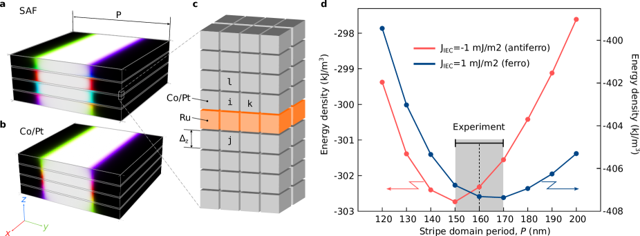
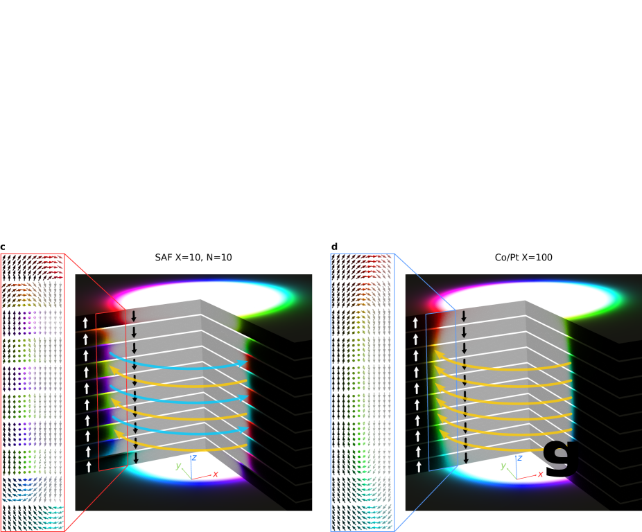
Finally, we extend our study to FM bubble domains in SAFs that exhibit AF ordering within their DWs. By using the approach outlined in our previous study Salikhov2022 , we stabilized dense bubble states in the SAF sample as well as in Co/Pt sample with = 100. Corresponding MFM images for the SAF and Co/Pt samples are presented in the respective insets in Fig.4a and b. Without altering the topography of the bubble state we then measured minor hysteresis loop series, similar to those previously performed on the aligned stripe-domain state (see Extended Data Fig.2c,d). The results of these measurements for bubble states can be found in Fig.4a for the SAF sample and Fig.4b for the Co/Pt reference sample. Again, the Co/Pt sample shows irreversible switching of the DWs from one type-II state to another with opposite polarisation via type-I states with different chiralities Slonczewski1976 ; Patek1993 . The magnetization of the DWs in the SAF sample shows almost fully reversible behavior, akin to antiferromagnets with a linear dependence on the applied field. This behavior is similar to what we previously observed in the aligned stripe-domain state of the same SAF sample with (see Extended Data Fig.2c), indicating that the magnetic bubbles in the PMA-SAF are of type-I, with alternating chirality across the Ru-layers. The latter finding agrees with the results of micromagnetic simulations for the SAF sample in Fig.4c, where we also observe the spontaneous formation of alternating chirality in adjacent AF sub-units within the domains walls of the bubble domains.
As seen in Fig.4c, the domain walls at the topmost and bottommost layers are shifted with respect to the domain walls in the internal layers. This phenomenon, known as the exchange shift of domain walls, has been studied in the literature earlier Kiselev07 ; Kiselev08 . The exchange shift causes the magnetization in adjacent layers to be ordered antiferromagnetically with respect to each other. In the case of antiferromagnetic IEC, such ordering provides an extra energy gain in the narrow region between the shifted domain walls.
Conclusions
Our study reveals the presence of mixed FM/AF textures in SAF MLs with weak RKKY-type interlayer exchange coupling, which is overcome by the strong demagnetization fields within the perpendicular domain cores, but still prevails within the Bloch-type in-plane magnetized domain walls. As a result, we obtain so far unexplored types of mixed FM/AF textures featuring FM perpendicular stripe and bubble domains separated by AF Bloch-type DWs. This domain wall structure offers unique possibilities for a wide range of functionalities in PMA-SAFs. Potential applications include using the DWs of aligned stripe domains for nonreciprocal spin wave channeling Banerjee2017 ; Gruszecki2019 ; Petti2022 ; Lei2022 and bubble states with alternating chirality for race track-type applications Fert2017 ; Nagaosa2013 ; Fattouhi2021 . Also, recent research has shown that AF-coupled MLs can be reversibly switched between FM and AF states via voltage gating, which could be potentially extended to control the DW state to be either FM or AF in such mixed FM/AF bubble domain arrays Kossak2023 . Finally, also neuromorphic type of computing applications based on magnetic domain systems and textures Song2020 ; Bourianoff2018 ; Kurenkov2020 ; Li2021 could benefit from another degree of freedom within the domain wall structure. Overall our findings extend the perspective for domain wall structure design and pioneer a so far unexplored pathway towards combining FM and AF order in nanoscale domain structures.
Methods
Sample fabrication. The MLs were fabricated using dc magnetron sputter deposition at 0.4 Pa ( mbar) Ar atmosphere in an ultrahigh vacuum ATC 2200 system from AJA International Inc. Si wafers with 100-nm-thick thermally oxidized (SiO2) layer as well as Si3N4 membranes were used as substrates. Prior to the ML deposition, a 1.5 nm Ta layer was deposited for adhesion purposes. A subsequent Pt layer (20 nm on SiO2 and 5 nm on Si3N4) serves as a seed in order to obtain a preferred Co/Pt (0001)/(111)-texture, which supports better growth and larger PMA Fallarino . The samples were finally capped by a 2 nm Pt layer to avoid surface oxidation. Structural characterization of the sample architecture has been performed via x-ray reflectivity using a Cu radiation source diffractometer (Rigaku SmartLab XG). Exemplary reflectivity profiles are displayed for the SAF versus Co/Pt sample in Extended Data Fig.1a,b and allow a clear distinction between the double period ML SAF versus the single period Co/Pt ML.
Magnetic measurements were performed using a commercial Microsense EZ7 vibrating sample magnetometer (VSM), equipped with an electromagnet, which delivers up to 1.8 T magnetic field. The saturation magnetization of all samples was measured using the VSM and calculated to be = 0.8 ± 0.1 MA/m for both SAF and Co/Pt systems. The PMA constant is determined from the in-plane saturation field of a Co/Pt sample with = 12. Accordingly, by varying the Co thickness and keeping the Pt thickness constant (0.7 nm) we obtained the largest PMA within our sample set to be of about MJ/m3 at the Co thickness of 0.44 nm. The AF exchange constant in SAFs was derived from the calibration {[Co(0.44 nm)/Pt(0.7 nm)]X-1/Co(0.44 nm)/Ru(0.9 nm)}N-1[Co(0.44 nm)/Pt(0.7 nm)]X ML with , which shows a rectangular shape of the field-dependent magnetization in the out-of-plane geometry. The interlayer exchange coupling constant mJ/m2 was calculated according to the equation , where is the thickness of a Co/Pt = 5 block, and is the averaged spin-flop field. Having all parameters (, PMA, and ) for SAF MLs fixed, we varied the and until the FM state in SAFs is reached according to the diagram in Ref. Hellwig2007 .
The aligned stripe domain states in all the samples were prepared using a specific ac-demagnetization (ACD) routine, namely by alternating the magnetic field direction parallel to the sample surface with subsequent reduction of the field amplitude from 1.8 T down to 2 mT in steps.
Imaging techniques Magnetic domain imaging was performed using a magnetic force Bruker Dimension Icon microscope. The LTEM studies were performed with a JEOL Jem F-200C - transmission electron microscope, operated at 200 kV acceleration voltage, in the Lorentz (Fresnel) mode. All images were recorded at room temperature.
Micromagnetic simulations. The total micromagnetic energy of the system includes the following terms: Heisenberg exchange, interlayer exchange coupling, uniaxial anisotropy, Zeeman energy, and the energy of the demagnetizing fields. In a multilayer system, the exchange coupling between Co layers across the Pt inter-layer is weaker than the direct exchange within the Co layer. We assume that the plane of the multilayer is in -plane. Thereby the Heisenberg exchange interaction energy density within the Co/Pt stack can be approximated as follows Salikhov2021
| (1) |
where the summation runs over component of the magnetization unit vector field, . The constant is the exchange stiffness in the plane of the film, while the unitless constant defines the strength of the exchange coupling between Co layers across the Pt layers. In our simulations, we use pJ/m and estimated for [(Co(0.44 nm)/Pt(0.7 nm)]X multilayers in Ref. Salikhov2021 .
The interlayer exchange coupling of Co/Pt stacks across Ru interlayer is defined by the following surface energy density expression:
| (2) |
where and are the magnetization at the interface, and is the coupling constant given in units of J/m2. For ferromagnetic interlayer exchange coupling, and for antferromagnetic coupling . In practice, on a discrete lattice of cuboids, the energy term (2) is implemented as follows,
| (3) |
where and are the magnetization in the cuboids separated by nonmagnetic spacer as illustrated in Extended Data Fig. 4c, and is the height of the cuboids along -axis. To implement this interaction in Mumax, we used the option of custom effective fields. For details of implementation, see the Mumax script file in Supplementary Data. In our simulations, we use the experimentally estimated value of antiferromagnetic interlayer exchange coupling, mJ/m2 corresponding to 0.9 - nm - thick Ru layer. We also use experimentally measured values of saturation magnetization kA/m and uniaxial anisotropy MJ/m3. For the calculation of the isolated stripe domain and equilibrium period of stripe domains at zero applied magnetic field ( Extended Data Fig. 4d) in , multilayer, we use a mesh density of cuboids. The thickness of the cuboids along the -axis was set to 1 nm, while the lateral size of the cuboid may vary in the range between 1 nm and 2 nm. For the simulation presented in Fig. 1e-f, we use a domain of square shape in the -plane with a size of nm (twice the stripe-domain period), while for simulations in Fig. 2, we use domain with nm.
Simulations of Lorentz TEM images. To calculate the Lorentz TEM images in the case of an electron beam perpendicular to the film plane, we follow a well-established approach based on phase object approximation MarcDe_Graef , in detail described in Ref. Zheng_21 . When the electron beam has an arbitrary tilt angle to the plane of the sample, the magnetic contribution to the phase shift can be calculated as Lichte_08
| (4) |
where is the unit vector along the incident electron beam, is an elementary (positive) charge and is Planck’s constant, is the magnetic vector potential induced by the sample magnetization, and and are the coordinates in the plane orthogonal to the beam direction.
Acknowledgments
The authors are grateful to Thomas Naumann and Jakob Heinze for experimental and technical support. NSK thanks Filipp Rybakov for the fruitful discussions and for providing access to the Excalibur code.
This work was supported by Deutsche Forschungsgemeinschaft through project 514946929 (Gemischt-ferromagnetisch-antiferromagnetische Hybridphase von Streifen- und ”Bubble”-Domänenstrukturen für magnonische Kristall und ”Race-Track”-Anwendungen) and within the priority program SPP 2137 through project 403503416.
References
- (1) Woo, S., Litzius, K., Krüger, B. et al., Observation of room-temperature magnetic skyrmions and their current-driven dynamics in ultrathin metallic ferromagnets. Nat. Mater. 15, 501 (2016).
- (2) Fert, A., Reyren, N. & Cros, V. Magnetic skyrmions: advances in physics and potential applications. Nat. Rev. Mater. 2, 17031 (2017).
- (3) Nagaosa, N. & Tokura, Z. Topological properties and dynamics of magnetic skyrmions. Nat. Nanotechnol. 8, 899 (2013).
- (4) Jiang, W., Zhang, X., Yu, G., Zhang, W. et al., Direct observation of the skyrmion Hall effect. Nat. Phys. 13, 162-169 (2017).
- (5) Litzius, K., Lemesh, I., Krüger, B. et al., Skyrmion Hall effect revealed by direct time-resolved X-ray microscopy. Nat. Phys. 13, 170-175 (2017).
- (6) Legrand, W., Chauleau, J.-Y., Maccariello, D. et al., Hybrid chiral domain walls and skyrmions in magnetic multilayers. Sci. Adv. 4, eaat0415 (2018).
- (7) Lucassen, J., Meijer, M.J., Kurnosikov, O. et al., Tuning magnetic chirality by dipolar interactions. Phys. Rev. Lett. 123, 157201 (2019).
- (8) Tomasello, R., Martinez, E., Zivieri, R., Torres, L., Carpentieri, M. & Finocchio, G. A strategy for the design of skyrmion racetrack memories. Sci. Rep. 4, 6784 (2014).
- (9) Malozemoff, A.P.& Slonczewski, J.C. Magnetic domain walls in bubble materials. Academic Press, New York, 1979.
- (10) Hubert, A. & Schäfer, R. Magnetic Domains. Springer, Berlin, 2009.
- (11) Moreau-Luchaire, C., Moutafis, C., Reyren, N. et al., Additive interfacial chiral interaction in multilayers for stabilization of small individual skyrmions at room temperature. Nat. Nanotechnol. 11, 444 (2016).
- (12) Pollard, S.D., Garlow, J.A., Yu, J. et al., Observation of stable Néel skyrmions in cobalt/palladium multilayers with Lorentz transmission electron microscopy. Nat. Commun. 8, 14761 (2017).
- (13) Parkin, S.S.P., More, N., & Roche, K.P. Oscillations in exchange coupling and magnetoresistance in metallic superlattice structures: Co/Ru, Co/Cr, and Fe/Cr. Phys. Rev. Lett. 64, 2304 (1990).
- (14) Stiles, M.D. Interlayer exchange coupling. J. Magn. Magn. Mater. 200, 322 (1999).
- (15) Yang, S.-H., Ryu, K.-S., & Parkin, S. Domain-wall velocities of up to 750 m/s driven by exchange-coupling torque in synthetic antiferromagnets. Nat. Nanotechnol. 10, 221 (2015).
- (16) Dohi, T., DuttaGupta, S., Fukami, S., & Ohno H. Formation and current-induced motion of synthetic antiferromagnetic skyrmion bubbles. Nat. Commun. 10, 5153 (2019).
- (17) Legrand, W., Maccariello, D., Ajejas, F. et al., Room-temperature stabilization of antiferromagnetic skyrmions in synthetic antiferromagnets. Nat. Mater. 19, 34 (2020).
- (18) Chen, R., Gao, Y., Zhang, R. et al., Realization of isolated and high-density skyrmions at room temperature in uncompensated synthetic antiferromagnets. Nano Lett. 20, 3299–3305 (2020).
- (19) Juge, R., Sisodia, N., Larrañaga, J. U. et al., Skyrmions in synthetic antiferromagnets and their nucleation via electrical current and ultra-fast laser illumination. Nat. Commun. 13, 4807 (2022).
- (20) Chen, R., Cui, Q., Han, L. et al., Controllable generation of antiferromagnetic skyrmions in synthetic antiferromagnets with thermal effect. Adv. Funct. Mater. 32, 2111906 (2022).
- (21) Duine, R.A., Lee, K.-J., Parkin, S.S.P., & Stiles, M.D. Synthetic antiferromagnetic spintronics. Nat. Phys. 14, 217 (2018).
- (22) Fattouhi, M., Mak, K.Y., Zhou, Y. et al., Logic gates based on synthetic antiferromagnetic bilayer skyrmions. Phys. Rev. Appl. 16, 014040 (2021).
- (23) Song, K.M., Jeong, J.-S., Pan, B. et al., Skyrmion-based artificial synapses for neuromorphic computing. Nat. Electron. 3, 148 (2020).
- (24) Hellwig, O., Kirk, T.L., Kortright, J.B., Berger, A. & Fullerton E.E. A new phase diagram for layered antiferromagnetic films. Nat. Materials 2, 112 (2003).
- (25) Hellwig, O., Berger, A. & Fullerton E.E. Domain walls in antiferromagnetically coupled multilayer films Phys. Rev. Lett. 91, 197203 (2003).
- (26) Hellwig, O., Berger, A., Kortright, J.B., & Fullerton E.E. Domain structure and magnetization reversal of antiferromagnetically coupled perpendicular anisotropy films. J. Magn. Magn. Mater. 319, 13 (2007).
- (27) Bran, C., Butenko, A.B., Kiselev, N.S. et al., Evolution of stripe and bubble domains in antiferromagnetically coupled [(Co/Pt)8/Co/Ru]18 multilayers. magnetic anisotropy at ambient conditions. Phys. Rev. B 79, 024430 (2009).
- (28) Hauet, T. Günther, C.M., Havorka, O. et al., Field driven ferromagnetic phase nucleation and propagation in antiferromagnetically coupled multilayer films with perpendicular anisotropy. Appl. Phys. Lett. 93, 042505 (2008).
- (29) Hellwig, O., Günther, C.M., Radu, F., Menzel, A., Schlotter, W.F., Lüning, J. & Eisebitt, S. Ferrimagnetic stripe domain formation in antiferromagnetically-coupled Co/Pt–Co/Ni–Co/Pt multilayers studied via soft x-ray techniques. Appl. Phys. Lett. 98, 172503 (2011).
- (30) Salikhov, R., Samad, F., Böhm, B. et al., Control of stripe-domain-wall magnetization in multilayers featuring perpendicular magnetic anisotropy. Phys. Rev. Appl. 16, 034016 (2021).
- (31) Vansteenkiste, A., Leliaert, J., Dvornik, M., Helsen, M., Garcia-Sanchez, F., & Van Waeyenberge, B. The design and verification of MuMax3 AIP Advances 4, 10 (2014).
- (32) F. N. Rybakov and E. Babaev, Excalibur software, http://quantumandclassical.com/excalibur/.
- (33) Ohring, M. The Material Science of Thin Films. Academic Press, New York, 1992.
- (34) Salikhov, R., Samad, F., Arekapudi, S.S.P.K. et al., Control and tunability of magnetic bubble states in multilayers with strong perpendicular magnetic anisotropy at ambient conditions. Phys. Rev. B 106, 054404 (2022).
- (35) Dekker, P., & Slonczewski, J.C. Switching of magnetic bubble states. Appl. Phys. Lett. 29, 753 (1976).
- (36) Patek, K., Gemperle, R., Murtinova, L., & Kaczer, J. Magnetization reversal and Bloch lines in bubble domain walls. J. Magn. Magn. Mater. 123, 223-229 (1993).
- (37) Kiselev, N. S., Dragunov, I. E., Rößler, U. K., & Bogdanov, A. N. Exchange shift of stripe domains in antiferromagnetically coupled multilayers. Appl. Phys. Lett. 91, 132507 (2007).
- (38) Kiselev, I. E., Rößler, U. K., Bogdanov, A. N., Hellwig, O. Topological defects in antiferromagnetically coupled multilayers with perpendicular anisotropy. Appl. Phys. Lett. 93, 162502 (2008).
- (39) Banerjee, Ch., Gruszecki, P., Klos, J.W., Hellwig, O., Krawczyk, M., & Barman, A. Magnonic band structure in a Co/Pd stripe domain system investigated by Brillouin light scattering and micromagnetic simulations. Phys. Rev. B 96, 024421 (2017).
- (40) Gruszecki, P., Banerjee, Ch., Mruczkiewicz, M., Hellwig, O., Barman, A., & Krawczyk, M. The influence of the internal domain wall structure on spin wave band structure in periodic magnetic stripe domain patterns. Solid State Physics 70, 79-132 (2019).
- (41) Petti, D., Tacchi, S., & Albisetti, E. Review on magnonics with engineered spin textures. J. Phys. D: Appl. Phys. 55 293003 (2022).
- (42) Qiu, L., & Shen, K. Tunable spin-wave nonreciprocity in synthetic antiferromagnetic domain walls. Phys. Rev. B 105, 094436 (2022).
- (43) Kossak, A.E., Huang, M., Reddy, P., Wolf, D., & Beach, G.S.D. Voltage control of magnetic order in RKKY coupled multilayers. Sci. Adv. 9, eadd054 (2023).
- (44) Bourianoff, G., Pinna, D., Sitte, M., & Everschor-Sitte, K. Potential implementation of reservoir computing models based on magnetic skyrmions. AIP Advances 8, 055602 (2018).
- (45) Kurenkov, A., Fukami, S., & Ohno, H. Neuromorphic computing with antiferromagnetic spintronics. J. Appl. Phys. 128, 010902 (2020).
- (46) Li, S., Kang, W., Zhang, X. et al., Magnetic skyrmions for unconventional computing. Materials Horizons 8, 854-868 (2021).
- (47) Fallarino, L., Oelschlägel, A., Arregi, J.A. et al., Control of domain structure and magnetization reversal in thick Co/Pt multilayers. Phys. Rev. B 99, 024431 (2019).
- (48) De Graef, M. Lorentz microscopy: Theoretical basis and image simulations. In: Experimental Methods in the Physical Sciences 36, 27 (2001).
- (49) Zheng, F. et al. Magnetic skyrmion braids. Nat. Commun. 12, 5316 (2021).
- (50) Lichte, H. & Lehmann, M. Electron holography – basics and applications. Rep. Prog. Phys. 70, 016102 (2008).