Two-qubit atomic gates: Spatio-temporal control of Rydberg interaction
Abstract
By controlling the temporal and spatial features of light, we propose a novel protocol to prepare two-qubit entangling gates on atoms trapped at close distance, which could potentially speed up the operation of the gate from the sub-micro to the nanosecond scale. The protocol is robust to variations in the pulse areas and the position of the atoms, by virtue of the coherent properties of a dark state, which is used to drive the population through Rydberg states. From the time-domain perspective, the protocol generalizes the one proposed by Jaksch and coworkers [Jaksch et al., Phys. Rev. Lett., 2000, 85, 2208], with three pulses that operate symmetrically in time, but with different pulse areas. From the spatial-domain perspective, it uses structured light. We analyze the map of the gate fidelity, which forms rotated and distorted lattices in the solution space. Finally, we study the effect of an additional qubit to the gate performance and propose generalizations that operate with multi-pulse sequences.
I Introduction
Due to their excellent optical addressability, [1, 2, 3, 4, 5] rich many-body physics,[6, 7, 8, 9, 10, 11, 12] and long decoherence times,[13] neutral atoms excited in Rydberg states have been used as vectors for different quantum technologies, including entanglement preparation, [14, 15, 16, 17, 18, 19, 20, 21] creation of photonic entanglement, [22] quantum simulators, [23, 24, 25, 26] and quantum computation.[27, 13, 28, 19, 29, 30, 31, 32, 33, 34]
A key step involves trapping the atoms at low temperature in magneto-optical traps (MOT). Homogeneous magnetic fields working on the MOT split the degeneracy of the hyperfine ground states of the atoms, allowing to encode and address separately the qubit states by optical fields through intermediate states or using microwave fields.[35, 36, 37] Currently, it is possible to create splittings of the order of GHz[14] that in principle, allow to drive the population from the state independently of the state in the nanosecond regime.
On the other hand, due to the strong dipole-dipole interaction of Rydberg states, [38, 39] the energy of a double excitation of Rydberg states is larger than twice the energy of each atom in a Rydberg state. For weak enough pulses (or close enough atoms) this extra energy is also larger than the Rabi frequency driving the transition, and the state cannot be populated. This defines a maximum distance, called the Rydberg blockade radius, , within which the well-known C-PHASE gate protocol was proposed by Jaksch et al. [27]. The three-pulse sequence protocol consists of a -pulse acting on the first qubit, followed by a -pulse acting on the second qubit, and a -pulse again acting on the first qubit. The pulse frequencies are tuned to excite the chosen Rydberg state, from the qubit state (alternatively, from the state) so the other qubit state is decoupled. Then if the system is initially in the state, the first pulse moves the amplitude to , the second does nothing and the third moves the amplitude to . If the system starts in , the first pulse acts as before, driving the amplitude to , the second does nothing and the third induces the transition to . When the system is in the first pulse does nothing, the second drives the amplitude to and the third does nothing. Finally, the lasers cannot induce any transition from the state. In the following, we will refer to this set of operations as the Jaksch protocol (JP).
There have been several proposals to extend the JP mechanism using more robust adiabatic excitation schemes[40, 41, 42] adding alternative processes to the dipole blockade through dark states,[43] or addressing multi-qubit gate generalizations.[33, 34, 44, 45] Some of these ideas extend well known optical control adiabatic strategies [46, 47, 48, 49] for dynamics with target states conditioned on the initial state. [50, 51, 52, 53] One disadvantage of these schemes is the need to work with long pulses, in the microsecond regime. In the JP scheme, this is needed to operate with independent qubits, forcing interatomic distances of the order of m, with Rydberg-Rydberg interactions, , of a few MHz. The time-scale gap in and offers an opportunity to speed the gates typically by two orders of magnitude, by using denser arrays of atoms, therefore boosting the dipole blockade such that . Although the physics of Rydberg states is rich and several unwanted physical processes may be involved in working in denser media, [54, 17, 55, 56, 57, 58, 59, 60] it is important to estimate if the JP can operate under these conditions or if one can design other robust protocols for the gates with non-independent qubits.
One way to extend the JP to more compact arrangements of atoms is to implement control not only in time (encoded in the pulse sequence), but also in space (encoded as geometrical parameters) taking into account the strength of the light-matter interaction at the exact qubit locations. In the simplest arrangements, the spatial control might just involve specific focusing of each laser light at different points of the lattice formed by the atoms, not just necessarily at the site that the atom occupies, using various TEM modes of light.[61]
Here we examine the potential advantages of using so-called structured light for the entangling gate implementation. Recent advances in the control of spatial properties of light have been used to create topological electromagnetic effects, as well as almost arbitrary complex geometrical patterns that can be complemented with pulse shaping techniques.[62, 63, 5] For instance, a superposition of TEM00 and TEM01 or TEM10 can be used to create nodes and phase relations between the peak values of the fields at nearby locations. In addition to the space-dependent intensities, such hybrid modes (see the sketch in Fig.1) may have different phases at different positions of the atoms. The idea is to use a symmetrical protocol where the first pulse and its copy, focusing on the first qubit, are applied before and after a second pulse acts mostly on the second qubit. We prove that a particular relation in the spatial features of the pulses confers special robustness to the gate implementation, giving raise to the Symmetric Orthogonal Protocol or SOP that is proposed in this work. By incorporating the basic features of spatio-temporally controlled pulses as parameters in the Hamiltonian, we design simple models to estimate the fidelities for two- and three-qubit systems, implementing the C-PHASE type gate. The complexity of the system increases with the number of parameters, but what can be seen as a drawback, may be seen as an opportunity to find novel ways to control the system using optimization techniques.
Our study is a first demonstration of quantum control application[64, 65, 66] to design quantum gates addressing both the spatial and temporal features of the laser fields. Using simplified models at zero temperature and without noise, we show that the spatio-temporal control of the fields acting locally on each qubit can be used to achieve robust and efficient implementations of fast entangling gates. In fact, this theoretical setup offers many more practical implementations to control gates and prepare entanglement, which will be addressed in the future. The speed of the designed gates justifies some our assumptions, like neglecting decoherence, dephasing, and most mechanisms that might lead to fidelity losses. However, more detailed studies considering the effect of other states in the system, the presence of Stark shifts, noise in the pulses, and the motion of the atoms, are required to assess the practical implementation of the SOP.
II Gate performance for non-separated qubits: Analysis
The computational basis of a two-qubit in our system is composed of , , and states. Together with the Rydberg ancillary states: , , , , form the basis where we will follow the evolution of the system, as we assume that the state cannot be accessed by strong Rydberg blockade. We assume that the distance between atoms is shorter than the waist of the laser beams. As a first approximation to model the local effect of the field on each of the qubits, we define geometrical factors, and , so the spatially and temporally dependent interaction of the laser at qubit () is determined by the Rabi frequencies . The geometrical factors can be partially incorporated in the Franck-Condon factor so we can assume, without loss of generality, that and are normalized to unity (). Using hybrid modes of light (structured light) one can control and in a wide range of values, including negative factors.
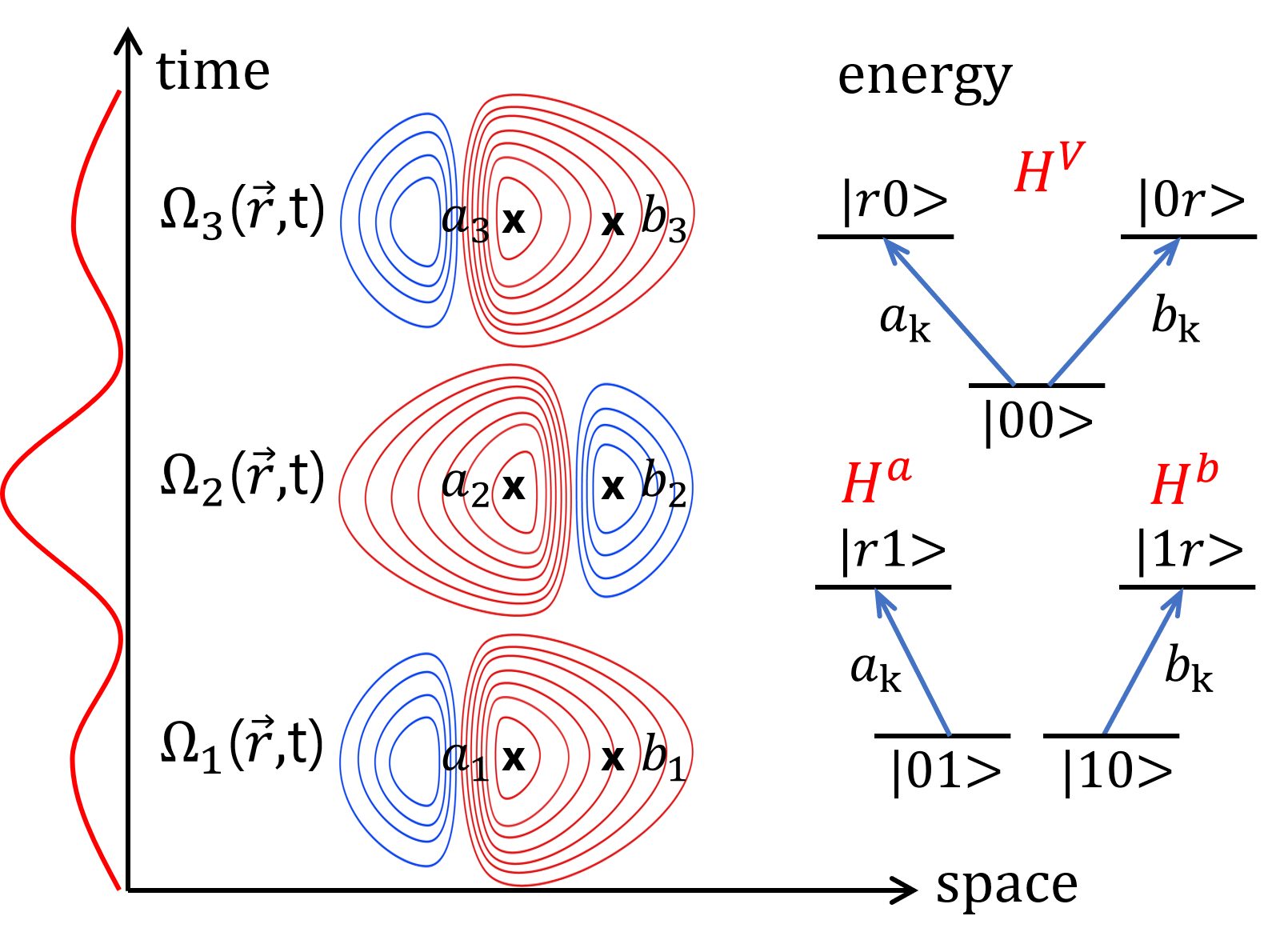
Using a pulse sequence of non-overlapping pulses , in resonance between the state of the qubit and the chosen Rydberg state , the Hamiltonian is block-diagonal, , where is the Hamiltonian of a -level system in configuration, acting in the subspace of states, and are two-level Hamiltonians acting in the subspace of and respectively. Finally, is a zero Hamiltonian acting on the state , decoupled from any field. The energy diagrams of the subsystems are shown in Fig1.
The time-evolution operator of any of these Hamiltonians can be solved analytically through their time-independent dressed states, that have zero non-adiabatic couplings.[67, 68, 69] For reference, we include here the analytical form of the time-evolution operators at the end of the pulses. For ,
| (1) |
where the mixing angle
is half the pulse area. Interestingly, supports a dark state, . This is a dressed state of zero energy, which is uncoupled to the ground state, , that is, cannot decay nor be excited by the field. On the other hand, the time-evolution operator that affects the initial states and , is
| (2) |
where .
Effect on
Let us predict the effect of the JP on the partially distinguishable qubits. Excitation from with a -pulse prepares the entangled state . Because there is population in both qubits and acts on both, the second pulse can induce transitions from , breaking the mechanism of the JP. If we want to remain undisturbed, we need to be the dark state of , , for which and . Then the third pulse can be another copy of the first pulse, transforming back into .
To generalize the result we define structural vectors, which are normalized two-component vectors formed by the geometrical factors, that characterize the spatial properties of the protocol. Success in the gate performance (starting in ) implies that the first diagonal element of the full propagator, . Working out the matrix multiplication we obtain
| (3) |
where we have used the compact notation , . This formula is valid in general for a -pulse sequence on arrays of qubits, where becomes a -dimensional vector. The condition that (the dark state of ) is that is orthogonal to both and . In symmetric protocols, with and , one obtains the equation that defines the behavior under the SOP,
| (4) |
For -qubit systems, the normalization and orthogonality of the structural vectors implies that there is only one free parameter, , that measures the overlap of the field on both qubits and as such, indirectly measures the proximity of the atoms in the trap.
If , as in the JP, regardless of and for any value of . In addition, Eq.(4) guarantees a remarkable robustness to variations in the pulse areas. Making , and , one can easily obtain
| (5) |
Any error in the pulse areas will only add a quartic error in ().
Effect on and
To evaluate the gate performance when the two-qubit system is initiated in or we use Eq.(2). In a symmetrical sequence, the final state will be ()
| (6) |
In Jaksch protocol, (, ), for independent qubits, as only one component, or , exist. But for orthogonal geometrical factors (),
| (7) |
inducing quadratic deviations in that lower the fidelity of the gate.
A compromise must be made in the choice of the pulse areas. Because does not depend on the geometrical factors (nor on ), the pulse parameters should be adjusted mainly due to their effect on and . which require “rotating” the pulse areas. From Eq.(6), for any pulse area in the SOP, we obtain
| (8) | |||
| (9) |
where we use even and odd pulse areas. We can write Eqs.(8,9) in terms of new mixed pulse areas , , where
| (10) |
such that , , as in the JP, but for the new mixed pulse areas. Although will affect the overall fidelity, we observe that the effect of using orthogonal geometrical vectors is to rotate clockwise by an angle , the pulse areas that will give maximal but not perfect fidelities.
III Gate performance for non-separated qubits: Numerics
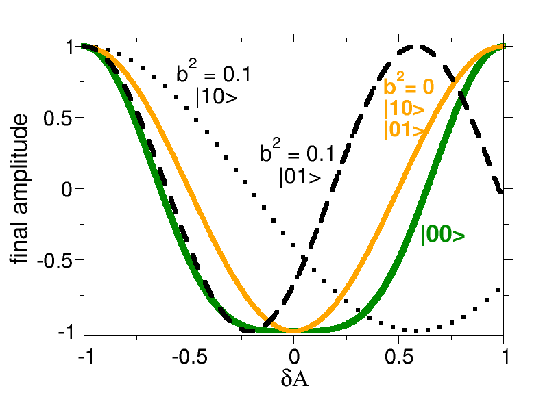
As discussed in the previous section, the orthogonality of the geometrical factors assures that population passage in the subsystem comprising the , and states, goes through a dark state. It is so robust that errors in the pulse areas only imply quartic deviations in regardless of the value of , that is, of the proximity of the qubits. This is shown In Fig.2 (solid line), where are computed for the different subsystems as a function of variations in pulses areas from the JP, assuming . On the other hand, increases quadratically around the minima (dashed black lines in Fig.2) and become disaligned for and as increases. Thus, the desired value of may fall outside of the flat band that characterizes the behavior of around its minima, disrupting the gate’s efficiency.
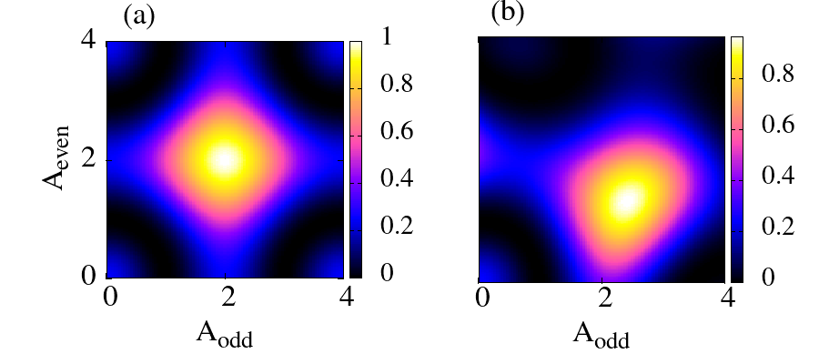
To optimize the gate one needs to change the pulse areas in specific directions. The smallest optimal pulse areas that maximize the fidelity are shown in Fig.3, for . To avoid a distortion in the map of solutions (henceforth fidelity map) we represent the map as a function on the area acting on each qubit, and , rather than and . We obtain a maximum fidelity of displaced to larger areas in and smaller areas in . The overall pulse area, , is however smaller than in the JP (). On the other hand, the overall robustness of the gate, measured as the area occupied by the maximum in the space of solutions, is practically the same.
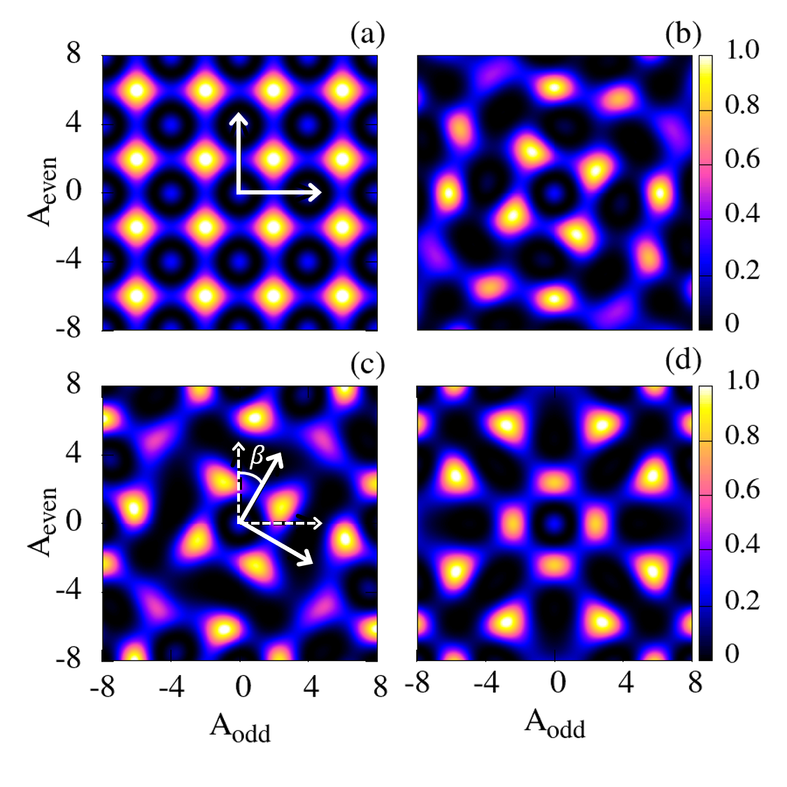
But this is only the minimal pulse area implementation. In the JP, other solutions are possible modulo area in the areas of the first and third pulses, and , and modulo in . Hence the family of protocols with symmetric pulses () satisfying and , where are integers, give perfect fidelity in the absence of noise or perturbations. While in the JP all the different protocols give the same fidelity, this is not the case for the SOP. Exploring solutions for larger pulse areas, better fidelities () are found, as shown in Fig.4.
The fidelity map for the JP is a regular lattice with spacings . In the SOP, the lattice is rotated with respect to the JP, with a rotation angle of , in agreement with Eq.(10). There are some distortions as increases, regaining a perfect, but different, symmetrical pattern as one reaches (). All maps for different have approximately the same number of maxima, separated a minimum distance of , so the density of solutions is conserved. However, except for the case, not all the fidelities at the maxima reach unity. Typically, larger areas are needed to find better solutions, e.g. , for a total area of and a peak fidelity of for . On the other hand, the minimal pulse area at which the first maxima appears decreases with , and for one observes using only, or and , for a total area of only .
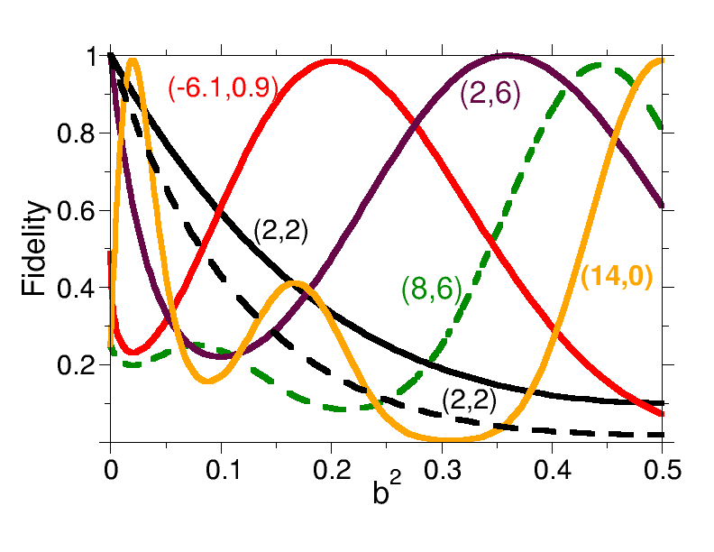
Instead of plotting how the fidelity map varies as a function of the pulse areas for fixed geometrical factors, we can fix the areas and vary . This is done in Fig.5. Only a few possible choices for the pulse areas are shown. The black line shows how the fidelity falls with the JP parameters, , , as increases. In terms of and we classify this protocol with a couple of numbers in units of . Other implementations of the JP scheme without minimal pulse areas, as , decay faster than the because of the larger accumulated pulse area, but surprisingly recover and work perfectly at different values of . Protocols that do not belong to the JP, as , where is not of the form , fail at but also provide high fidelities at certain values of .
Although natural multiples of for the pulse areas usually work relatively well, the ratios between the areas do not need to be natural numbers. The number of solutions is dense. For instance, taking into account the rotation of the optimal pulse areas depending on , we show how the fidelity changes for the protocol , which maximizes the fidelity at [see Fig.4(c)]. More surprisingly, one also finds solutions that do not require the three-pulse strategy, like in which the second pulse does not participate, but nevertheless one achieves high fidelities at low and large . These protocols are related to approximate solutions of Diophantine equations, where the gate mechanism does not rely on the dark state. They will be explored elsewhere.
The curves in Fig.5 show that the fidelities decay following a quadratic behavior when the geometrical factors depart from the optimal values, as expected. However, the decay is often slower at larger . (And the effect is even more noticeable if is plotted against , instead of .) Interestingly, the SOP guarantees a slower decay in the presence of the other qubit. Compare the black line with the black dashed line. In the black dashed line we start in the JP conditions and show what happens when the atoms approach (the qubits are no longer independent) but we do not use structured light. Then instead of . In solid black line we use the SOP. As long as the displacement of the atoms preserves the orthogonality of the structural vectors, the decay in the fidelity of the SOP is clearly slower.
IV Three-qubit systems
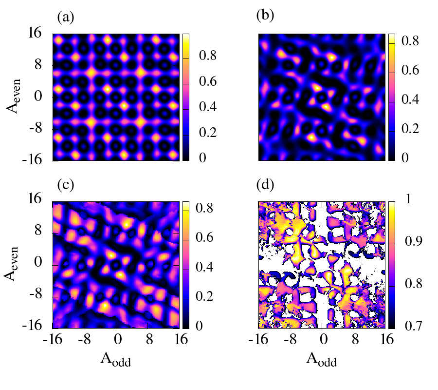
The protocol proposed in this work implies the use of denser arrays of trapped atoms. It is then important to analyze its robustness to the presence of other qubits not involved in the two-qubit gate. In this section, we check the efficiency of the SOP to prepare the gate , which is the C-PHASE gate acting on qubits and in the presence of qubit . This gate must operate exactly as with two qubits, regardless of the state of the third qubit, hence the diagonal of the matrix has the signature when the basis is ordered as . The theoretical treatment follows closely the analysis in Section.2 and the main equations (4), (6) remain valid by adding a third component, , which gives the geometrical factor on qubit , to the structure vector .
For independent qubits, as in the JP, the result is the same as for two qubits, see Fig.4(a). However, if the third qubit is close to the other two ( for all pulses), even if the second and first qubits are sufficiently apart (), the fidelity already decreases as shown in Fig.6(a). The lattice of solutions looks like in the two-qubit system, but some local maxima can be rather smaller than one, although high fidelity solutions still exist.
On the other hand, if one starts with nearby qubits and and implements the SOP, is the presence of qubit more disrupting? The answer is in Fig.6(b), where we assumed that for all pulses, and we applied the SOP to the remaining qubits forcing orthogonality and symmetric conditions.
As in the -qubit case, the fidelity map is rotated by approximately the same angle as before, with a slight shift due to . But the highest fidelities are now clearly smaller than one (), making the protocol less useful.
What if the parameters are optimized? Can one control the position of qubit (or the spatial profile of the laser located in this qubit) such that the fidelity increases, for fixed values of the other geometrical parameters? Fig.6(c) shows that the third qubit cannot be used to improve the fidelity of the gate. Here we project at every value of the best fidelity obtained by optimizing , using symmetric pulses [] and forcing orthogonal conditions over the subspace of the first two qubits, as in SOP. The parameters are found by using a simplex optimization with linear constraints.[70] The optimization does not change drastically the fidelity map, which shows the same angle of rotation, but the picture becomes blurry. By controlling (with ) the protocols that appear as local maxima become more robust (the peaks are like plateaux) and the fidelities at low maxima increase, but the highest fidelities are still .
Perfect fidelities can be obtained for most pulse areas in the SOP if the geometrical factors of all qubits involved are controlled (forcing a minimal value of and keeping fixed). This is shown in Fig.6(d), where the minimum fidelity chosen is in the map (close to the maximum fidelity in Fig.6(b)). The patterns of solutions display a regular, non-rotated lattice, similar to that in Fig.6(a), but with plateaux rather than maxima, that show high fidelities everywhere except for small pulse areas. Even at minimal pulse area of one can find protocols with . Clearly, there are many protocols that implement efficient and robust -qubit gates in systems of not fully distinguishable qubits, but they require finer control. In particular, in optimizing all the geometric parameters we enforce the symmetry () but not the orthogonalization, so the working protocols are not necessarily of the SOP type.
V Multipulse sequences
The SOP protocol follows a set of rules that can be easily extended to other multipulse sequences, with number of pulses. We here propose the Extended Symmetric Orthogonal Protocol or ESOP, with the following features:
-
1.
In the -pulse sequence all odd pulses are equal to each other (copies of the same pulse) as well as all even pulses: , .
-
2.
Odd and even pulses are orthogonal to each other: .
Under these conditions it can be shown that the number of surviving terms in [see Eq.(1)] is minimal. In particular, for 2-pulse sequences, there is only one term: . For and more pulses, there are always terms involving products of the sines of the areas of even or odd pulses:
| (11) | |||
| (12) | |||
| (13) |
where . On the other hand, for the and states, the unitary evolution terms can always be written as
| (14) |
For there are no terms depending on , constraining too much the possible solutions. In the JP and, to a lesser extent in the SOP with three pulses, this was the main term that forced the pulse areas of the odd pulses to be odd multiples of , leading to optimal fidelities. The operating mechanism for the gate performance with two pulses is different. Still, it is possible to achieve high fidelities in a smaller set of protocols.
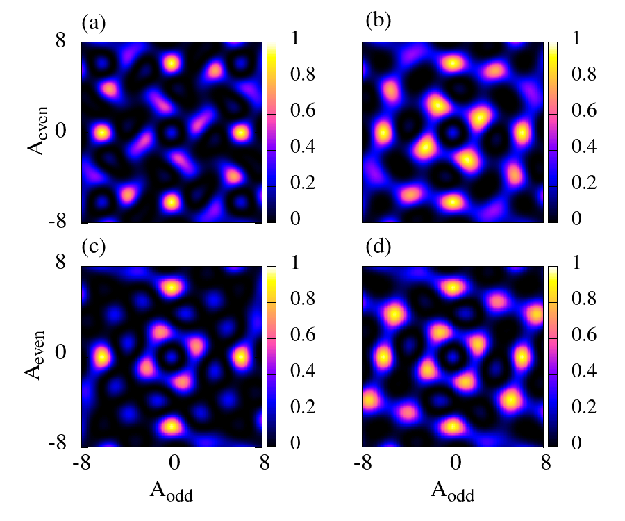
Fig.7(b) is the same result shown in Fig.4(b), repeated here to facilitate the comparison. Surprisingly, for the map is similar to that with in spite of having more terms. The symmetry of the cosine and sine terms on and effectively constraints the possible solutions so the fidelity map is similar to that with . The same will happen in all sequences with even number of pulses. Solutions with odd number of pulses always provide richer fidelity maps, with higher fidelities available at more protocols. Although solutions can be easily generalized to any number of pulses, the highly-constraining nature of the ESOP schemes makes these protocols probably unnecessary, as they do not improve the results of the SOP. This might not be the case, however, when the effects of noise are taken into account. Intensity fluctuations that are proportional to the peak intensity of the lasers will affect more strongly those protocols that use stronger fields, that is, with larger pulse areas. The effect will be dominated by the pulse with larger area in the sequence, rather than by the sum of all pulse areas. It is possible to find optimal protocols with -pulses that distribute the pulse area among all the fields, so that the peak intensities in each field are smaller than in the similar protocol with -pulses. Obviously, if the parameters are unconstrained and full optimization is performed to find the solutions, then having more pulses and more parameters will clearly provide more protocols, as will be shown in subsequent studies.
VI Summary and Discussion
We have studied the performance of a two-qubit gate in a denser array of trapped atoms under perfect conditions (zero temperature, no external noise) in the regime of strong Rydberg blockade. Extending the well-known Jaksch protocol (JP), we have proposed a novel implementation, called the Symmetric Orthogonal Protocol (SOP), by controlling both the pulse sequence and the spatial properties of the fields, using structured light. The Hamiltonian of the light-atomic system was modeled using geometrical factors, that measure the amplitudes of the fields at the location of the qubits, allowing to obtain analytical formulas for the propagators.
From the time-domain perspective, the scheme generalizes the JP with three pulses that operate symmetrically in time, but with different pulse areas. From the spatial-domain perspective, the scheme uses hybrid modes of light. The geometrical factors form orthogonal vectors in the SOP, which allow to decouple the effect of odd and even pulses in the sequence, by using a coherent dark state that drives the population through the Rydberg states. The SOP protocol is as robust as the JP to variations in the pulse areas and more robust to changes in the position of the atoms along certain directions. Implementations with maximal fidelity form a lattice of solutions in the space of the pulse areas, which is rotated with respect to the lattice of solutions in the JP.
We have analyzed the effect of adding a third atom in the proximity of the two-qubit system. The fidelity in the SOP decays more rapidly than in the JP. High-fidelity solutions could not be found by just controlling the position of the third atom, but rather the geometrical factors at the first two-qubits must be optimized for every choice of pulse areas. Finally, we have proposed natural generalizations of the SOP to multipulse sequences, showing that sequences with odd number of pulses form richer lattices with a denser number of solutions than sequences with even number of pulses.
The SOP shows great promise for possible implementations of fast two-qubit gates. Working in the strong dipole blockade regime () one can in principle accelerate the gate a factor of . However, high fidelities are achieved in the SOP using larger pulse areas than in the JP, typically by a factor of to . Hence, gates with comparable or slightly worse fidelity and equal robustness could be in principle prepared at durations of the order of to times shorter, moving the scale from the microsecond to the nanosecond regime.
From the physical point of view, the SOP operates as the JP, so one can expect a similar sensitivity to decoherence and noise. However, because the atoms are much closer, the dipole blockade is much larger and the gate time is much shorter, the effect of the thermal motion of the atoms, Rydberg-Rydberg couplings or spontaneous emission, is almost negligible. Only fluctuations in the field intensities (hence pulse areas) as well as in the position of the atoms, leading to changes in the geometrical factors, have some impact on the fidelities. Preliminary estimates of these effects show about % reduction of the peak fidelities working at K temperature. However, further comprehensive studies are needed to properly quantify the effect of noise. Equally important will be to assess the current limitations (time durations, spatial resolution) in using structured light specific to the proposed design. Hybrid modes of light may find many applications in quantum technologies, beyond the present proposal. On the other hand, full optimization of both the pulse areas and the geometrical factors will probably allow refinements in the implementations, the surface of which has only been explored in the present contribution.
Conflicts of interest
There are no conflicts to declare.
Acknowledgements
This research was supported by the Quantum Computing Technology Development Program (NRF-2020M3E4A1079793) and the National Creative Research Initiative Grant (NRF- 2014R1A3A2030423). IRS also thanks the BK21 program (Global Visiting Fellow) for the stay during which this project started and for support from MINECO CTQ2015-65033-P and MINECO PID2021-122796NB-I00. SS acknowledges support from the Center for Electron Transfer funded by the Korea government(MSIT)(NRF-2021R1A5A1030054).
References
- Mei et al. [2022] Y. Mei, Y. Li, H. Nguyen, P. R. Berman and A. Kuzmich, Phys. Rev. Lett., 2022, 128, 123601.
- Dudin and Kuzmich [2012] Y. O. Dudin and A. Kuzmich, Science, 2012, 336, 887–889.
- Adams et al. [2019] C. S. Adams, J. D. Pritchard and J. P. Shaffer, Journal of Physics B: Atomic, Molecular and Optical Physics, 2019, 53, 012002.
- Pritchard et al. [2010] J. D. Pritchard, D. Maxwell, A. Gauguet, K. J. Weatherill, M. P. A. Jones and C. S. Adams, Phys. Rev. Lett., 2010, 105, 193603.
- Chew et al. [2022] Y. Chew, T. Tomita, T. P. Mahesh, S. Sugawa, S. de Léséleuc and K. Ohmori, Nature Photonics, 2022, 16, 724–729.
- Brion et al. [2007] E. Brion, K. Mølmer and M. Saffman, Phys. Rev. Lett., 2007, 99, 260501.
- Pohl et al. [2010] T. Pohl, E. Demler and M. D. Lukin, Phys. Rev. Lett., 2010, 104, 043002.
- Lukin et al. [2001] M. D. Lukin, M. Fleischhauer, R. Cote, L. M. Duan, D. Jaksch, J. I. Cirac and P. Zoller, Phys. Rev. Lett., 2001, 87, 037901.
- Maller et al. [2015] K. M. Maller, M. T. Lichtman, T. Xia, Y. Sun, M. J. Piotrowicz, A. W. Carr, L. Isenhower and M. Saffman, Phys. Rev. A, 2015, 92, 022336.
- Zeng et al. [2017] Y. Zeng, P. Xu, X. He, Y. Liu, M. Liu, J. Wang, D. J. Papoular, G. V. Shlyapnikov and M. Zhan, Phys. Rev. Lett., 2017, 119, 160502.
- Levine et al. [2018] H. Levine, A. Keesling, A. Omran, H. Bernien, S. Schwartz, A. S. Zibrov, M. Endres, M. Greiner, V. Vuletić and M. D. Lukin, Phys. Rev. Lett., 2018, 121, 123603.
- Urban et al. [2009] E. Urban, T. A. Johnson, T. Henage, L. Isenhower, D. D. Yavuz, T. G. Walker and M. Saffman, Nature Physics, 2009, 5, 110–114.
- Saffman et al. [2010] M. Saffman, T. G. Walker and K. Mølmer, Rev. Mod. Phys., 2010, 82, 2313–2363.
- Wilk et al. [2010] T. Wilk, A. Gaëtan, C. Evellin, J. Wolters, Y. Miroshnychenko, P. Grangier and A. Browaeys, Phys. Rev. Lett., 2010, 104, 010502.
- Zhang et al. [2010] X. L. Zhang, L. Isenhower, A. T. Gill, T. G. Walker and M. Saffman, Phys. Rev. A, 2010, 82, 030306.
- Walker and Saffman [2012] T. G. Walker and M. Saffman, Advances in Atomic, Molecular, and Optical Physics, Academic Press, 2012, vol. 61, pp. 81–115.
- Gaëtan et al. [2009] A. Gaëtan, Y. Miroshnychenko, T. Wilk, A. Chotia, M. Viteau, D. Comparat, P. Pillet, A. Browaeys and P. Grangier, Nature Physics, 2009, 5, 115–118.
- Picken et al. [2018] C. J. Picken, R. Legaie, K. McDonnell and J. D. Pritchard, Quantum Science and Technology, 2018, 4, 015011.
- Graham et al. [2022] T. M. Graham, Y. Song, J. Scott, C. Poole, L. Phuttitarn, K. Jooya, P. Eichler, X. Jiang, A. Marra, B. Grinkemeyer, M. Kwon, M. Ebert, J. Cherek, M. T. Lichtman, M. Gillette, J. Gilbert, D. Bowman, T. Ballance, C. Campbell, E. D. Dahl, O. Crawford, N. S. Blunt, B. Rogers, T. Noel and M. Saffman, Nature, 2022, 604, 457–462.
- Malinovskaya [2017] S. A. Malinovskaya, Opt. Lett., 2017, 42, 314–317.
- Pachniak and Malinovskaya [2021] E. Pachniak and S. A. Malinovskaya, Scientific Reports, 2021, 11, 12980.
- Thomas et al. [2022] P. Thomas, L. Ruscio, O. Morin and G. Rempe, Nature, 2022, 608, 667–681.
- Weimer et al. [2010] H. Weimer, M. Müller, I. Lesanovsky, P. Zoller and H. P. Büchler, Nature Physics, 2010, 6, 382–388.
- Bernien et al. [2017] H. Bernien, S. Schwartz, A. Keesling, H. Levine, A. Omran, H. Pichler, S. Choi, A. S. Zibrov, M. Endres, M. Greiner, V. Vuletić and M. D. Lukin, Nature, 2017, 551, 579–584.
- Keesling et al. [2019] A. Keesling, A. Omran, H. Levine, H. Bernien, H. Pichler, S. Choi, R. Samajdar, S. Schwartz, P. Silvi, S. Sachdev, P. Zoller, M. Endres, M. Greiner, V. Vuletić and M. D. Lukin, Nature, 2019, 568, 207–211.
- Kim et al. [2018] H. Kim, Y. Park, K. Kim, H.-S. Sim and J. Ahn, Phys. Rev. Lett., 2018, 120, 180502.
- Jaksch et al. [2000] D. Jaksch, J. I. Cirac, P. Zoller, S. L. Rolston, R. Côté and M. D. Lukin, Phys. Rev. Lett., 2000, 85, 2208–2211.
- Isenhower et al. [2011] L. Isenhower, M. Saffman and K. Mølmer, Quantum Information Processing, 2011, 10, 755.
- Parigi et al. [2012] V. Parigi, E. Bimbard, J. Stanojevic, A. J. Hilliard, F. Nogrette, R. Tualle-Brouri, A. Ourjoumtsev and P. Grangier, Phys. Rev. Lett., 2012, 109, 233602.
- Mølmer et al. [2011] K. Mølmer, L. Isenhower and M. Saffman, Journal of Physics B: Atomic, Molecular and Optical Physics, 2011, 44, 184016.
- Müller et al. [2009] M. Müller, I. Lesanovsky, H. Weimer, H. P. Büchler and P. Zoller, Phys. Rev. Lett., 2009, 102, 170502.
- Shi [2018] X.-F. Shi, Phys. Rev. Applied, 2018, 9, 051001.
- Khazali and Mølmer [2020] M. Khazali and K. Mølmer, Phys. Rev. X, 2020, 10, 021054.
- Wu et al. [2021] J.-L. Wu, Y. Wang, J.-X. Han, Y. Jiang, J. Song, Y. Xia, S.-L. Su and W. Li, Phys. Rev. Appl., 2021, 16, 064031.
- Chu et al. [1985] S. Chu, L. Hollberg, J. E. Bjorkholm, A. Cable and A. Ashkin, Phys. Rev. Lett., 1985, 55, 48–51.
- Raab et al. [1987] E. L. Raab, M. Prentiss, A. Cable, S. Chu and D. E. Pritchard, Phys. Rev. Lett., 1987, 59, 2631–2634.
- Gibble et al. [1992] K. E. Gibble, S. Kasapi and S. Chu, Opt. Lett., 1992, 17, 526–528.
- Šibalić and Adams [2018] N. Šibalić and C. S. Adams, Rydberg Physics, IOP Publishing, 2018.
- Gallagher [1994] T. F. Gallagher, Rydberg Atoms, Cambridge University Press, 1994.
- Goerz et al. [2014] M. H. Goerz, E. J. Halperin, J. M. Aytac, C. P. Koch and K. B. Whaley, Phys. Rev. A, 2014, 90, 032329.
- Bergmann et al. [1998] K. Bergmann, H. Theuer and B. W. Shore, Rev. Mod. Phys., 1998, 70, 1003–1025.
- Vitanov et al. [2001] N. V. Vitanov, T. Halfmann, B. W. Shore and K. Bergmann, Annual Review of Physical Chemistry, 2001, 52, 763–809.
- Petrosyan et al. [2017] D. Petrosyan, F. Motzoi, M. Saffman and K. Mølmer, Phys. Rev. A, 2017, 96, 042306.
- Graham et al. [2019] T. M. Graham, M. Kwon, B. Grinkemeyer, Z. Marra, X. Jiang, M. T. Lichtman, Y. Sun, M. Ebert and M. Saffman, Phys. Rev. Lett., 2019, 123, 230501.
- Levine et al. [2019] H. Levine, A. Keesling, G. Semeghini, A. Omran, T. T. Wang, S. Ebadi, H. Bernien, M. Greiner, V. Vuletić, H. Pichler and M. D. Lukin, Phys. Rev. Lett., 2019, 123, 170503.
- Malinovsky et al. [2014] V. S. Malinovsky, I. R. Sola and J. Vala, Phys. Rev. A, 2014, 89, 032301.
- Malinovsky and Sola [2004] V. S. Malinovsky and I. R. Sola, Phys. Rev. A, 2004, 70, 042304.
- Malinovsky and Sola [2004] V. S. Malinovsky and I. R. Sola, Phys. Rev. Lett., 2004, 93, 190502.
- Malinovsky and Sola [2006] V. S. Malinovsky and I. R. Sola, Phys. Rev. Lett., 2006, 96, 050502.
- Palao and Kosloff [2003] J. P. Palao and R. Kosloff, Phys. Rev. A, 2003, 68, 062308.
- Goerz et al. [2014] M. H. Goerz, D. M. Reich and C. P. Koch, New Journal of Physics, 2014, 16, 055012.
- Caneva et al. [2011] T. Caneva, T. Calarco and S. Montangero, Phys. Rev. A, 2011, 84, 022326.
- Goerz et al. [2011] M. H. Goerz, T. Calarco and C. P. Koch, Journal of Physics B: Atomic, Molecular and Optical Physics, 2011, 44, 154011.
- Theis et al. [2016] L. S. Theis, F. Motzoi, F. K. Wilhelm and M. Saffman, Phys. Rev. A, 2016, 94, 032306.
- Comparat and Pillet [2010] D. Comparat and P. Pillet, J. Opt. Soc. Am. B, 2010, 27, A208–A232.
- Tong et al. [2004] D. Tong, S. M. Farooqi, J. Stanojevic, S. Krishnan, Y. P. Zhang, R. Côté, E. E. Eyler and P. L. Gould, Phys. Rev. Lett., 2004, 93, 063001.
- Walker and Saffman [2008] T. G. Walker and M. Saffman, Phys. Rev. A, 2008, 77, 032723.
- Pohl and Berman [2009] T. Pohl and P. R. Berman, Phys. Rev. Lett., 2009, 102, 013004.
- Rittenhouse and Sadeghpour [2010] S. T. Rittenhouse and H. R. Sadeghpour, Phys. Rev. Lett., 2010, 104, 243002.
- Shaffer et al. [2018] J. P. Shaffer, S. T. Rittenhouse and H. R. Sadeghpour, Nature Communications, 2018, 9, 1965.
- Murty [1964] M. V. R. K. Murty, Appl. Opt., 1964, 3, 1192–1194.
- Forbes et al. [2021] A. Forbes, M. de Oliveira and M. R. Dennis, Nature Photonics, 2021, 15, 253–262.
- Rubinsztein-Dunlop et al. [2016] H. Rubinsztein-Dunlop, A. Forbes, M. V. Berry, M. R. Dennis, D. L. Andrews, M. Mansuripur, C. Denz, C. Alpmann, P. Banzer, T. Bauer, E. Karimi, L. Marrucci, M. Padgett, M. Ritsch-Marte, N. M. Litchinitser, N. P. Bigelow, C. Rosales-Guzmán, A. Belmonte, J. P. Torres, T. W. Neely, M. Baker, R. Gordon, A. B. Stilgoe, J. Romero, A. G. White, R. Fickler, A. E. Willner, G. Xie, B. McMorran and A. M. Weiner, Journal of Optics, 2016, 19, 013001.
- Rice and Zhao [2000] S. Rice and M. Zhao, Optical Control of Molecular Dynamics, John Wiley & Sons, Ltd, 2000.
- Shapiro and Brummer [2011] M. Shapiro and P. Brummer, Quantum Control of Molecular Processes, John Wiley & Sons, Ltd, 2011.
- Chang et al. [2016] B. Y. Chang, I. R. Sola and S. Shin, International Journal of Quantum Chemistry, 2016, 116, 608–621.
- Shore [2011] B. W. Shore, Manipulating Quantum Structures Using Laser Pulses, Cambridge University Press, 2011.
- Berman and Malinovsky [2011] P. R. Berman and V. S. Malinovsky, Principles of Laser Spectroscopy and Quantum Optics, Princeton University Press, 2011.
- Sola et al. [2018] I. R. Sola, B. Y. Chang, S. A. Malinovskaya and V. S. Malinovsky, Advances In Atomic, Molecular, and Optical Physics, Academic Press, 2018, vol. 67, pp. 151–256.
- Nelder and Mead [1965] J. A. Nelder and R. Mead, The Computer Journal, 1965, 7, 308–313.