figures/
MOTLEE: Distributed Mobile Multi-Object Tracking
with Localization Error Elimination
Abstract
We present MOTLEE, a distributed mobile multi-object tracking algorithm that enables a team of robots to collaboratively track moving objects in the presence of localization error. Existing approaches to distributed tracking make limiting assumptions regarding the relative spatial relationship of sensors, including assuming a static sensor network or that perfect localization is available. Instead, we develop an algorithm based on the Kalman-Consensus filter for distributed tracking that properly leverages localization uncertainty in collaborative tracking. Further, our method allows the team to maintain an accurate understanding of dynamic objects in the environment by realigning robot frames and incorporating frame alignment uncertainty into our object tracking formulation. We evaluate our method in hardware on a team of three mobile ground robots tracking four people. Compared to previous works that do not account for localization error, we show that MOTLEE is resilient to localization uncertainties, enabling accurate tracking in distributed, dynamic settings with mobile tracking sensors.
I Introduction
Reliable deployment of autonomous vehicles (AVs) requires that they have an accurate and up-to-date knowledge of the environment. Dynamic objects require particular care so that an AV can safely perform decision making in the presence of pedestrians and other moving agents. Multiple object tracking (MOT) provides a framework to allow an AV to detect, track, and forecast future motion of dynamic objects [1, 2]. However, field of view limitations can degrade an AV’s ability to sense the environment, and although state-of-the-art methods have shown increased accuracy and robustness by fusing multiple modality sensors that are rigidly attached to the AV [3, 4, 5], factors such as occlusion and sensing range can limit the effective field of view of MOT algorithms. These limitations have led to research on multi-view MOT [6, 7, 8, 9], which allows AV teams to collaboratively track dynamic objects [10].
Multi-view MOT, which uses multiple sensors networked together for tracking, has the benefit of an increased tracking coverage area, but requires accurate knowledge of the spatial relationships (i.e., the localization) between sensors so that measurements can be correctly interpreted. Existing methods typically assume either a static, calibrated sensor network [6, 11, 7, 8] or moving sensors within a known map and with perfect localization [10, 12, 13, 14]. However, in practice these assumptions are violated due to mis-calibration, environmental effects (e.g., vibration, temperature), or localization uncertainty, causing sensors’ local coordinate frames to become misaligned. Misaligned local frames can have disastrous consequences in multi-sensor estimation problems because data shared between sensors may be inconsistent, leading to incorrect data association and noisy signal recovery.
In the context of multi-view MOT for AVs, these frame misalignment issues can cause the team to generate false-positive tracks (i.e., tracks for objects that are not really there), which corrupt AVs’ understanding of the environment and thus negate the value of shared knowledge. Localization, and therefore frame alignment, will never be perfect; therefore, the multi-view MOT fusion process must understand this uncertainty. Object measurement noise must properly reflect both an AV’s own localization uncertainty and the uncertainty of frame alignment when measurements are sent to neighboring AVs. Thus, AVs with more localization uncertainty can have their measurements appropriately down-weighted relative to other AVs’ information. Otherwise, the estimation process may become over-confident about the wrong answer (i.e., filter inconsistency). Because we are interested in distributed MOT, which provides scalability, redundancy, and communication resilience [15, 16], frame alignment issues cannot be solved by a central authority and must be handled by each AV.
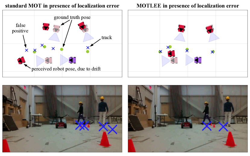
We address the issue of localization uncertainty in distributed mobile MOT by providing a decentralized mechanism for online frame alignment between pairs of robots. Further, we properly fuse measurements according to each robot’s localization uncertainty and relative frame alignment uncertainty. Our method, called MOTLEE (MOT with Localization Error Elimination) performs distributed tracking in the ground plane using the Kalman-Consensus filter (KCF) [17, 18] and corrects frame misalignment by using both static landmarks and dynamic objects that are co-visible between AVs. We demonstrate the performance of MOTLEE on a team of mobile ground robots tracking a group of pedestrians, shown in Fig. 1. We experimentally show that even a small amount of localization error (, ) causes existing methods to break down, while our method is able to maintain high accuracy. In summary, our contributions include:
-
1.
A decentralized algorithm for compensating for localization error between pairs of robots, relaxing assumptions made by state-of-the-art distributed MOT systems to enable distributed mobile MOT.
-
2.
A distributed MOT system that accounts for measurement uncertainty due to localization and frame alignment errors. Properly modelling the noise covariance prevents failed data association and over-confident estimation.
-
3.
Hardware demonstration of our distributed MOTLEE method with a team of three ground robots tracking four pedestrians. We show that our system, in the presence of localization error, is able to achieve a tracking accuracy very close to the ideal tracking accuracy of a system with perfect localization.
II Related Work
Tracking multiple objects using sensor observations is a well-studied task spanning multiple communities [19, 20, 21]. State-of-the-art systems employ tracking-by-detection, wherein object detections are associated across time and then fused to estimate object trajectories. Significant research has been devoted to improving these systems by focusing on improving data association [22, 23, 24], fusing multiple modalities [4, 3, 25], or using multiple sensors [6, 26, 27]. In the following discussion, we focus on works most relevant to localization uncertainty in the context of MOT.
II-A Multi-view MOT with Known Localization
Multi-view MOT, sometimes referred to as multi-target multi-camera tracking (MTMCT), is most commonly performed with static cameras having known spatial relationships [6, 26, 8, 28, 11, 29], e.g., through extrinsic calibration. These systems may be centralized [6, 26] or distributed [8, 28, 11, 29]. In centralized systems, each sensor node sends information to a central fusion center, where all data is processed together in a common coordinate frame. Centralized methods typically achieve high tracking accuracy, but have the main disadvantages of using excessive communication and having a single point of failure. Distributed methods alleviate these disadvantages, but still typically assume that cameras are static and never perturbed, often requiring an offline calibration step beforehand. Pan-tilt-zoom (PTZ) cameras are static in position, but may rotate; however, these parameters are typically communicated to the other cameras so that coordinate frames align [28].
Mobile multi-view MOT systems also require knowledge of spatial relationships, which change over time. Kroeger et al. [12] performed centralized multi-view tracking using mobile cameras by localizing cameras in a dense map previously reconstructed using structure from motion. Ong et al. [30] proposed a decentralized particle filtering approach and tested it using multiple flight vehicles, but assume perfect localization in a common global frame (e.g., using GPS). Many mobile multi-view MOT systems arise in multirobot tasks, such as multi-target mapping [13], multi-target search and tracking [14, 31], and multi-target coverage control [32]. Shorinwa et al. [10] presented a distributed MOT algorithm based on consensus ADMM to enable collaborative tracking among AVs, but made strong assumptions about known data association from each measurement and perfect AV localization. Before these algorithms can be deployed on hardware in real-world scenarios, the perfect localization assumption must be relaxed.
II-B Single-view MOT with Unknown Localization
More effort has been made in relaxing the known localization assumption for the single-view (i.e., single robot) MOT case and is closely related to simultaneous localization and mapping methods. Wang et al. [33, 34, 35] first formulated the joint SLAM and MOT problem. In [35], the authors presented a maximum a posteriori (MAP) formulation of SLAMMOT using a Bayes network and implemented an approximate version that decouples the SLAM and MOT problem into two separate estimators for static and dynamic objects. Similarly, Choi et al. [36] presented a sampling-based method for simultaneously estimating object tracks and the camera’s ego-motion by leveraging static features in the scene. Recent works continue to build on these ideas for single-view MOT by leveraging factor graphs for 3D tracking and ego-motion estimation [37] or using MOT as a mechanism to improve visual SLAM accuracy [38].
II-C Multi-view MOT with Unknown Localization
Few works have considered localization uncertainty in multi-view MOT. Lin et al. [39] showed that local estimates of tracked objects could be used to estimate dynamic biases of collaborative static sensors. Their approach is specific to drift characteristic of range and bearing sensors, with which they create a constrained problem and solve for biases in each sensor. However, they do not not address spatial localization uncertainty experienced by mobile sensors, and their simulation results are limited, involving tracking a known number of targets without occlusions. Moratuwage et al. [40] presented a collaborative SLAM and tracking method based on random finite sets (RFS) and the probabilistic hypothesis density (PHD) filter. However, their algorithm is centralized and so requires robots to communicate all their data to a central machine. Ahmad et al. [41] formulated a joint, collaborative MOT and localization problem as a pose graph optimization for robotic soccer. They make the limiting assumption of known data association of measurements with static landmarks and tracked dynamic objects. Chen and Dames [32] recently proposed a distributed MOT algorithm, also based on RFS and the PHD filter. Their work introduces the notion of convex uncertainty Voronoi cells, which describes the area each robot is assigned to patrol. Because targets may cross cell boundaries, additional communication is required to transfer ownership of targets and to update the cells. Simulation results of their method are provided, however, the localization uncertainty everywhere along the robot’s path is assumed to be constant, which is not realistic.
III Distributed Mobile MOT
[pretex=,width=]block_diagram
We formulate distributed MOT within the Kalman-Consensus filter (KCF) framework [17, 18] and adopt the distributed track manager methodology of Casao et al. [8]. Consider a network of robots with the communication graph , where each vertex in the graph is a robot. We assume that the graph is connected (i.e., a path exists between any two vertices) and denote the one-hop neighbors of robot as . Quantities associated with the -th robot are denoted with subscript . An unknown number of moving objects are observed by the robot team, with each object modeled by a discrete-time linear dynamic system
| (1) |
where and are the transition and measurement matrices, respectively, and and are zero-mean independent Gaussian process and measurement noise with covariance matrices and , respectively. We define a track as the estimate corresponding to measurements of an object. The -th robot maintains its own local bank of tracks, denoted . The -th track has an associated error covariance , along with other variables including track lifetime and number of missed detections, which are used for track management. Ideally, each track corresponds to a single object, but this may not always be the case due to noise, partial measurements, and clutter.
Typical single-view MOT systems consist of the following stages: 1) measurement-to-track data association, 2) data fusion, and 3) track management (initialization and deletion). In distributed MOT, measurement-to-track data association is performed locally, while data fusion and track management is performed in a distributed manner. Additionally, distributed track-to-track data association is required to ensure the team maintains a consistent understanding when new tracks are shared. Furthermore, because the robots are mobile and have localization uncertainty, robots must transform measurements and their covariances into their neighbors’ coordinate frames when sharing data. These stages are depicted in the block diagram in Fig. 2 and discussed in the following subsections.
III-A Localization Uncertainty
Because the robots are mobile, they must localize themselves with respect to each other so that measurements from the -th robot can be used by its neighbors. We denote the pose of the -th robot at time as , where or , depending on the tracking scenario. Note that each robot’s local frame is defined as its initial frame, and is expressed with respect to robot ’s local frame. Because of localization errors (e.g., odometric drift), each robot only has access to an estimate of its pose, denoted , and its associated pose uncertainty . Tracks are expressed in the robot’s local frame and inter-robot frame alignments are required for data fusion.
Consensus on geometric quantities requires a shared coordinate frame. In particular, as robots communicate their local measurements to their neighbors, a pair of robots and must be able to transform measurements into the other’s frame. Supposing there exists a previous transform between their local frames, measurements can easily be transformed across robots. This previous transform can be found if robots are localizing within a shared reference map or if the robots start with known relative poses. However, in the presence of localization uncertainty, drift causes frame misalignment between pairs of robots.
Consider the scenario in Fig. 3, where, for simplicity and without loss of generality, robot has accumulated drift since time , but robot has not. At time , both robots make a measurement of a single object, denoted . Robot receives a measurement of the object, but due to drift, it is incorrectly mapped into its local frame. Since robot maps the object perfectly (no drift), the expression of in the frame is far from its measurement and so fusing these measurements results in a poor estimate of the position of . Instead, if was found and used, the effects of drift would be removed and , would be perfectly aligned. This example highlights the important role of —it allows robots to communicate coherently about measurements received in each other’s local frame. In Section IV, we will present methods for providing the estimate .
[pretex=,width=]localization_uncertainty
III-B Localization Uncertainty Propagation
Data association and fusion processes assume valid noise statistics. If the noise covariance is not representative of the true uncertainty, then data association can fail and fusion can incorrectly incorporate information. To account for localization uncertainty of robot , measurements must be properly combined when transforming into the local frame of robot . Following Smith, Self, and Cheeseman (SSC) [42], we parameterize the transformation using Euler angles and the pose composition (head-to-tail) combines the covariances of and as
| (2) |
where and are Jacobians encoding the transformation . This covariance, associated with the transformed measurement , are then used for making local data association decisions (see Section III-D). Similarly, when transforming a measurement for a neighboring robot using the relative transform , the measurement and covariance are transformed using the tail-to-tail method
| (3) | ||||
| (4) |
where is the Jacobian encoding the frame alignment .
III-C Kalman-Consensus Filter
The KCF is a distributed estimation algorithm with a peer-to-peer architecture [11], and like existing works [8, 11], we assume that sensor nodes are synchronized; however, this assumption can be relaxed as in the event-triggered KCF of [43]. At each timestep , each of the robots makes a set of observations . After local data association is solved (see Section III-D), new local measurements are fused with their associated track in the robot’s local bank . Because each robot makes noisy measurements in its own local frame, robots’ local estimates of a given track will differ. However, consensus is enabled through frame alignment estimates . Using the KCF allows the robots to reach consensus about track estimates via transformed local frames and enables sharing of measurements to produce more accurate estimates.
For clarity of exposition, we consider a single KCF iteration from the point of view of robot where its local copy of track is associated with the local measurement (see Section III-D). For brevity, we drop the superscripts and . The KCF performs consensus filtering in information form, thus, measurements are first transformed according to
| (5) |
where the measurement and its covariance are first transformed into the receiving neighbor’s frame according to (3) and (4). The -th robot then broadcasts the message to its neighbors. Once robot receives this message from each of its neighbors, the information is aggregated as
| (6) |
Each track is then updated with the fused information from all robots using the KCF update,
| (7) |
where is the Kalman gain in information form and is the error covariance of the track state. Finally, the covariance matrix is updated according to and .
III-D Local Data Association
Local data association (LDA) assesses which track best explains each measurement. We solve LDA using the global nearest neighbor (GNN) approach [20], which formulates the data association problem as a linear assignment problem using a matching cost given by the Mahalanobis distance
| (8) |
where is the innovation covariance. Note that we use the transformed measurement and covariance according to (2). We use a gating region defined by , so that for a measurement cannot be assigned to the track. GNN can be solved exactly and in polynomial time using the Hungarian algorithm [44].
III-E Track Management and Distributed Data Association
Track management is an important component of MOT systems. The distributed case involves robots making decisions about when to create new tracks and when to delete an existing track that has not recently received any new measurements. See Casao et al. [8] for an overview of performing distributed track management.
IV Frame Realignment Algorithm
For robot to communicate with robot about measurements in robot ’s own local frame, robots must have an estimate of the transformation between frames, . A poor estimate can prohibit robot from performing correct data association between its own measurement and the corrupted track information from robot , so it is crucial that is an accurate estimate of the robots’ true relative transformation. In this section, we will present a distributed method for eliminating error between robot frames using local maps of static landmarks and past dynamic object detections.
IV-A Realignment with Static Landmarks
The key concept is that frame alignment drift can be accounted for and eliminated by aligning objects observed by pairs of robots. Because drift can accumulate and change quickly, our method aims to promptly correct for drift online by creating small, local maps of recently observed static landmarks. With two local maps in hand, performing frame realignment with each neighbor involves three steps: first, associating landmarks between maps; second, applying a weighting to pairs of landmarks; and finally, performing point registration to compute .
To perform data association between two maps, we use iterative closest point (ICP) registration [45]. As ICP is a local method that requires a good initial guess, we use the previous estimate as a starting solution. Weights are applied to the associations found by ICP using the following weighting function to prioritize recent detections over old detections,
| (9) |
where a larger weight corresponds to a greater influence in the point registration and and are the number of frames since the corresponding static landmarks were last detected by robots or respectively. This is done to help account for drift that may have accumulated in older parts of the static local map.
The final step of the algorithm is to compute using Arun’s method [46] on the associated landmarks and respective weights. The transformation should be applied to all outgoing detections sent to robot to place the measurements properly in robot ’s frame.
IV-B Realignment with Tracked Objects
When a large enough number of dynamic objects are co-visible, robots can use these already tracked objects and their measurements to perform frame alignment. To determine whether dynamic object detections can be used to perform frame realignment, we define to be the number of concurrent, same-object detections between two agents and to be a threshold such that frame realignment is only performed with dynamic object detections when . If , then, static landmark realignment should be performed. Thus, with enough co-visibility for robots and to achieve a large , determining the realignment transformation can be done without performing any additional mapping and by only exchanging information about tracked objects.
One important difference between aligning static landmarks and tracked object measurements is that measurements from tracked objects have already been associated during the KCF information exchange. So, given two pairs of already-associated dynamic object measurements, and , we only need to find all pairs of detections , that occurred at the same time to perform realignment.
To realign frames with greater accuracy, we assign pairs of detections a weight that reflects the knowledge the agents have about the accuracy of the detection. We define the weighting function
| (10) |
which prioritizes aligning pairs of detections where both are consistent with the estimated state of the object, thus rejecting noisy detections and even detections that may have been associated incorrectly.
Once this step has been performed, a transformation is found using Arun’s method for registration [46]. Since aligned measurements , were already placed into robot ’s local frame, alignment of these measurements results in an intermediate correction transformation, . So, to conclude frame realignment, is updated with .
One problem that may arise with this algorithm is that it assumes that frame alignment between two robots is accurate enough that robots can associate detections of common objects. This will not be the case under severe frame misalignment. To address this issue and to give robots the ability to make correct data associations when frame error is large, we make (see Section III-D) reactive to the amount of detected frame misalignment, indicated by the magnitude of . The data association tolerance is scaled up when frame realignment yields a large and is returned back to its original value when frame realignment begins to yield a small .
V Experiments
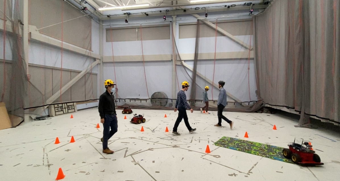
We evaluate our distributed mobile MOT system using two self-collected datasets generated using a team of ground robots in a room. Each robot was equipped with an Intel RealSense T265 Tracking Camera and an Intel RealSense L515 LiDAR Camera. A VICON motion capture system was used to collect ground truth pose information of robots, moving objects (pedestrians), and static landmarks (cones). For simplicity, we assume objects evolve according to (1) with a constant velocity motion model—thus the state of an object is defined to be . Each robot makes noisy 2D position observations in the ground plane so that the measurement model is defined as , where object measurements are made by processing CenterTrack [47] trained on the JRDB dataset [48, 49] on T265 left fisheye images. Although CenterTrack additionally provides IDs associated with detections (i.e., the CenterTrack network attempts to infer data association), we find these to be too noisy for practical use.
In addition to providing images used for person detection, the T265 stereo camera provides each robot with ego-motion estimation based on stereo visual odometry. Although each robot begins with knowledge of relative frame alignments (e.g., by initializing ), odometry drift quickly grows resulting in frame misalignments that cause failure of distributed data association and fusion of incoherent data in the KCF. Using our MOTLEE algorithm, we address these challenges by performing frame alignment and appropriately incorporating odometry and frame alignment uncertainty into shared measurement uncertainty.
We use MOTA [50] as the performance metric, given by
| (11) |
where is the number of ground truth objects missed in frame , is the number of false positives (i.e., perceived objects that are not found in frame ), is the number of mismatches, or objects that were reported under a different ID at time than the ID previously used for that object, and is the number of ground-truth objects in the scene. The components of MOTA are highly sensitive to the system’s ability to correctly perform data association and report the correct location of objects. This makes it a good candidate for measuring the effects of frame misalignment which causes data association errors and corrupts shared object detection measurements.
V-A Effects of Localization Error
We now demonstrate the performance of MOTLEE’s resilience to frame misalignment and localization error. First, we present our results in the context of a dataset taken with 5 pedestrians walking around our motion capture room with 4 stationary robots located around the perimeter. We use this dataset to artificially alter the localization error of each robot by initializing robot frame alignments with incorrect . In this way, we isolate the effects of localization error directly, without also introducing other error associated with performing mobile MOT, e.g., poor object detections from rolling-shutter distortion.
To represent the effects of inter-robot frame misalignment, artificial error is introduced into the system by adding a random, constant bias to the robot pose estimates at the start of a run by initializing , where is composed of random heading error and random translation error in the , plane with magnitude . We then capture the performance of the system for varying levels of and representing varying levels of localization uncertainty. We correlate the standard deviations and at a ratio of heading error per translation error. This ratio is the amount of heading error that would produce of error in the estimated position of a tracked object that is a distance of away from the robot, the approximate average distance between tracked objects and each robot in this dataset. To produce the following results, we run our full dataset through our MOT framework over 5 different samples at each uncertainty level to represent the average performance of the system as error is introduced.
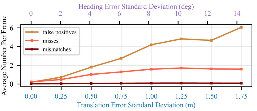
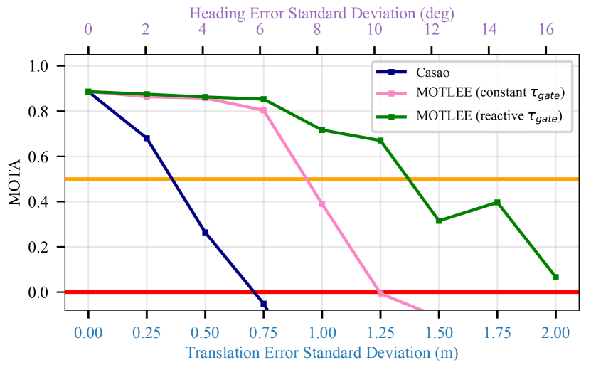
Fig. 5 and Fig. 6 show studies on the isolated effects of localization error. Fig. 5 decomposes the different pieces of MOTA and shows how misses and particularly false positives break a system’s MOT performance as localization error is introduced. Fig. 6 demonstrates that while Casao et al.’s [8] MOT algorithm rapidly breaks down with frame alignment error in the system, our MOTLEE algorithm is robust to localization error. Frame realignment is performed here by only aligning detections of dynamic objects.
V-B Mobile Experiment
In this section, we evaluate MOTLEE using a team of three mobile ground robots moving along pre-determined trajectories while four pedestrians walk among the robots. By nature of the small room that the experiment is run in, each robot follows a circular path in its assigned region of the room. Because of this, cameras have limited co-visibility of objects for approximately half of the time while they face the walls. In this experiment, there are too few shared dynamic detections to be used for frame realignment (), so static landmarks are used to realign frames. These landmarks are detected and mapped by each robot using the L515 camera. Detections of cones are made using YOLOv7 [51] with weights from [52]. The corresponding 3D points within the 2D bounding box are then identified by color thresholding and a 3D cone position is estimated using the median of these points. Cone detections are accumulated into local maps using the robot’s odometry combined with 3D cone detections to chain pairwise associations. Local maps are shared with neighbors at a frequency of , and frame alignment is performed using these local maps as they arrive. We represent the frame alignment uncertainty, , as a diagonal covariance matrix with elements determined by a linear scale of the difference between the current and most recent frame alignments. For this experiment we chose to set 100 recent dynamic object detections and .
Fig. 7 shows that using only noisy odometry readings without realignment only works well while localization error in the experiment is small, which only occurs at the beginning of the run. However, as more error is accumulated in each of the robot’s frame alignments, , the system fails to perform collaborative object tracking accurately. In contrast, when using our MOTLEE framework for realignment, we are able to perform near the level of the system using ground truth localization. We achieve an average MOTA of , similar to the ground truth performance of , while Casao et al. [8] breaks down due to the static camera assumption and scores a MOTA of .

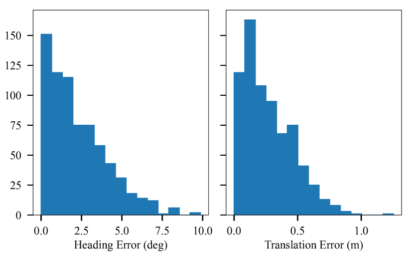
We also show the error between and in Fig. 8. With our MOTLEE frame realignment, we get a median error of heading error and translation error. Although we use the recorded data to run the system offline so that we can compare different localization scenarios, our algorithm can easily be run in real-time with each tracking and mapping cycle taking an average of with a standard deviation of and each frame alignment cycle taking an average of with a standard deviation of .
VI Conclusion
This work presents MOTLEE, a distributed MOT method that eliminates the effects of localization error on frame alignment between robots. We give methods for realigning frames between pairs of robots using dynamic object detections and static landmarks. Additionally, we show how to incorporate the uncertainty of localization and of frame alignment into the KCF. Using these methods, we show through hardware experiments that MOTLEE is robust to localization errors and is able to perform MOT at levels similar to a system with perfect localization. Future work includes removing the neccessity of an initial alignment (e.g., using [53]), incorporating frame alignment updates with a filter, integrating collaborative SLAM into MOTLEE, and running MOTLEE online and in real time.
References
- [1] A. Bewley, Z. Ge, L. Ott, F. Ramos, and B. Upcroft, “Simple online and realtime tracking,” in IEEE ICIP, 2016, pp. 3464–3468.
- [2] H.-k. Chiu, J. Li, R. Ambruş, and J. Bohg, “Probabilistic 3d multi-modal, multi-object tracking for autonomous driving,” in IEEE ICRA, 2021, pp. 14 227–14 233.
- [3] W. Zhang, H. Zhou, S. Sun, Z. Wang, J. Shi, and C. C. Loy, “Robust multi-modality multi-object tracking,” in IEEE/CVF ICCV, 2019.
- [4] A. Kim, A. Ošep, and L. Leal-Taixé, “Eagermot: 3d multi-object tracking via sensor fusion,” in IEEE ICRA, 2021, pp. 11 315–11 321.
- [5] Y. Wang, V. C. Guizilini, T. Zhang, Y. Wang, H. Zhao, and J. Solomon, “Detr3d: 3d object detection from multi-view images via 3d-to-2d queries,” in Conference on Robot Learning. PMLR, 2022.
- [6] F. Fleuret, J. Berclaz, R. Lengagne, and P. Fua, “Multicamera people tracking with a probabilistic occupancy map,” IEEE TPAMI, 2007.
- [7] T. Chavdarova, P. Baqué, S. Bouquet, A. Maksai, C. Jose, T. Bagautdinov, L. Lettry, P. Fua, L. Van Gool, and F. Fleuret, “Wildtrack: A multi-camera hd dataset for dense unscripted pedestrian detection,” in IEEE/CVF CVPR, 2018, pp. 5030–5039.
- [8] S. Casao, A. Naya, A. C. Murillo, and E. Montijano, “Distributed multi-target tracking in camera networks,” in IEEE ICRA, 2021.
- [9] P. Nguyen, K. G. Quach, C. N. Duong, N. Le, X.-B. Nguyen, and K. Luu, “Multi-camera multiple 3d object tracking on the move for autonomous vehicles,” in IEEE/CVF CVPR, 2022, pp. 2569–2578.
- [10] O. Shorinwa, J. Yu, T. Halsted, A. Koufos, and M. Schwager, “Distributed multi-target tracking for autonomous vehicle fleets,” in IEEE ICRA, 2020, pp. 3495–3501.
- [11] N. F. Sandell and R. Olfati-Saber, “Distributed data association for multi-target tracking in sensor networks,” in IEEE CDC, 2008.
- [12] T. Kroeger, R. Dragon, and L. Van Gool, “Multi-view tracking of multiple targets with dynamic cameras,” in GCPR. Springer, 2014.
- [13] P. Dames and V. Kumar, “Autonomous localization of an unknown number of targets without data association using teams of mobile sensors,” IEEE TASE, vol. 12, no. 3, pp. 850–864, 2015.
- [14] P. M. Dames, “Distributed multi-target search and tracking using the phd filter,” Autonomous robots, vol. 44, no. 3-4, pp. 673–689, 2020.
- [15] M. E. Liggins, C.-Y. Chong, I. Kadar, M. G. Alford, V. Vannicola, and S. Thomopoulos, “Distributed fusion architectures and algorithms for target tracking,” Proceedings of the IEEE, vol. 85, no. 1, 1997.
- [16] M. Taj and A. Cavallaro, “Distributed and decentralized multicamera tracking,” IEEE Signal Processing Magazine, vol. 28, no. 3, 2011.
- [17] R. Olfati-Saber, “Distributed kalman filtering for sensor networks,” in IEEE CDC, 2007, pp. 5492–5498.
- [18] ——, “Kalman-consensus filter: Optimality, stability, and performance,” in IEEE CDC, 2009, pp. 7036–7042.
- [19] S. S. Blackman, “Multiple-target tracking with radar applications,” Dedham, 1986.
- [20] Y. Bar-Shalom and X.-R. Li, Multitarget-multisensor tracking: principles and techniques. YBs Storrs, CT, 1995, vol. 19.
- [21] W. Luo, J. Xing, A. Milan, X. Zhang, W. Liu, and T.-K. Kim, “Multiple object tracking: A literature review,” Artificial Intelligence, 2021.
- [22] L. Zhang, Y. Li, and R. Nevatia, “Global data association for multi-object tracking using network flows,” in IEEE/CVF CVPR, 2008.
- [23] M. Yang, Y. Wu, and Y. Jia, “A hybrid data association framework for robust online multi-object tracking,” IEEE TIP, vol. 26, no. 12, 2017.
- [24] X. Weng, Y. Wang, Y. Man, and K. M. Kitani, “GNN3DMOT: Graph neural network for 3d multi-object tracking with 2d-3d multi-feature learning,” in IEEE/CVF CVPR, 2020, pp. 6499–6508.
- [25] X. Wang, C. Fu, Z. Li, Y. Lai, and J. He, “DeepFusionMOT: A 3d multi-object tracking framework based on camera-lidar fusion with deep association,” IEEE RA-L, vol. 7, no. 3, pp. 8260–8267, 2022.
- [26] E. Ristani and C. Tomasi, “Features for multi-target multi-camera tracking and re-identification,” in IEEE/CVF CVPR, June 2018.
- [27] Y. T. Tesfaye, E. Zemene, A. Prati, M. Pelillo, and M. Shah, “Multi-target tracking in multiple non-overlapping cameras using fast-constrained dominant sets,” IJCV, vol. 127, pp. 1303–1320, 2019.
- [28] C. Soto, B. Song, and A. K. Roy-Chowdhury, “Distributed multi-target tracking in a self-configuring camera network,” in IEEE CVPR, 2009.
- [29] H. V. Nguyen, H. Rezatofighi, B.-N. Vo, and D. C. Ranasinghe, “Distributed multi-object tracking under limited field of view sensors,” IEEE Transactions on Signal Processing, pp. 5329–5344, 2021.
- [30] L.-L. Ong, B. Upcroft, T. Bailey, M. Ridley, S. Sukkarieh, and H. Durrant-Whyte, “A decentralised particle filtering algorithm for multi-target tracking across multiple flight vehicles,” in IEEE/RSJ IROS, 2006, pp. 4539–4544.
- [31] R. Zahroof, J. Liu, L. Zhou, and V. Kumar, “Multi-robot localization and target tracking with connectivity maintenance and collision avoidance,” in IEEE ACC, 2023, pp. 1331–1338.
- [32] J. Chen and P. Dames, “Collision-free distributed multi-target tracking using teams of mobile robots with localization uncertainty,” in IEEE/RSJ IROS, 2020, pp. 6968–6974.
- [33] C.-C. Wang and C. Thorpe, “Simultaneous localization and mapping with detection and tracking of moving objects,” in IEEE ICRA, 2002.
- [34] C.-C. Wang, C. Thorpe, and S. Thrun, “Online simultaneous localization and mapping with detection and tracking of moving objects: Theory and results from a ground vehicle in crowded urban areas,” in IEEE ICRA, 2003, pp. 842–849.
- [35] C.-C. Wang, C. Thorpe, S. Thrun, M. Hebert, and H. Durrant-Whyte, “Simultaneous localization, mapping and moving object tracking,” IJRR, vol. 26, no. 9, pp. 889–916, 2007.
- [36] W. Choi, C. Pantofaru, and S. Savarese, “A general framework for tracking multiple people from a moving camera,” IEEE TPAMI, vol. 35, no. 7, pp. 1577–1591, 2012.
- [37] X. Tian, Z. Zhu, J. Zhao, G. Tian, and C. Ye, “DL-SLOT: Dynamic lidar slam and object tracking based on collaborative graph optimization,” arXiv preprint arXiv:2212.02077, 2022.
- [38] H. Zhang, H. Uchiyama, S. Ono, and H. Kawasaki, “Motslam: Mot-assisted monocular dynamic slam using single-view depth estimation,” in IEEE/RSJ IROS, 2022, pp. 4865–4872.
- [39] X. Lin, Y. Bar-Shalom, and T. Kirubarajan, “Exact multisensor dynamic bias estimation with local tracks,” IEEE TAES, 2004.
- [40] D. Moratuwage, B.-N. Vo, and D. Wang, “Collaborative multi-vehicle slam with moving object tracking,” in IEEE ICRA, 2013.
- [41] A. Ahmad, G. D. Tipaldi, P. Lima, and W. Burgard, “Cooperative robot localization and target tracking based on least squares minimization,” in IEEE ICRA, 2013, pp. 5696–5701.
- [42] R. Smith, M. Self, and P. Cheeseman, Estimating Uncertain Spatial Relationships in Robotics. Springer, 1990, pp. 167–193.
- [43] W. Li, Y. Jia, and J. Du, “Event-triggered kalman consensus filter over sensor networks,” IET CTA, pp. 103–110, 2016.
- [44] H. W. Kuhn, “The hungarian method for the assignment problem,” Naval Research Logistics Quarterly, vol. 2, no. 1-2, pp. 83–97, 1955.
- [45] P. J. Besl and N. D. McKay, “Method for registration of 3-d shapes,” in Sensor fusion IV: control paradigms and data structures, vol. 1611. Spie, 1992, pp. 586–606.
- [46] K. S. Arun, T. S. Huang, and S. D. Blostein, “Least-squares fitting of two 3-d point sets,” IEEE TPAMI, no. 5, pp. 698–700, 1987.
- [47] X. Zhou, V. Koltun, and P. Krähenbühl, “Tracking objects as points,” ECCV, 2020.
- [48] R. Martίn-Martίn, M. Patel, H. Rezatofighi, A. Shenoi, J. Gwak, E. Frankel, A. Sadeghian, and S. Savarese, “JRDB: A dataset and benchmark of egocentric robot visual perception of humans in built environments,” IEEE TPAMI, vol. 45, no. 6, pp. 6748–6765, 2023.
- [49] C. W. Anderson and J. P. How, “Implementation of vision-based navigation for pedestrian environments,” Master’s thesis, MIT, 2022.
- [50] K. Bernardin and R. Stiefelhagen, “Evaluating multiple object tracking performance: the CLEAR MOT metrics,” EURASIP Journal on Image and Video Processing, vol. 2008, pp. 1–10, 2008.
- [51] C.-Y. Wang, A. Bochkovskiy, and H.-Y. M. Liao, “YOLOv7: Trainable bag-of-freebies sets new state-of-the-art for real-time object detectors,” arXiv preprint arXiv:2207.02696, 2022.
- [52] M. Krupczak, “Coneslayer: Cone detection weights for yolov7,” [Online]. Available: https://github.com/mkrupczak3/Coneslayer.
- [53] P. C. Lusk, K. Fathian, and J. P. How, “CLIPPER: A graph-theoretic framework for robust data association,” in IEEE ICRA, 2021.