Hyperon signatures in the PANDA experiment at FAIR
Abstract
We present a detailed simulation study of the signatures from the sequential decays of the triple-strange process in the PANDA central tracking system with focus on hit patterns and precise time measurement. We present a systematic approach for studying physics channels at the detector level and develop input criteria for tracking algorithms and trigger lines. Finally, we study the beam momentum dependence on the reconstruction efficiency for the PANDA detector.
keywords:
PANDA , FAIR , Hyperons , Track Reconstruction[1]organization=Joint Institute for Nuclear Research, city=Dubna, country=Russia \affiliation[2]organization=A.A. Logunov Institute for High Energy Physics of the National Research Centre “Kurchatov Institute”, city=Protvino, country=Russia \affiliation[3]organization=Johannes Gutenberg-Universität Institut für Kernphysik, city=Mainz, country=Germany \affiliation[4]organization=Helmholtz-Institut Mainz, city=Mainz, country=Germany \affiliation[5]organization=Ruhr-Universität Bochum Institut für Experimentalphysik I, city=Bochum, country=Germany \affiliation[6]organization=Uppsala Universitet Institutionen för fysik och astronomi, city=Uppsala, country=Sweden \affiliation[7]organization=GSI Helmholtzzentrum für Schwerionenforschung GmbH, city=Darmstadt, country=Germany \affiliation[8]organization=European Organization for Nuclear Research (CERN), city=Geneva, country=Switzerland \affiliation[9]organization=Forschungszentrum Jülich Institut für Kernphysik, city=Jülich, country=Germany \affiliation[10]organization=Stefan Meyer Institute, city=Wien, country=Austria \affiliation[11]organization=Budker Institute of Nuclear Physics, city=Novosibirsk, country=Russia \affiliation[12]organization=Stockholms Universitet, city=Stockholm, country=Sweden \affiliation[13]organization=FAIR Facility for Antiproton and Ion Research in Europe, city=Darmstadt, country=Germany \affiliation[14]organization=Department of Physics Doguş University, city=Istanbul, country=Turkey \affiliation[15]organization=University of Tehran, city=Tehran, country=Iran \affiliation[16]organization=Institute for Theoretical and Experimental Physics named by A.I. Alikhanov of National Research Centre ”Kurchatov Institute”, city=Moscow, country=Russia \affiliation[17]organization=Moscow Power Engineering Institute, city=Moscow, country=Russia \affiliation[18]organization=Università Politecnica delle Marche-Ancona, city=Ancona, country=Italy \affiliation[19]organization=Justus-Liebig-Universität Gießen II. Physikalisches Institut, city=Gießen, country=Germany \affiliation[20]organization=Università di Brescia, city=Brescia, country=Italy \affiliation[21]organization=Novosibirsk State University, city=Novosibirsk, country=Russia \affiliation[22]organization=Westfälische Wilhelms-Universität Münster, city=Münster, country=Germany \affiliation[23]organization=Dipartimento di Fisica Università di Pavia INFN Sezione di Pavia, city=Pavia, country=Italy \affiliation[24]organization=Friedrich-Alexander-Universität Erlangen-Nürnberg, city=Erlangen, country=Germany \affiliation[25]organization=Dept of Physics University of Genova and INFN-Genova, city=Genova, country=Italy \affiliation[26]organization=Institutul National de C&D pentru Fizica si Inginerie Nucleara ”Horia Hulubei”, city=Bukarest-Magurele, country=Romania \affiliation[27]organization=Synchrotron Light Research Institute, city=Nakhon Ratchasima, country=Thailand \affiliation[28]organization=Università di Torino and INFN Sezione di Torino, city=Torino, country=Italy \affiliation[29]organization=INFN Sezione di Torino, city=Torino, country=Italy \affiliation[30]organization=Karlsruhe Institute of Technology Institute for Data Processing and Electronics, city=Karlsruhe, country=Germany \affiliation[31]organization=Kungliga Tekniska Högskolan, city=Stockholm, country=Sweden \affiliation[32]organization=Rheinische Friedrich-Wilhelms-Universität Bonn, city=Bonn, country=Germany \affiliation[33]organization=Florida State University, city=Tallahassee, country=U.S.A. \affiliation[34]organization=Bolu Abant Izzet Baysal University, city=Bolu, country=Turkey \affiliation[35]organization=University of Technology Institute of Applied Informatics, city=Cracow, country=Poland \affiliation[36]organization=University of West Bohemia, city=Pilsen, country=Czech Republic \affiliation[37]organization=National Research Centre ”Kurchatov Institute” B. P. Konstantinov Petersburg Nuclear Physics Institute Gatchina, city=St. Petersburg, country=Russia \affiliation[38]organization=Charles University Faculty of Mathematics and Physics, city=Prague, country=Czech Republic \affiliation[39]organization=AGH University of Science and Technology, city=Cracow, country=Poland \affiliation[40]organization=Sardar Vallabhbhai National Institute of Technology Applied Physics Department, city=Surat, country=India \affiliation[41]organization=University of Glasgow, city=Glasgow, country=United Kingdom \affiliation[42]organization=Suranaree University of Technology, city=Nakhon Ratchasima, country=Thailand \affiliation[43]organization=Goethe-Universität, city=Institut für Kernphysik, country=Frankfurt \affiliation[44]organization=University of Science and Technology of China, city=Hefei, country=China \affiliation[45]organization=Czech Technical University Faculty of Nuclear Sciences and Physical Engineering, city=Prague, country=Czech Republic \affiliation[46]organization=Nankai University, city=Nankai, country=China \affiliation[47]organization=Gauhati University Physics Department, city=Guwahati, country=India \affiliation[48]organization=Universität Basel, city=Basel, country=Switzerland \affiliation[49]organization=Research Institute for Nuclear Problems Belarus State University, city=Minsk, country=Belarus \affiliation[50]organization=National Centre for Nuclear Research, city=Warsaw, country=Poland \affiliation[51]organization=Instytut Fizyki Uniwersytet Jagiellonski, city=Cracow, country=Poland \affiliation[52]organization=IFJ Institute of Nuclear Physics PAN, city=Cracow, country=Poland \affiliation[53]organization=Universität Heidelberg, city=Heidelberg, country=Germany \affiliation[54]organization=University of Wisconsin Oshkosh, city=Oshkosh, country=U.S.A. \affiliation[55]organization=Chinese Academy of Science Institute of Modern Physics, city=Lanzhou, country=China \affiliation[56]organization=Institute of High Energy Physics Chinese Academy of Sciences, city=Beijing, country=China \affiliation[57]organization=Energy and Sustainability Research Institute (ESRIG) University of Groningen, city=Groningen, country=Netherlands \affiliation[58]organization=INFN Laboratori Nazionali di Frascati, city=Frascati, country=Italy \affiliation[59]organization=National Research Nuclear University MEPhI (Moscow Engineering Physics Institute), city=Moscow, country=Russia \affiliation[60]organization=Istanbul Okan University, city=Istanbul, country=Turkey \affiliation[61]organization=University of South China, city=Hengyang, country=China \affiliation[62]organization=INFN Laboratori Nazionali di Legnaro, city=Legnaro, country=Italy \affiliation[63]organization=Northwestern University, city=Evanston, country=U.S.A. \affiliation[64]organization=IRFU CEA Université Paris-Saclay, city=Gif-sur-Yvette Cedex, country=France \affiliation[65]organization=University of Edinburgh, city=Edinburgh, country=United Kingdom \affiliation[66]organization=Giresun University, city=Giresun, country=Turkey
1 Introduction
Strange hyperons, i.e. baryons containing at least one strange quark, have been proven to be powerful diagnostic tools for the strong interaction and fundamental symmetries [1, 2, 3, 4]. In the future PANDA (antiProton ANnihilation at DArmstadt) experiment at FAIR (Facility for Antiproton and Ion Research) [5] hyperon-antihyperon pairs will be produced in annihilations at beam momenta ranging from 1.5 GeV/c to 15.0 GeV/c. The experiment has the potential to take the field of hyperon physics to a new level, as demonstrated for single- and double-strange hyperons in Refs. [6, 7, 8, 9]. The broad kinematic range of the HESR accelerator and the versatility of the PANDA detector also enables studies of the triple-strange hyperon. The hyperon played a crucial role in the development of modern hadron physics: its experimental discovery in 1964 [10] confirmed its existence as predicted by the Eight-fold Way [11]. Large-scale studies of the hyperon and its antiparticle, the , offers unique opportunities to study strong interaction dynamics [12] and fundamental symmetries [13, 14]. Furthermore, hyperon-antihyperon pair studies close to the kinematic threshold, where the produced pair is in a relative s-wave, provide a probe of the interaction potential. This, in turn, is an important component in the understanding of the hyperon internal structure [15] as well as the role of strangeness in macroscopic objects such as neutron stars [16].
For hyperons decaying into a baryon and a pion (such as the , the isotriplet states and the isodoublet states), the major part of the excess energy is generally transferred to the baryon due to momentum conservation. As a consequence, near the kinematic threshold the daughter pion is emitted with a very small momentum and may hence not reach the detectors. In the decay, the momentum is shared more equally between the and the kaon which implies that the decay products have a larger chance to be detected also close to the production threshold. Nevertheless, the is to date less explored than its single- and double-strange siblings. Most existing measurements of the properties are based on small data samples of for example 4,035 events [17, 18].
The expected yields of single- and double-strange hyperons in PANDA are large, typically between 104 - 106 events per day at the initial luminosity [6]. The hyperon on the other hand has never been studied with antiproton beams before and the production cross section is unknown. The reconstruction efficiency for tracks from the full process would provide a first estimate of the feasibility for future hyperon studies with PANDA.
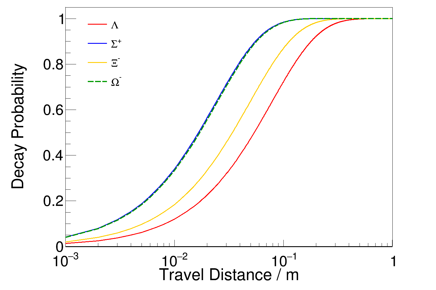
Ground-state hyperons like the and its daughter, the , decay weakly with a life-time of approximately 10-10s. This means that when produced in accelerator experiments at the GeV scale, they can travel a distance of centimeters or even up to a meter before decaying. In Fig. 1, this is illustrated for some hyperons by the decay probability plotted against the distance traveled. The relatively long life-time gives rise to a distinct event topology with a decay vertex that is separated from the production vertex by a measurable distance. This has the advantage that it enables a very efficient suppression of background channels, but it also comes with a challenge: the major part of the standard track reconstruction algorithms on the market are optimised for particles originating at the point where the initial beam-target or beam-beam interaction takes place [19, 20], i.e. the Interaction Point (IP).
In order to maximally exploit the high interaction rates – of up to 20 MHz – in the PANDA experiment, an entirely software-based trigger system will be used. This will operate in real time on the data stream from the detector subsystems. Spatial information alone will not be sufficient to properly separate tracks from different events. Therefore, time information will be utilized in addition to perform 4D tracking [21] where time and spatial information are combined. For tracks starting at the interaction point, tracking can be simplified enormously by constraining the IP. This reduces the amount of data and allows for fast tracking and filtering algorithms. For hyperons, this approach will however not be feasible and therefore, hyperons need customized tracking solutions.
The goal of this paper is to develop criteria for 4D tracking and triggering in the PANDA target spectrometer by:
-
1.
Identifying relevant criteria describing detector signatures for specific hyperon event topologies.
-
2.
Evaluating these criteria for hyperons and their decay products.
-
3.
Investigating which detectors yield reliable time-stamps for the reconstruction of final state particles of hyperon decays.
-
4.
Determining the track efficiency for different beam momenta for pairs and their decay products.
The paper is organised as follows: In Section 2, the PANDA experiment at FAIR will be presented, with emphasis on the target spectrometer and the central tracking system of PANDA. In Section 3, the simulation studies are presented. The resulting detector signatures from the reaction are presented in Section 4. In particular, we present the track reconstruction efficiency of the reaction using the full PANDA detector as a function of the beam momentum. Finally, we discuss a possible layout of a software trigger scheme for selection in PANDA.
2 The PANDA Experiment at FAIR
The PANDA experiment, under construction at FAIR [22] in Darmstadt, Germany, will be the world’s next-generation facility for studies of the strong interaction and fundamental symmetries [5]. Combining an antiproton beam in the intermediate energy range with a detector covering almost 4 of the full solid angle provides unique conditions for hadron physics in general and hyperon physics in particular.
Antiprotons will be cooled and stored in the High Energy Storage Ring (HESR) [23]. In the early phase of operation [7], the HESR will be able to accumulate up to antiprotons in 1000 s. Stochastic cooling will result in a relative beam momentum resolution better than . The antiproton beam will impinge on a hydrogen cluster jet or pellet target, yielding an average luminosity of about cm-2s-1 [24]. This corresponds to an interaction rate of about 1 MHz.
In a later phase, the introduction of the Recuperated Experimental Storage Ring (RESR) will result in up to antiprotons to be injected and stored in the HESR. This will enable the design luminosity of about cm-2s-1 to be reached, corresponding to an interaction rate of 20 MHz.
2.1 The PANDA Detector
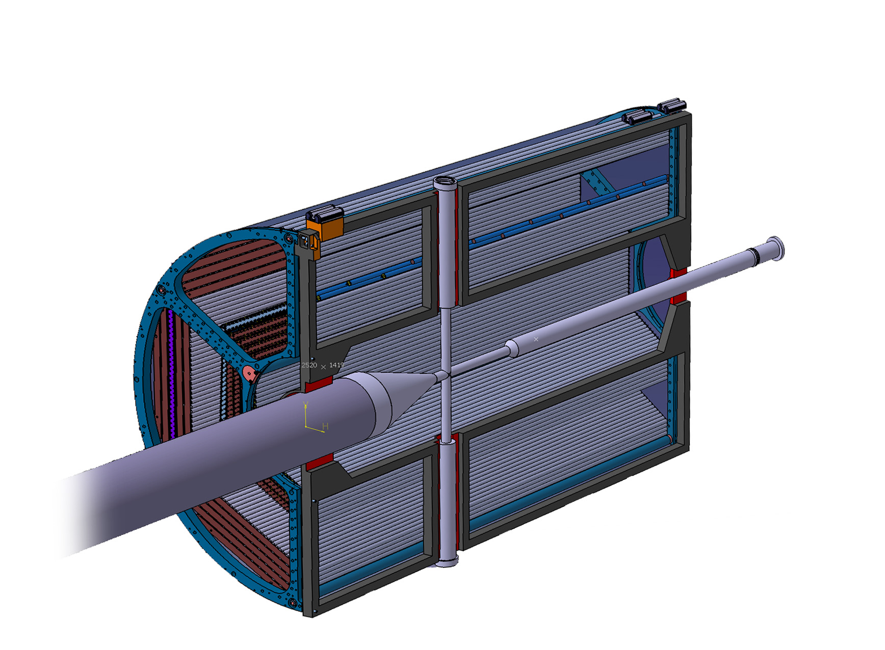
The PANDA detector, shown in Fig. 2 and described in detail in Ref. [25], comprises two parts: the target spectrometer (TS), covering polar angles above in the horizontal direction and in the vertical direction, and the forward spectrometer (FS), covering angles below . The TS consists of the silicon Micro Vertex Detector (MVD), the gas-filled Straw Tube Tracker (STT), the gas electron multiplier detectors (GEM), the barrel Time-of-Flight detector (BarrelToF), a Detector of Internally Reflected Cherenkov light (DIRC), a lead-tungstate (PbWO4) Electro Magnetic Calorimeter (EMC) and a muon detector system. A solenoid magnet, providing a field of up to 2.0 Tesla, enables measurements of charged particle momenta.
The FS will include the Forward Tracking Stations (FTS), i.e. six straw tube stations for tracking. In addtion, it will comprise a dipole magnet, a ring imaging Cherenkov counter (RICH) detector, a forward ToF, a Shashlyk electromagnetic calorimeter and a muon range system.
The PANDA luminosity will be measured by a detector (furthest to the right in the figure) [26].

2.1.1 The PANDA Central Tracking System
The central tracking system, at focus in this work, consist of the MVD, STT, and GEM detectors organised according to the layout in Fig. 3. In the following, we will discuss these detectors in more detail.
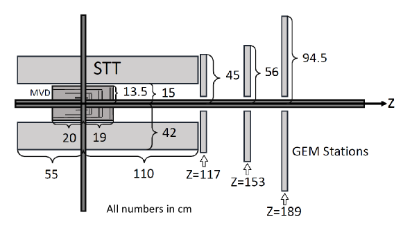
The innermost detector, surrounding the IP, is the Micro Vertex Detector (MVD) [27]. It consists of a barrel part and six disk layers in forward direction along the beam pipe. The purpose of the MVD is to provide hit points for all charged tracks. It will also constrain the origin of tracks from weakly decaying hadrons, e.g. mesons and hyperons. The MVD will cover a radial region up to 13.5 cm, with the innermost and outermost barrel layers located at distances of 2.5 cm and 13.5 cm from the IP, respectively. The polar angle coverage of the MVD is from 3∘ up to 150∘. The MVD utilizes semiconductors in the form of pixels and strips. The barrel part will consist of four layers: the two innermost ones instrumented with pixels and the two outermost layers of rectangular Double Sided Silicon Strip Detectors (DSSD). The forward part comprises six disks with pixel sensors, where the two disks located most downstream along the beam pipe will be equipped with trapezoidal DSSDs. The vertex resolution of the MVD has been found to be of the order of 50 in -direction and -direction and about 100 in -direction [28]. Besides vertex information, the MVD will contribute to particle identification (PID) through energy loss (dE/dx) measurements and also provide time information, with a resolution of about 10 ns.
The Straw Tube Tracker (STT) [29], surrounding the MVD, will be the major component of the central tracking system. Apart from tracking of charged particles, the STT will be used for PID of charged particles with momenta below 1 GeV/c through the energy loss (dE/dx) measurement. The STT will consist of 140 cm long straw tubes, covering a radial distance between 15.0 cm and 41.8 cm and polar angles between 10∘ and 140∘. The straws are made of aluminum-coated mylar tubes with a diameter of 10 mm with a gold-plated tungsten-rhenium anode wire in the center. They will be filled with an Argon-based gas (90) with carbon dioxide as a quench gas (10). About 4,200 drift tubes will be arranged in a closely packed hexagonal pattern as illustrated in Fig. 4. Out of the 27 layers, 15-19 layers will be arranged parallel to the beam axis. This will provide -reconstruction in the -plane, where is the radial position and is the azimuthal angle around the beam axis. The remaining eight central layers are skewed tubes arranged with a stereo angle of relative to the beam axis, enabling the reconstruction of the longitudinal track coordinate [20]. In the -plane, the resolution is 150 m. The longitudinal position resolution is 2-3 mm and the maximum drift-time in the straws is 220 ns.
The transition region between the target and forward spectrometer will be covered by three Gas Electron Multiplier (GEM) stations. These stations, consisting of double-planes, will be located at 117 cm, 153 cm and 189 cm downstream of the IP and have a diameter of 90 cm, 112 cm and 148 cm, respectively. The GEM will cover polar angles between 3∘ and 20∘. Each station will have double-sided readout, meaning that a particle traversing both the front and back of a plane will give rise to two signals.
The tracking of charged particles can be further improved by a precise reference time, , from a fast detector. For this purpose, and for providing PID information, the BarrelToF detector [30] has been designed. It will surround the STT at a radial distance of roughly 50 cm from the beam pipe and cover polar angles between 22∘ and 140∘. The BarrelToF will consist of 1,920 scintillator tiles of size 87.029.45.0 mm3. For particles hitting the centre of a tile, a time resolution of 55.5 ps has been achieved [31].
2.2 Data Readout and Triggering
The PANDA data will be generated and read-out continuously, or free-streaming, and processed to form tracks and clusters which in turn are combined into events. The software trigger then tests whether the events fulfill the requirements of the trigger lines and if this is the case, the event is stored for future analysis. The event building and trigger decisions will be carried out in real time during the operation of the experiment. The required reduction factor of the full trigger stream must be around 1,000, resulting in a maximum event rate of 20 kHz being passed to the permanent storage.
At large beam intensities, subdetector signals from different events will overlap in time. Assuming that the time intervals between interactions are Poisson distributed, the mean time between events at 2 MHz is 500 ns while 20 MHz at 50 ns. Given a maximum STT drift time of 220 ns, the 2 MHz does not lead to much overlap, while 20 MHz does. In the latter case, spatial information alone is not sufficient to reconstruct tracks and events. However, by including time information, signals can be correctly combined using tracking algorithms that are suitable for free-streaming data.
The MVD, GEM and BarrelToF detectors all operate on shorter time scales (between 10 ns and 55 ps) and provide further constraints for track and event building when combining the information with those from the STT.
2.3 The PANDA Software
The simulation studies presented in this work are performed within the framework PandaROOT [32]. The full simulation chain includes Monte Carlo event generation, particle propagation and simulation of the particle’s response, hardware digitization. As further steps, reconstruction and data analysis is performed. The last three steps are common for experimental and simulated data. PandaROOT is derived from the FairROOT framework [33] which in turn is based on ROOT [34].
3 Hyperon Detector Signatures
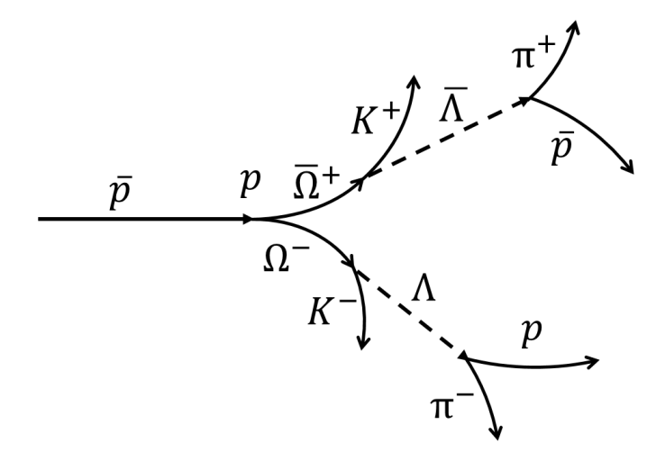
The reaction studied in this work is at beam momenta of GeV/, GeV/, GeV/ and GeV/. The GeV/ and GeV/ points are close to the kinematic threshold – the excess energies are 1.2 MeV and 17.7 MeV, respectively – and therefore represent the low energy extreme. The 5.0 GeV/c point has been studied in some detail while at 4.96 GeV/, only the efficiency has been evaluated. These two points cover the edges of an energy region where interaction studies are possible. The GeV/ point coincides with a planned campaign for measuring the line-shape of (3872) [35], while the GeV/ point is chosen because it is the largest momentum that the HESR will offer. In this sense, it constitutes the high energy extreme of the experiment.
The event topology of this reaction is shown in Fig. 5. The and hyperons decay weakly and hence at a measurable distance from the point of production. Therefore, the full decay topology includes four displaced vertices. The neutral hyperons, represented by dashed lines in the figure, do not interact with the detector material through ionization and can therefore not be tracked. Furthermore, their trajectories do not bend in the magnetic field. The and are charged, their trajectories bend in the magnetic field and they decay sequentially, i.e. to intermediate and , which in turn decay into and , respectively. An isotropic distribution is used for all decays because all valence quarks are annihilated and with increasing number of annihilated s quarks the angular distribution gets more isostropic.
3.1 Simulation Conditions
The following simplifications have been made for the simulations and reconstruction:
100 efficient tracking: An algorithm is used, where detector hits corresponding to those from an original true Monte Carlo track, are grouped together into a reconstructed track.
100 efficient PID: For the purpose of this study, other effects than those of detector hits should be minimized. Ideal PID, where each track is matched with the true Monte Carlo track, is therefore used.
Point-like target: In the real experiment, both the cluster jet target and the pellet target will give rise to residual gas in the beam pipe. This will lead to gas particles outside of the interaction point acting as an effective target in the beam pipe close to the target region. In the simulations presented here, this effect has not been taken into account but instead, a point-like target is simulated. A study of the effect of a more realistic target has been carried out [36]. The preliminary results reveal no significant difference in the reconstruction efficiencies between the ideal and realistic gas in the target for hyperon events originating from beam-target interactions.
3.2 Quantities of Interest
In order to formulate criteria for software trigger lines, data reconstruction algorithms or analysis methods, we have identified quantities on the basis of the detector signatures of a given reaction. These quantities can also give an in-depth understanding of the feasibility of studying a given reaction at a given experiment. The quantities of interest are:
-
1.
Kinematic distributions
-
2.
Decay vertex position
-
3.
Tracking detector hits
-
4.
Detector hits for time information
-
5.
Track efficiency
In the following, we will discuss these quantities in some detail.
3.2.1 Kinematic distributions
The momentum of each particle in the laboratory system versus the laboratory polar angle , defined with respect to the beam axis, provides a first estimate the acceptance of different subdetectors. It also reveals how well the final state particles can be separated kinematically. In addition, the transverse momentum [GeV/c] is of relevance because in the TS solenoid field [T], charged particles will follow helix trajectories with radius
| (1) |
Here, the charge, [C], determines the rotational direction of the trajectory. This means that particles produced at the IP with a transverse momentum smaller than 270 MeV/c will be trapped in a spiral trajectory inside the STT. These particles will not give rise to signals in detectors outside the STT such as the BarrelToF. Particles from displaced decay vertices can however reach outside of the STT even at smaller transverse momenta.
3.2.2 Decay vertex position
The decay vertex position longitudinal () and transversal () to the beam indicate in which detectors we expect signals from the decay products.
3.2.3 Tracking detector hits
Whether a particle will give rise to signals from which a complete track can be reconstructed, depends on the number of hits in the main tracking detectors. In the TS, the STT and the GEM are the relevant systems and in the FS it is the FTS. We define three main categories:
-
1.
A particle gives rise to sufficiently many hits to form a reconstructable track ( 4 STT hits)
-
2.
A particle gives rise to too few hits to be reconstructable (0-3 STT hits)
-
3.
A particle gives rise to a very large number of hits ( 50 STT hits)
3.2.4 Detector hits for time information
Straw tube trackers such as the STT and the FTS rely on a precise reference time, , to extract the drift time and thereby precisely determine the particle trajectory. The barrel and forward ToF are sufficiently fast to provide such time-stamps. Events without timestamps from these, can instead use information from the MVD or GEM for this purpose. At low luminosities, where the signals from different events will be fairly well separated in time, it will be sufficient to use one particle per event for a reasonable estimate of . This is referred to as events with hits.
However, at higher luminosities, signals from different events will overlap in time. Therefore, a hit in a fast detector needs to be combined with hits from the same particle in the tracking detectors. That requires that each particle has a precise time-stamp, i.e. that each track has a corresponding hit in the MVD, GEM or Barrel ToF. This we refer to as tracks with hits.
3.2.5 Track efficiency
A reconstructable track has a reasonable chance to be correctly reconstructed by the pattern recognition algorithm in the TS if it contains at least four MVD hits or at least six hits in the MVD+STT+GEM and at least four STT hits.
In order to reconstruct the reaction exclusively, all final state tracks need to be reconstructed. To determine the efficiency, we take the full PANDA detector into account, i.e. the TS and the FS. The efficiency is defined as the fraction of events where all final state particles give rise to reconstructable tracks with at least four MVD or six MVD+STT+GEM hits or six hits in forward tracker planes.
4 Results
4.1 Kinematic distributions
The lab momentum versus the lab polar angle distribution is shown for all involved particles in Fig. 6. As expected, light particles are generally emitted at larger angles and smaller momenta than heavier particles. At a beam momentum of 5.0 GeV/c, the distributions from pions, kaons and protons/antiprotons are fairly well separated in contrast to larger beam momenta.
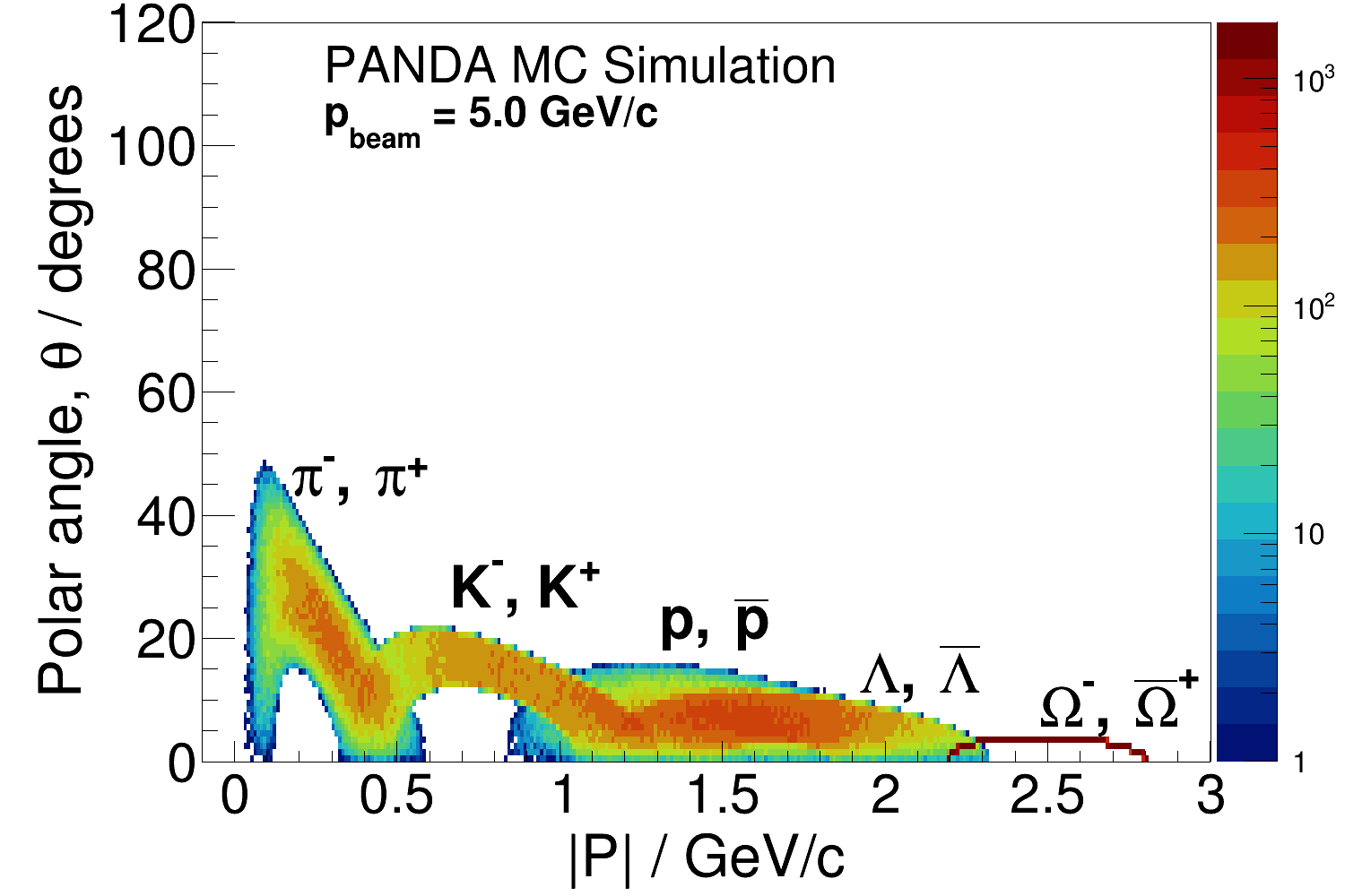
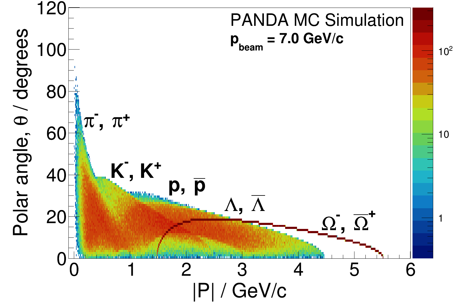
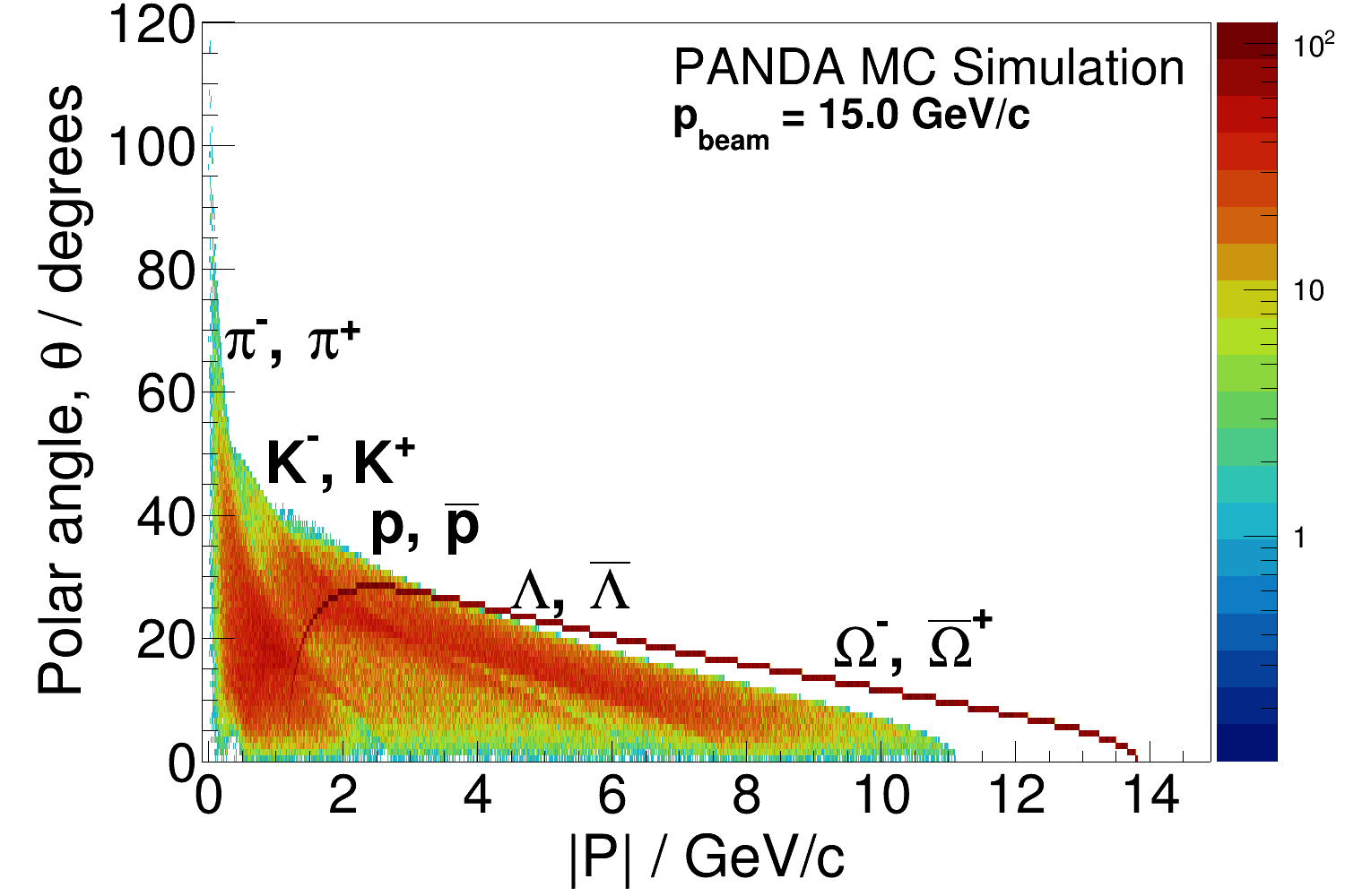
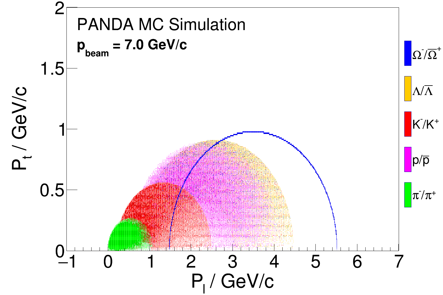
Fig. 7 displays the transverse versus the longitudinal momentum distribution of the final state and intermediate particles. At a beam momentum of 5.0 and 7.0 GeV/c most pions have small transverse momenta. However, since they come from a displaced hyperon decay vertex, there is a possibility that they leave the STT.


4.2 Decay Vertex Distribution
The decay vertex distributions of the and hyperons are shown in Fig. 8 and also summarized in Table 1. We conclude that most decays occur inside the MVD at all beam momenta, which means that the kaons give rise to signals in the MVD. Also the daughter decay to a large extent within the MVD. However, at larger beam momenta, the probability for the decay to occur between the MVD and the GEM planes increases. The decay products are then expected to leave hits in the STT, GEM or the FS.
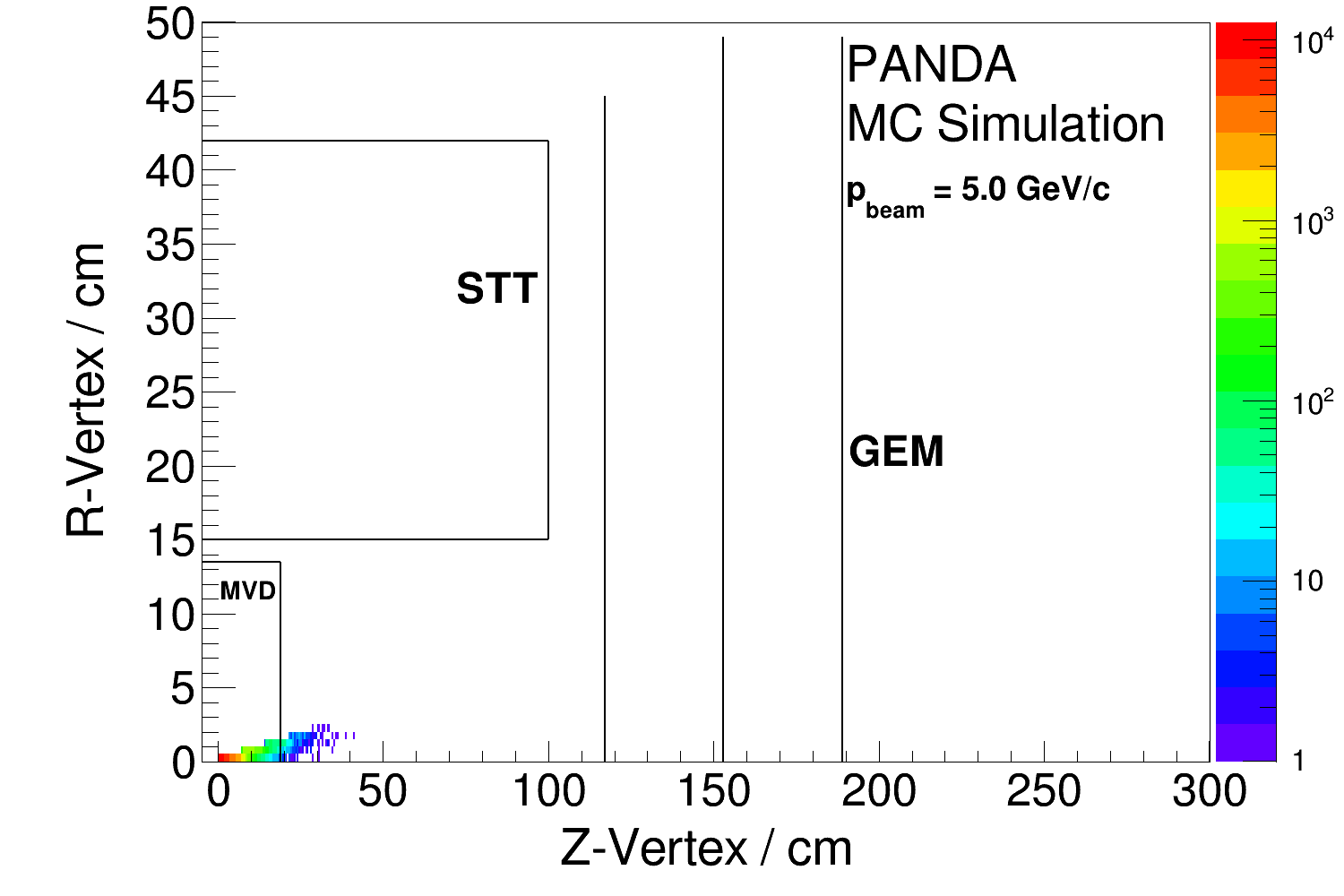
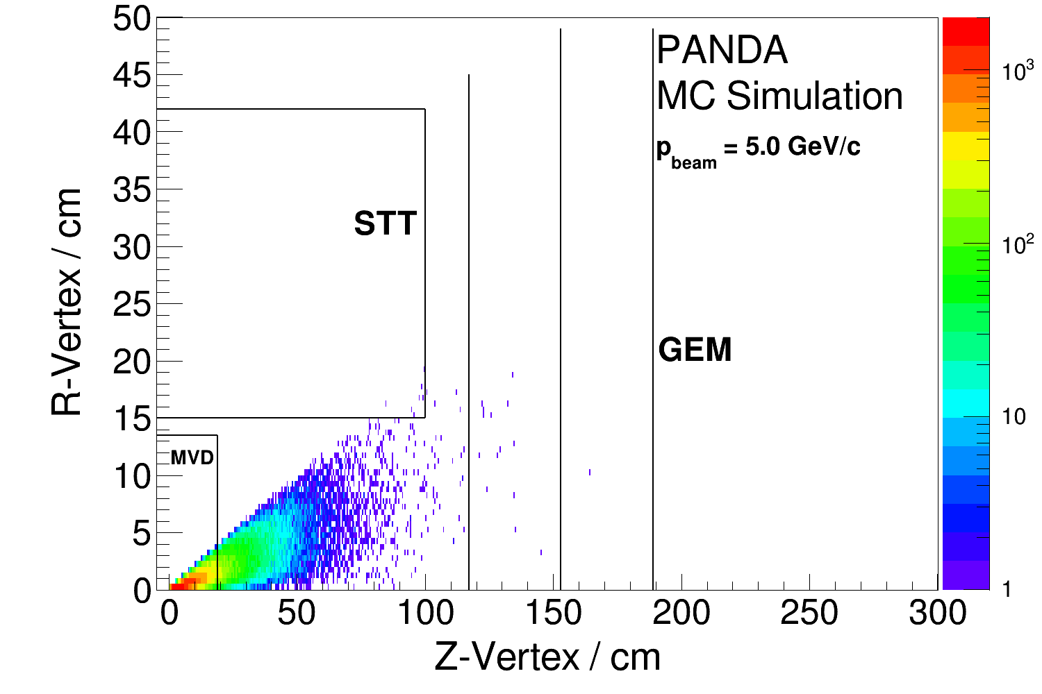
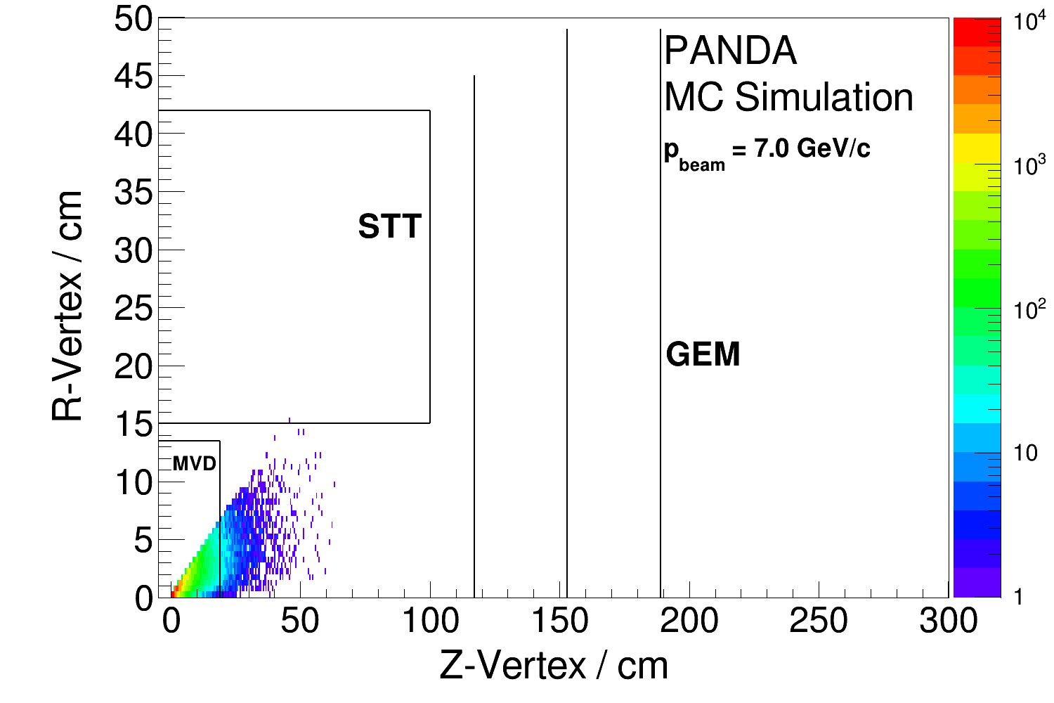
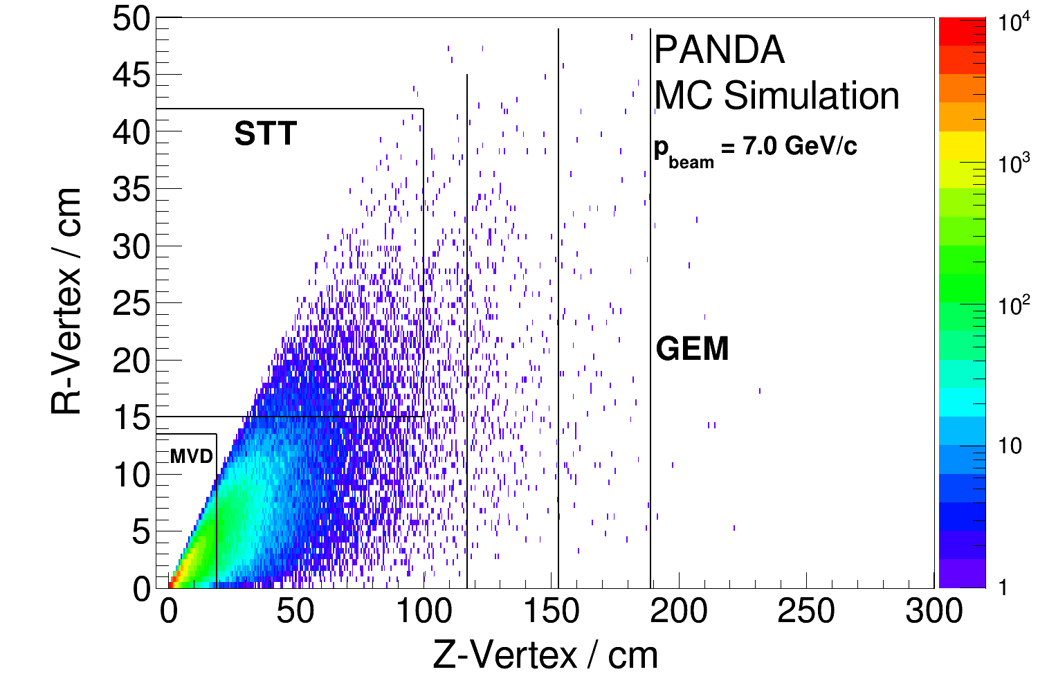
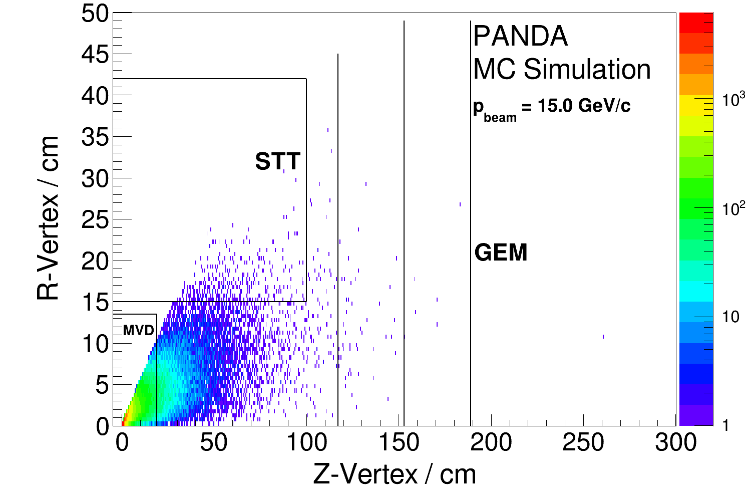
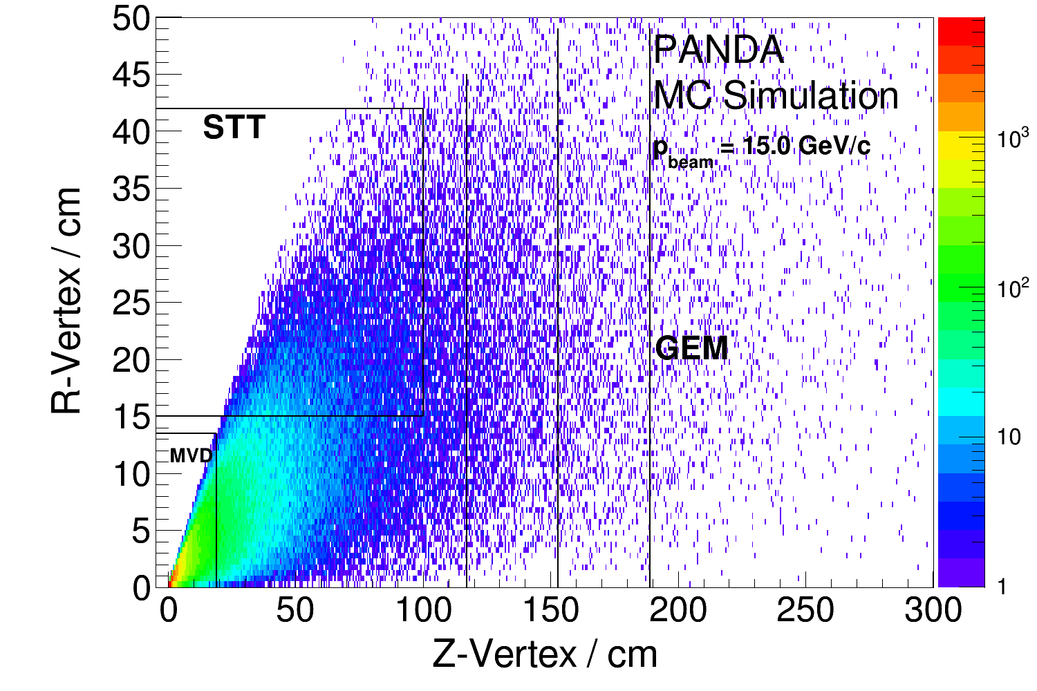
| and | 5.0 GeV/c | 7.0 GeV/c | 15 GeV/c |
|---|---|---|---|
| MVD | 99.3% | 96.7% | 82.2% |
| STT | 0% | 0.001% | 0.37% |
| TS acceptance | 100% | 100% | 99.9% |
| and | |||
| MVD | 70.9% | 57.4% | 32.3% |
| STT | 0.009% | 3.41% | 15.9% |
| TS acceptance | 99.97% | 99.3% | 90.5% |
4.3 Reconstructable tracks
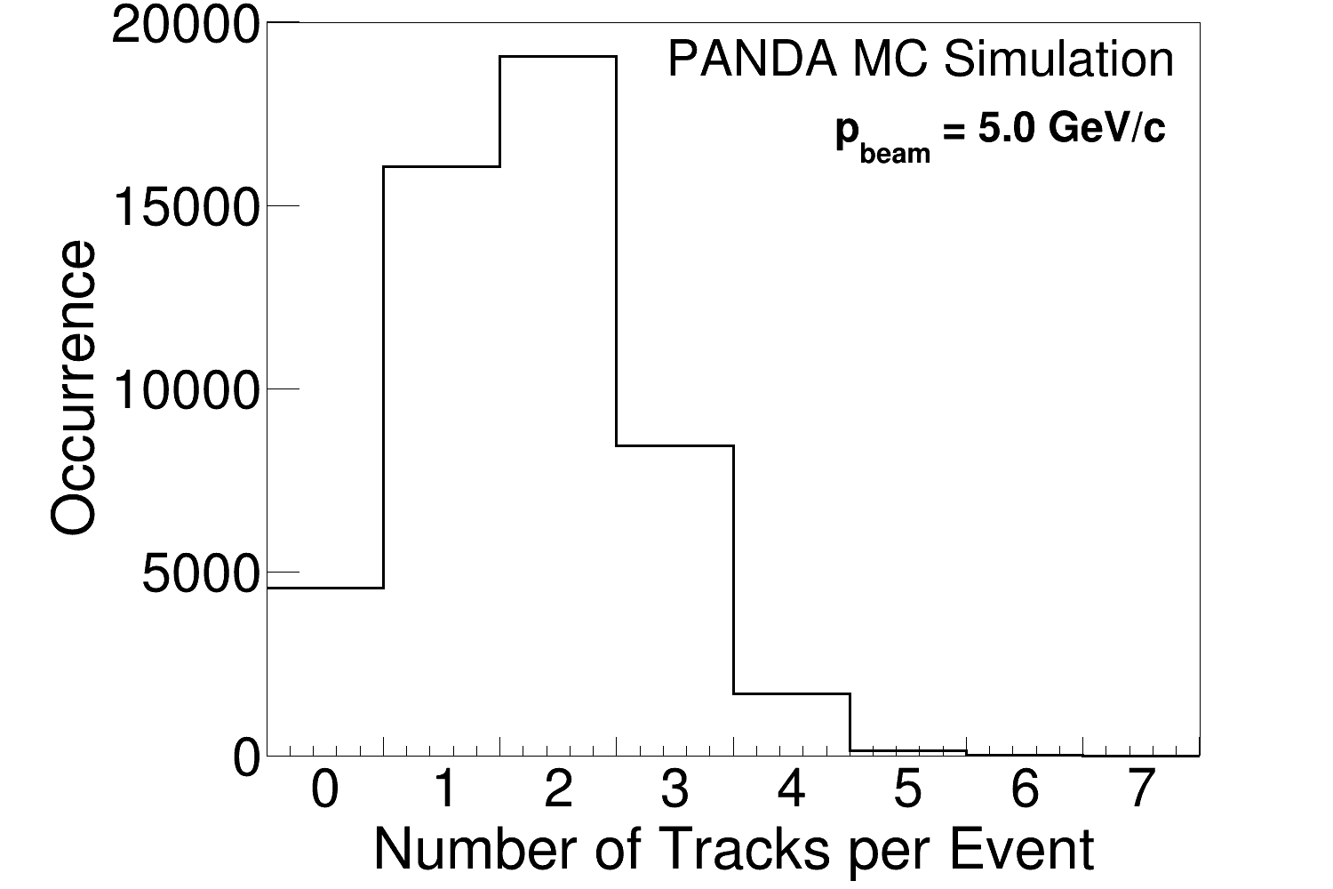
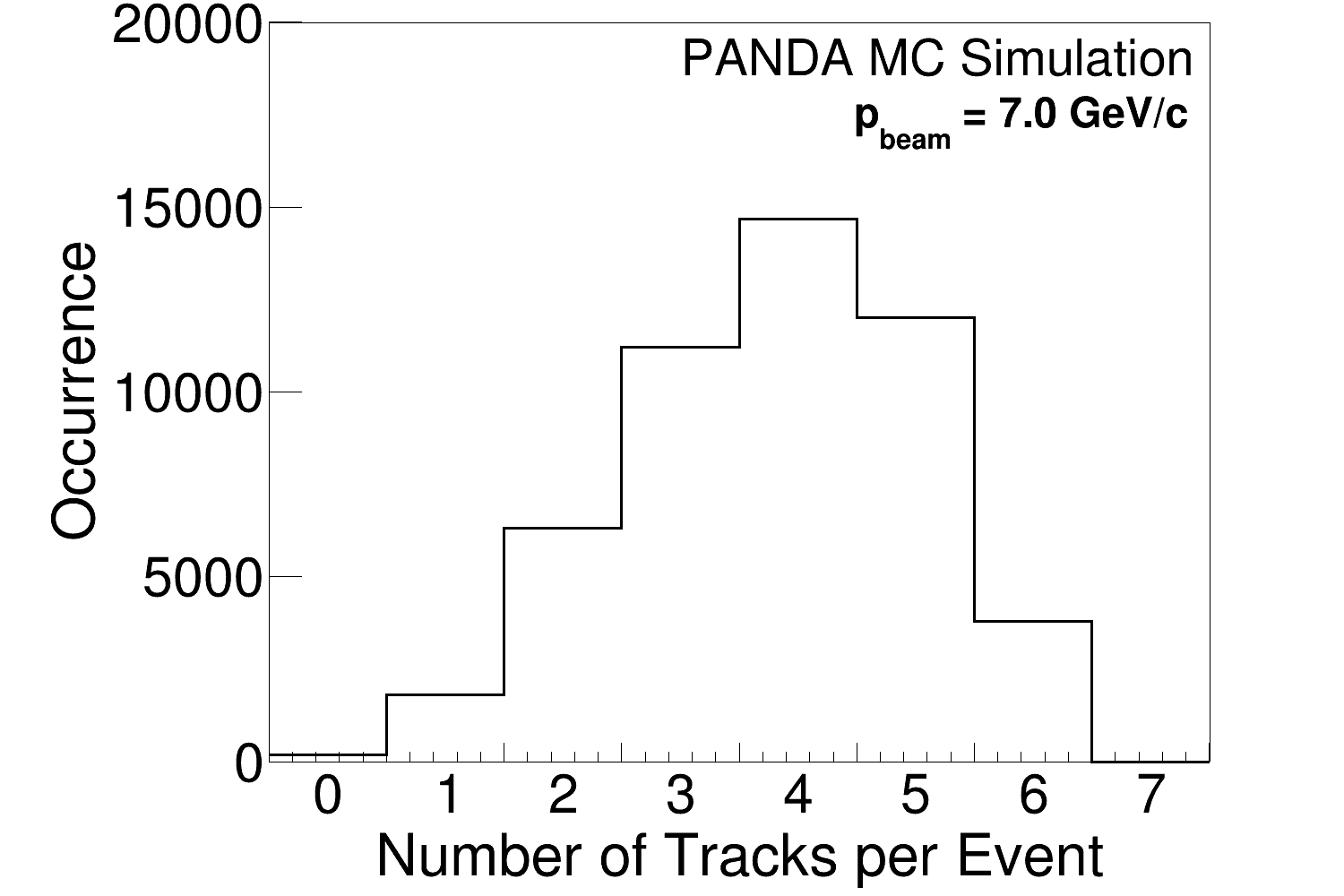
The fraction of events where a given final state particle gives rise to a reconstructable track is shown in Table 2. At all beam momenta, most final state particles are reconstructable in the TS. Many of the remaining particles may be reconstructable in the FS, as we will come back to in section 4.6.
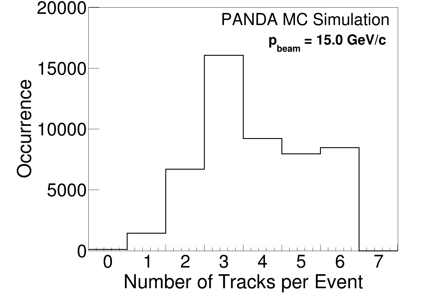
The number of reconstructable tracks per event in the TS are shown in Fig. 9. At 5.0 GeV/c, about two TS tracks are reconstructed per event while at larger beam momenta, most event contain more three or more reconstructable TS tracks.
| Particle | 5.0 GeV/c | 7.0 GeV/c | 15.0 GeV/c |
|---|---|---|---|
| 76% | 67% | 64% | |
| 76% | 66% | 64% | |
| 79% | 59% | 64% | |
| 80% | 61% | 66% | |
| 80% | 63% | 61% | |
| 81% | 63% | 62% |
4.4 Tracking detector hits
The tracking of decay products originating from inside the STT rely on STT-based algorithms e.g. those described in Ref. [20]. The same is true for particles originating from the area between the MVD and the first GEM station, provided they are emitted in the direction of the STT. The transverse momentum components and are obtained from a preliminary track fit, which requires at least three hits. However, requiring at least four hits in the STT gives a more accurate fit. From Table 3, we conclude that at 7.0 and 15.0 GeV/c, most particles emitted within the TS acceptance (first row) give rise to 4 STT hits or more (second row).
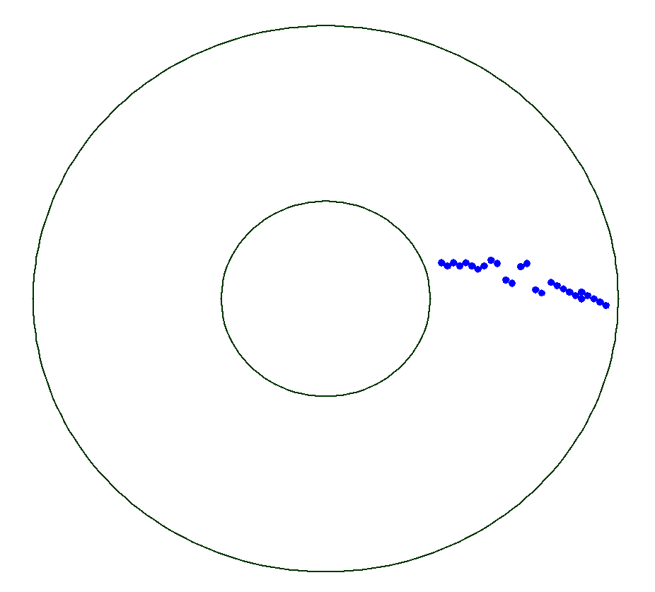
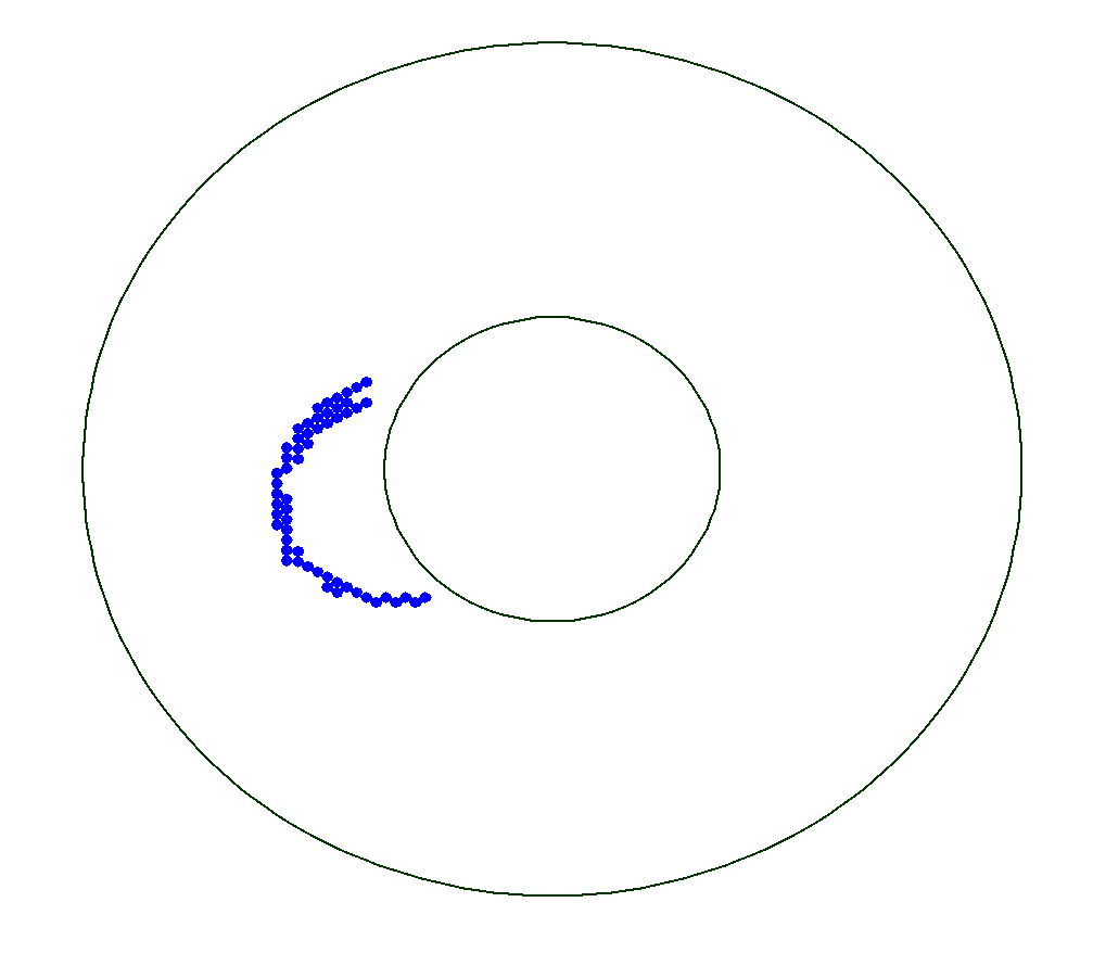
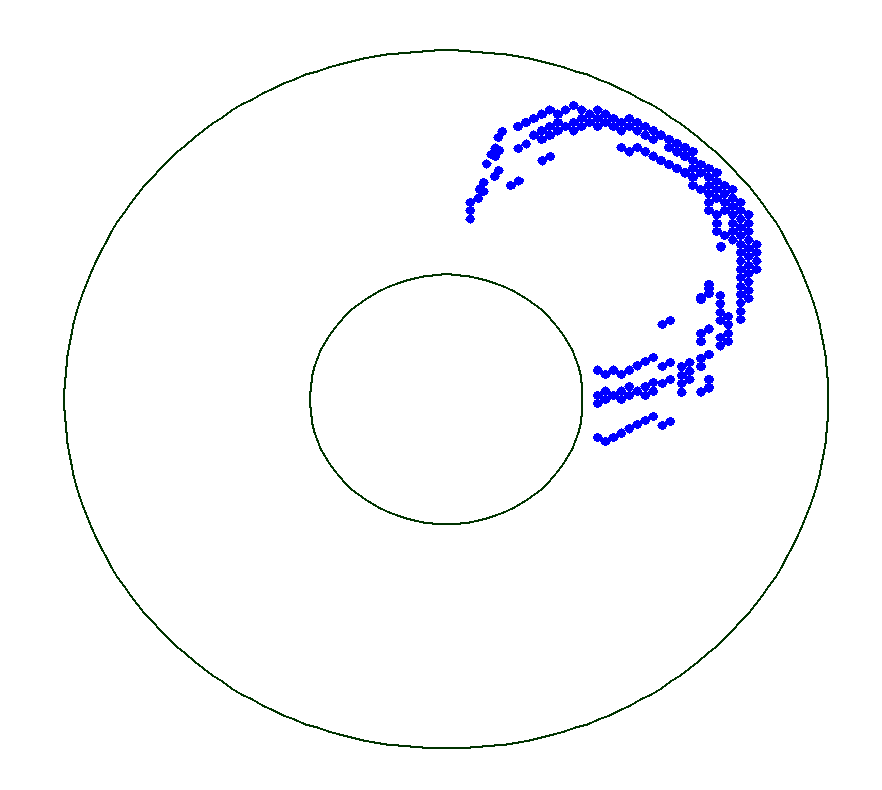
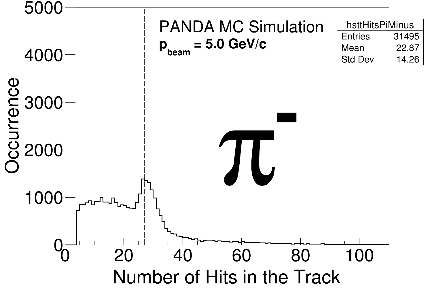
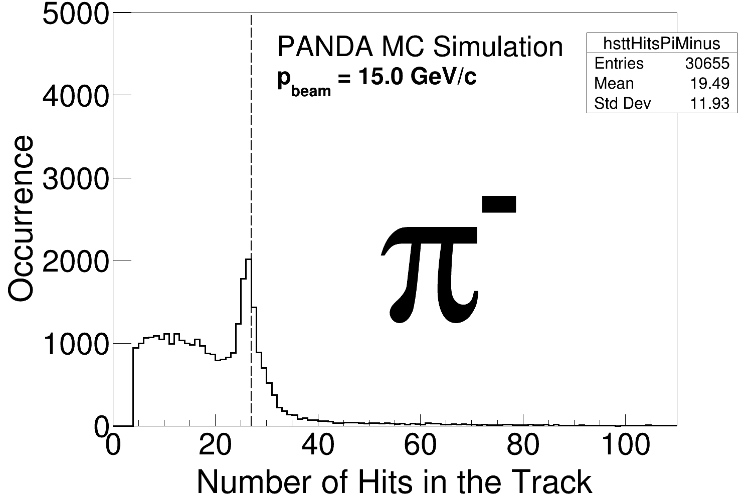
The ideal STT hit pattern to fit is when a particle traverses the full STT in radial direction and leaves a hit in each of the 27 layers. This is illustrated in the left panel of Fig. 10. Particles with small transverse momenta, which we know from Fig. 6- 7 are primarily pions, could however get trapped in the solenoid field where they lose energy ( 10 keV/cm) through interactions with the gas and tube walls in the STT. As a consequence, these pions will move in spiral trajectories and hence give rise to a very large number of hits. This is illustrated in the middle and right panels of Fig. 10. Pions making a full turn or more, hence leaving 50 hits in the STT, are difficult to reconstruct with common algorithms. In Fig. 11, the hit pattern for pions is shown. At 7.0 and 15.0 GeV/c, the STT hit distribution features a clear peak around 27 hits which corresponds to pions traversing the full STT. However, at 5.0 GeV/c, no such peak is seen which means that many of these pions are either stopped or trapped within the STT. However, we see in Table 3 that the number of events with pions leaving more than 50 hits is lower than 1.1.
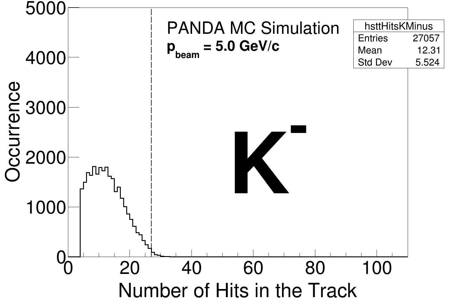
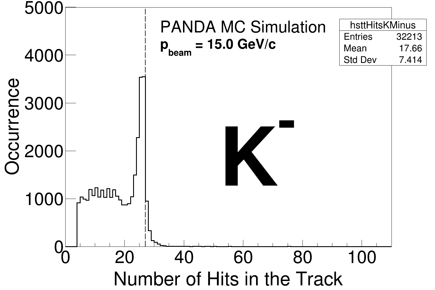
In Fig. 12, the hit pattern from the kaons is shown. The clearly discernible peaks around 27 hits at the 7.0 GeV/c and 15.0 GeV/c show that many kaons traverse the full STT detector at these beam momenta.


| STT hits / track | 5.0 GeV/c | 7.0 GeV/c | 15.0 GeV/c |
|---|---|---|---|
| 4 | 43 | 63 | 64 |
| 50 | 0.7 | 1.1% | 0.6 |
4.5 Detector hits for time information
The number of events containing at least one signal from either the MVD, the GEM or the BarrelToF is shown in Table 4. In almost all events, there is a signal in either the MVD or the GEM, or both. Furthermore, many events also contain at least one hit in the dedicated timing detector, i.e. the BarrelToF. We conclude that a time-stamp can be obtained from either the MVD, the GEM or the BarrelToF in practically all events.
| Detector | 5.0 GeV/c | 7.0 GeV/c | 15.0 GeV/c |
|---|---|---|---|
| MVD | 99.5% | 99.6% | 97.5% |
| GEM | 99.9% | 99.8% | 97.8% |
| BarrelToF | 0.6% | 40.0% | 57.3% |
Table 5 displays the fraction of the reconstructable tracks in the TS that have associated hits in fast BarrelToF, MVD or GEM detectors. This is crucial at higher luminosities, since it will then be necessary to associate each track segment with a reference time. Indeed, in most events, the tracks include hits from at least one of the fast detectors.
| Detector | 5.0 GeV/c | 7.0 GeV/c | 15.0 GeV/c |
|---|---|---|---|
| MVD | 86% | 74% | 59% |
| GEM | 87% | 63% | 51% |
| MVD or GEM | 99% | 93% | 84% |
| BarrelToF | 0.2% | 11% | 20% |
| BarrelToF or MVD | 86% | 76% | 64% |
| BarrelToF or MVD or GEM | 99% | 94% | 89% |
| Fraction of all generated tracks (in TS) | 43% | 63% | 64 |
4.6 Track efficiency
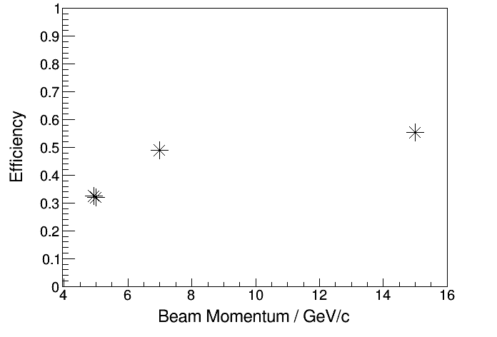
In this first feasibility study of the reaction with PANDA, the track efficiency in the TS and the FS was determined. The criterion for track reconstructability in the FS is at least six hits in the FTS planes. In addition to measure the number of final state particles (pions, kaons and protons/antiprotons), we also combine pions and protons (antiproton) into () candidates as well as kaons and () into () candidates. Finally, we calculate the number of event where we have a pair of an and an candidate. The results are presented in Table 6. The number of generated events, 50,000, are used for normalization. The final efficiency is presented in Fig. 13 and Table 6. It is found to be larger than 30% at all studied beam momenta, even very close to the kinematic threshold. The main variation with respect to the beam momentum is associated with the kaon reconstruction.
| Particle | 4.94 GeV/c | 5.0 GeV/c | 7.0 GeV/c | 15.0 GeV/c |
|---|---|---|---|---|
| 87 | 87 | 92 | 88 | |
| 83 | 84 | 91 | 87 | |
| 80 | 80 | 87 | 90 | |
| 82 | 82 | 88 | 91 | |
| 82 | 82 | 87 | 86 | |
| 83 | 83 | 86 | 87 | |
| 72 | 72 | 80 | 81 | |
| 69 | 69 | 79 | 80 | |
| 57 | 57 | 70 | 73 | |
| 57 | 56 | 70 | 74 | |
| 33 | 32 | 49 | 55 |
5 Summary and Outlook
We have studied the reaction and its subsequent decays in the PANDA detector, with focus on the TS. By studying hit patterns in tracking detectors and hits in fast detectors, we achieve a detailed understanding of the reconstruction feasibility of this reaction. This is crucial when developing track reconstruction and when outlining a strategy for event building and triggering.
From the studied quantities we can formulate criteria in terms of particle kinematics, decay vertex positions, hits from detectors providing tracking and time information, and track efficiency. Our results demonstrate the importance of the MVD and GEM detectors for time-stamps; these detectors are hit in at least 97.5 of the events. The STT detector is crucial in the tracking of hyperon decay products since more than 43 of all tracks contain at least four STT hits.
The track efficiency of the PANDA detector (TS + FS) was determined from the acceptance in simulations and was found to increase from about 30% close to threshold to about 50% at larger beam momenta. This indicates a good feasibility for studies of the . The final efficiency will however be lower, after taking finite trigger- detector and reconstruction efficiencies into account.
Finally, our study provides guidance in how to exploit the hyperon detector signatures in the software trigger and event building scheme:
-
1.
Kaons from the decays can be reconstructed using a primary track finder, i.e. an algorithm that uses the constraint that the track originates from the interaction point, combining information from the MVD and the STT.
-
2.
The hyperons must be reconstructed in the STT or the FTS utilizing a secondary track finder.
-
3.
At least three reconstructed TS tracks are required in each event.
-
4.
Up to four displaced decay vertices in the MVD, the STT or in the FS are required in each event.
-
5.
The of TS tracks are obtained from the MVD, GEM or BarrelToF detectors.
These studies demonstrates the potential of a program of pioneering studies of the production and decay of hyperons, and demonstrates the versatility and good performance of the PANDA detector.
6 Acknowledgements
We acknowledge financial support from
the Bhabha Atomic Research Centre (BARC) and the Indian Institute of Technology Bombay, India;
the Bundesministerium für Bildung und Forschung (BMBF), Germany;
the Carl-Zeiss-Stiftung 21-0563-2.8/122/1 and 21-0563-2.8/131/1, Mainz, Germany;
the Center for Advanced Radiation Technology (KVI-CART), Groningen, Netherlands;
the CNRS/IN2P3 and the Université Paris-Sud, France;
the CU (Czech Republic): MSMT LM2018112, OP VVV CZ.02.1.01/0.0/0.0/18_046/0016066;
the Deutsche Forschungsgemeinschaft (DFG), Germany;
the Deutscher Akademischer Austauschdienst (DAAD), Germany;
the European Union’s Horizon 2020 research and innovation programme under grant agreement No 824093;
the Forschungszentrum Jülich, Germany;
the Gesellschaft für Schwerionenforschung GmbH (GSI), Darmstadt, Germany;
the Helmholtz-Gemeinschaft Deutscher Forschungszentren (HGF), Germany;
the INTAS, European Commission funding;
the Institute of High Energy Physics (IHEP) and the Chinese Academy of Sciences, Beijing, China;
the Istituto Nazionale di Fisica Nucleare (INFN), Italy;
the Ministerio de Educación y Ciencia (MEC) under grant FPA2006-12120-C03-02, Spain;
the Polish Ministry of Science and Higher Education (MNiSW) grant No. 2593/7, PR UE/2012/2, and the National Science Centre (NCN) DEC-2013/09/N/ST2/02180, Poland;
the Schweizerischer Nationalfonds zur Förderung der Wissenschaftlichen Forschung (SNF), Switzerland;
the Science and Technology Facilities Council (STFC), British funding agency, Great Britain;
the Scientific and Technological Research Council of Turkey (TUBITAK) under the Grant No. 119F094, Turkey;
the Stefan Meyer Institut für Subatomare Physik and the Österreichische Akademie der Wissenschaften, Wien, Austria;
the Swedish Research Council and the Knut and Alice Wallenberg Foundation, Sweden;
the U.S. Department of Energy, Office of Science, Office of Nuclear Physics;
The results published in this article have been obtained in collaborative
efforts before 24.02.2022 and are thus signed by the full collaboration
including scientists from Russian and Belarus institutions.
References
- [1] M. Ablikim et al., (BESIII Collaboration) Phys. Rev. Lett. 123, 122003 (2019).
- [2] M. Ablikim et al. (BESIII Collaboration), Nature Phys. 15, p. 631–634 (2019).
- [3] D. G. Ireland et al., (CLAS Collaboration) Phys. Rev. Lett. 123, 182301 (2019).
- [4] J. Adamczewski-Musch et al., (HADES and PANDA@HADES Collaborations), Eur.Phys.J. A 57, 4, 138 (2021).
- [5] W. Erni et al. (PANDA collaboration), Strong Interaction Studies with PANDA, Physics Performance Report (2009) arXiv[hep-ex]:0903.3905.
- [6] G. Barucca et al., (PANDA Collaboration), Eur.Phys.J. A 57, 4, 154 (2021).
- [7] G. Barucca et al., (PANDA Collaboration), Eur.Phys.J. A 57, 4, 184 (2021). https://doi.org/10.1140/epja/s10050-021-00475-y
- [8] G. Barucca et al., (PANDA Collaboration), Eur.Phys.J. A 57, 4, 149 (2021). https://doi.org/10.1140/epja/s10050-021-00444-5
- [9] B. Singh et al., (PANDA Collaboration), Nucl.Phys. A 954, 323-340 (2016). https://doi.org/10.1016/j.nuclphysa.2016.05.014
- [10] V. E. Barnes et al. Phys. Rev. Lett. 12 (8): 204 (1964). https://doi.org/10.1103/PhysRevLett.12.204
- [11] M. Gell-Mann, The Eightfold Way: A Theory of strong interaction symmetry, DOI:10.2172/4008239 (1961); Y. Ne’eman, Nucl. Phys. 26, 2, p222-229 (1961).
- [12] A. B. Kaidalov and P. E. Z. Volkovitsky, Phys. C 63 51 (1994).
- [13] E. Perotti, J.Phys.Conf.Ser. 1024, 1, 012019 (2018).
- [14] E. Perotti et al., Phys. Rev. D 99, 056008 (2019).
- [15] J. Haidenbauer and U.-G. Meissner, Phys. Lett. B 761, 456-461 (2016).
- [16] D. Lonardoni et al., Phys. Rev. Lett. 114, 092301 (2015).
- [17] M. Ablikim et al., (BESIII Collaboration), Phys. Rev. Lett. 126, 9, 092002 (2021).
- [18] R.L. Workman et al. (Particle Data Group), Prog. Theor. Exp. Phys. 2022, 083C01 (2022).
- [19] W. Ikegami Andersson, Exploring the Merits and Challenges of Hyperon Physics with PANDA at FAIR, PhD Thesis, Uppsala Universitet (2020). urn:nbn:se:uu:diva-401856
- [20] W. Ikegami Andersson et al., Computing and Software for Big Science 5, 18 (2021).
- [21] J. Regina Track Reconstruction on Free-Streaming Data for PANDA at FAIR, Conference Proceedings, Connecting the Dots 2020, Available at Zenodo at CERNs Data Centre, Page 85-92
- [22] M. Durante et al., Physica Scripta 94, 033001 (2019).
- [23] R. Maier et al., HESR Technical Design Report V. 3.1.2 (2008).
- [24] A. Khoukaz et al., The PANDA Internal Targets, Technical Design Report (2012).
- [25] The PANDA Collaboration, PANDA Technical Progress Report, FAIR-ESAC (2005). https://panda.gsi.de/oldwww/archive/public/pandatpr.pdf
- [26] M. Fritsch et al., The PANDA Luminosity Detector, Technical Design Report (2018).
- [27] PANDA Collaboration, Strong Interaction Studies with Antiprotons, Technical Design Report for the: PANDA Micro Vertex Detector (2012).
- [28] R. Kliemt, Simulations with the PANDA Micro-Vertex-Detector, PhD-Thesis, Helmholtz-Institut fr Strahlen- und Kernphysik der Rheinischen Friedrich-Wilhelms-Universität, Bonn (2013).
- [29] PANDA Collaboration, Strong Interaction Studies with Antiprotons, Technical Design Report for the: PANDA Straw Tube Tracker, Eur. Phys. J. A (2013) 49: 25
- [30] PANDA Collaboration, Technical Design Report for the: PANDA Barrel Time-of-Flight (2016).
- [31] S. Zimmermann, The PANDA Barrel-TOF Detector, Presentation, INSTR-17 - Novosibirsk Russia, (2017). https://indico.inp.nsk.su/event/8/sessions/197/20170302
- [32] S. Spataro and the PANDA collaboration, The PandaRoot framework for simulation, reconstruction and analysis, J.Phys.: Conf. Ser. 331 (2011) 032031.
- [33] M. Al-Turany et al. The FairRoot Framework, J.Phys.: Conf. Ser. 396.2 (2012) 022048.
- [34] A. Naumann, ROOT - A C++ framework for petabyte data storage, statistical analysis and visualization, Computer Physics Communications 180 2499-2512 (2009).
- [35] G. Barucca et al., (PANDA Collaboration) Eur. Phys. J. A 55, 42 (2019).
- [36] A. Akram, Towards Realistic Hyperon Reconstruction in PANDA: From Tracking with Machine Learning to Interactions with Residual Gas, PhD Thesis, Uppsala Universitet (2023).