Vol.0 (2023) No.0, 000–000
22institutetext: Guizhou Radio Astronomical Observatory, Guizhou University, Guiyang 550000, China
33institutetext: College of Earth Sciences, Guilin University of Technology, Guilin 541004, China
Performance of FAST with an Ultra-Wide Bandwidth Receiver at 500-3300 MHz
Abstract
The Five-hundred-meter Aperture Spherical radio Telescope (FAST) has been running for several years. A new Ultra-Wide Bandwidth (UWB) receiver, simultaneously covering 500-3300 MHz, has been mounted in the FAST feed cabin and passed a series of observational tests. The whole UWB band is separated into four independent bands. Each band has 1048576 channels in total, resulted in a spectral resolution of 1 kHz. At 500-3300 MHz, the antenna gain is around 14.3-7.7 K Jy-1, the aperture efficiency is around 0.56-0.30, the system temperature is around 88-130 K, and the HPBW is around 7.6-1.6 arcmin. The measured standard deviation of pointing accuracy is better than 7.9 arcsec, when zenith angle (ZA) is within 26.4∘. The sensitivity and stability of the UWB receiver are confirmed to satisfy expectation by spectral observations, e.g., H I and OH. The FAST UWB receiver already has a good performance for taking sensitive observations in various scientific goals.
keywords:
instrumentation: detectors — radio telescope: FAST — line: profiles1 Introduction
The Five-hundred-meter Aperture Spherical radio Telescope (FAST) with an effective diameter of 300 m has obtained many groundbreaking achievements, for example in observations of pulsar, fast radio burst, star formation, galaxy evolution (e.g., Cheng et al., 2020; Han et al., 2021; Li et al., 2021; Niu et al., 2022; Ching et al., 2022; Xu et al., 2022), since FAST began its commission when the construction was completed on September 25, 2016 (Nan et al., 2011; Jiang et al., 2019, 2020). Till now, FAST mainly worked at frequencies of 1000-1500 MHz with a 19-beam receiver. Recently, a new cryogenic UWB receiver at 500-3300 MHz has been developed by Liu et al. (2022) and mounted in the FAST feed cabin for science observations. In view of the 19-beam receiver occupies all three Hellium cryogenic compressors and most of the space of the feed cabin, currently it has no enough space for the UWB receiver to place any more cryogenic compressor. Now, the FAST UWB receiver has passed a series of test work, and could be carried out kinds of spectral observations.
At 500-3300 MHz, the FAST UWB receiver is ideally able to simultaneously cover 330 radio combination lines (RRLs) for H, He, and C (), respectively. This could help us to investigate the active star formation regions in the Milky Way (e.g., Chen et al., 2020; Zhang et al., 2021; Hou et al., 2022). Furthermore, the UWB receiver could simultaneously cover the Hydrogen (H I at 1420.406 MHz) and Hydroxyl radical (OH at 1612.231, 1665.402, 1667.359, and 1720.530 MHz) lines, and also their high redshift signals with . This gives us an opportunity to study the star formation and evolution not only in the Milky way, but also in the nearby galaxies especially to provide us with multiwavelength spectral data. In addition, the UWB receiver has been able to catch the Methyladyne (CH) line at 3263.794 MHz. This would return us a high spatial resolution data (1.6′) for better inspecting our Galaxy. Furthermore, the UWB receiver has a sufficient sensitivity and high enough spectral resolution (1 kHz). This allows us to well study the kinematic information of star formation in the Milky Way and the hyperfine structures of some spectral lines (e.g., OH at 1665.402 MHz).
Thanks to the advantageous characteristics of the FAST, we are able to complete a series of observational tests in a short time. In this report, we mainly present the performance of the FAST UWB receiver and relevant antenna parameters at 500-3300 MHz. General parameters of FAST UWB receiver are listed in Table 1. In Section2, we introduce the measurement parameters of the UWB receiver system including the noise dipole, beam properties, pointing accuracy, antenna gain, aperture efficiency, and system temperature. In Section 3, we present the properties of the spectral backend and the measurement results in spectral H I and OH observations. Summary is presented in Section 4.
| FAST UWB receiver | UWB-1 | UWB-2 | UWB-3 | UWB-4 |
|---|---|---|---|---|
| Total frequency range (MHz) | ||||
| Total channel number | 1048576 | 1048576 | 1048576 | 1048576 |
| Spectral resolution (Hz) | 1049.04 | 1049.04 | 1049.04 | 1049.04 |
| Effective frequency range (MHz) | ||||
| Recommended frequency range (MHz) | ||||
| Central frequency (MHz) | 550 | 1350 | 2150 | 2950 |
| Local oscillator frequency (MHz) | None | 1900 | 2700 | 3500 |
| Beam width HPBW (arcmin) | ||||
| High noise temperature (K) | ||||
| High noise temperature (K) | ||||
| Low noise temperature (K) | ||||
| Low noise temperature (K) | ||||
| Antenna gain (K/Jy) | ||||
| Aperture efficiency | ||||
| System temperature (K) |
Notes. Detailed parameter setups for the UWB receiver are presented in Liu et al. (2022), e.g., the cryogenic microwave unit, the warm microwave, and the frequency mixing unit.
2 Measurement Parameters of the UWB receiver
2.1 The Noise Source
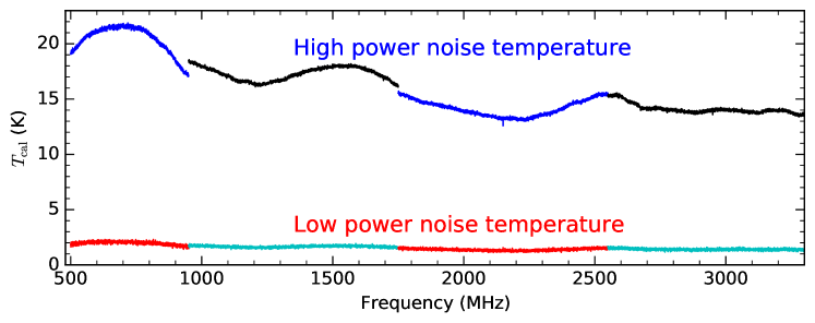
Like FAST 19-beam array, the UWB receiver also contains a stabilized noise injection system (Jiang et al., 2020). The noise is injected between the feed and the low noise amplifiers. The noise source is a single diode whose signal is split into each polarization. The noise diode has two adjustable power output modes with 1.5-2.0 K for low power noise temperature, and 13.5-22.0 K for high power noise temperature. Based on testing a series of hot load measurements, the noise diode is stable and meet the requirements of data calibration. The low and high power noise temperatures are shown in Figure 1 and listed in Table 2. The full noise diode data for UWB 500-3300 MHz could be download online.
2.2 Beam Size
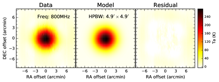
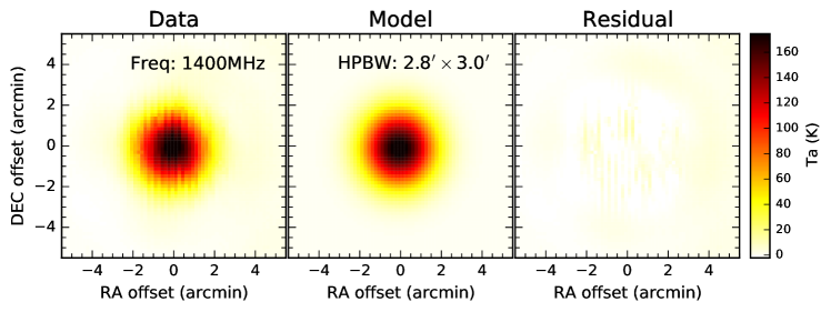
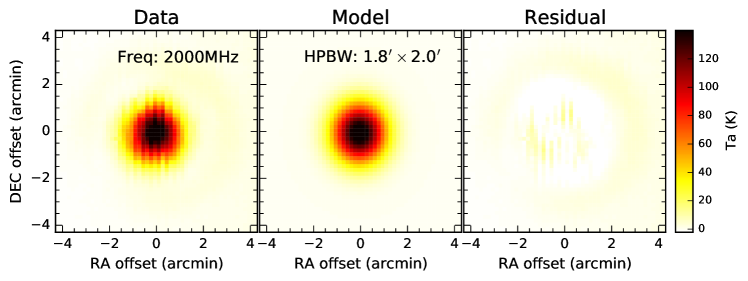
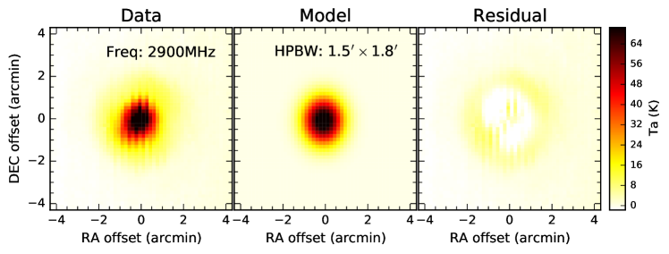
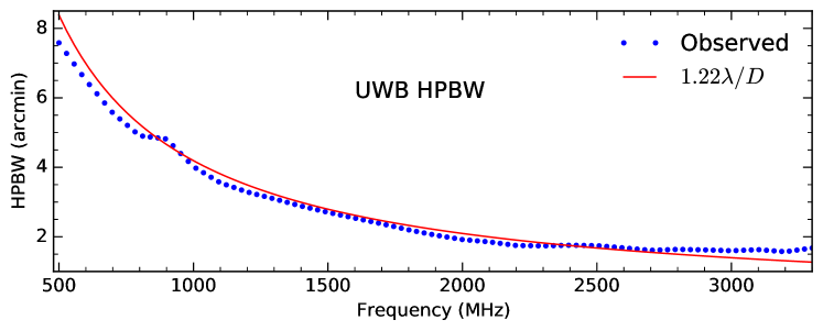
To measure the beam properties of FAST UWB receiver, we directly make mapping observations toward a radio point source 3C286 on the sky on March 26, 2023. The used observation mode is OTF along the direction of the right ascension, and sampling time is 0.2s, scanning velocity is 20 arcsec per second, and the scanning space is 12 arcsec. The mapping area is around , which is large enough for covering the whole beam structure at 500-3300 MHz. Figure 2 displays examples of observed and fitted beam structures at 800, 1400, 2000, and 2900 MHz. Table 2 lists all the measured HPBW at 500-3300 MHz. Figure 3 shows the observed HPBW and the theoretical HPBW = with an assumed telescope diameter m at 500-3300 MHz. We find that below 2400 MHz, the observed HPBW is smaller than the theoretical HPBW. This indicates that the telescope effective aperture is larger than 300 m below 2400 MHz. We noticed that the measured UWB HPBWs are consistent with the FAST 19-beam receiver between 1000-1500 MHz.
2.3 Pointing Accuracy
In FAST feed cabin, the UWB receiver has been placed at the phase center based on many pointing tests. According to antenna measurements, the UWB observations have the same pointing accuracy as FAST 19-beam array. The measured standard deviation of pointing accuracy is better than 7.9 arcsec within zenith angle (ZA) of 26.4∘ (Jiang et al., 2020). For example, the measured pointing error is 7.0 arcsec when measuring the beam structures using the radio point source 3C286 on March 26, 2023. The pointing accuracy of 7.0 arcsec only takes around one twelfth of the HPBW (HPBW) at the frequency of 3300 MHz for the FAST. Therefore, the pointing accuracy well meets the requirement of current UWB receiver observation.
2.4 Antenna Gain and Aperture Efficiency
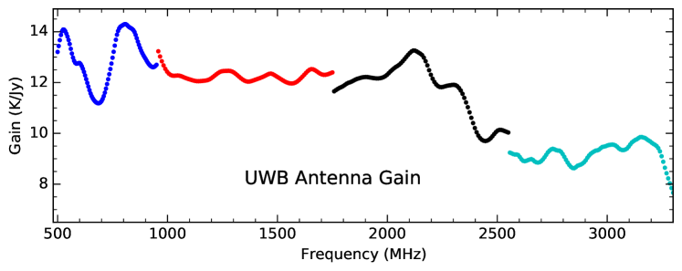
Figure 4 shows the antenna gain distribution within ZA of 26.4∘ for UWB 500-3300 MHz measured by observing a stable flux calibrator 3C286 on March 5, 2023. With absolute measurement of noise dipole, the UWB observed ON-OFF data could be calibrated to antenna temperature () in Kelvin. The flux density (in Jy) of 3C286 within UWB band could be fitted with a polynomial function (Perley & Butler, 2017)
| (1) |
where and are the flux density in Jy and the frequency in GHz, respectively. Then the antenna gain could be estimated as
| (2) |
The derived UWB gain at 1400 MHz is 12.0 K Jy-1, which is lower than that of the FAST 19-beam array (16.0 K Jy-1), mainly because the UWB receiver is uncooled. Up to 3200 MHz, the UWB gain is 9.5 K Jy-1. This meets the requirement of CH observation at 3263.794 MHz. The full antenna gain parameters for UWB 500-3300 MHz could be download online, and are partly listed in Table 2.
Seen from Figure 4, the antenna gain turns to be so low at high frequency end, probably because the reflector precision or the reflection efficiency turns to be low at such high frequency band. The wild fluctuation at low frequency end should be resulted from the serious RFI pollution at 500-920 MHz. Generally, the variation of the monitored antenna gain is less than 10% from August 2022 to March 2023. This indicates that the FAST UWB receiver is relatively stable, but it still needs long-time monitoring for better data calibration.
Assuming the efficiency aperture of FAST is 300 m at 500-3300 MHz, the corresponding geometric illumination area produces a theoretical gain with = 25.6 K Jy-1 (Jiang et al., 2020). The aperture efficiency of the FAST UWB receiver could be estimated by . The maximum and minimum gains are, respectively, 0.56 and 0.30 at 500-3300 MHz. All derived aperture efficiencies are listed in Table 2.
2.5 System Temperature
System temperature is a synthetical contribution from noise of receiver (), continuum brightness temperature of the sky (), emission of the Earth’s atmosphere (), and radiation of the surrounding terrain () (Campbell, 2002; Jiang et al., 2020) as
| (3) |
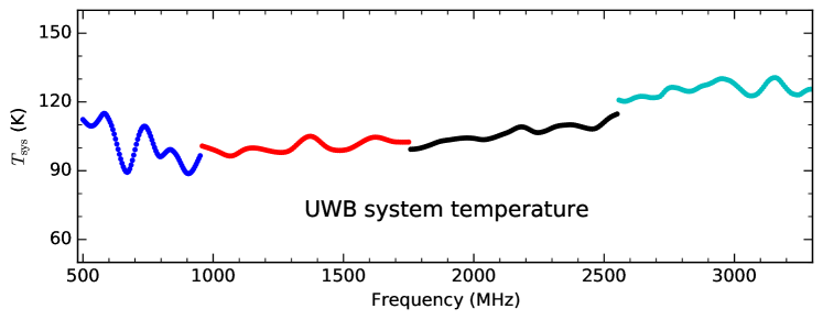
Figure 5 displays the system temperature () within ZA of 26.4∘ for UWB 500-3300 MHz measured by observing cold sky on March 5, 2023. The raw data were converted to antenna temperature with the noise data in Figure 1. The data points, which are deviated from the main curve, are resulted from strong RFI. The UWB system temperatures are 90-130 K for the band of 500-3300ṀHz. The high system temperature mostly arises from the uncooled UWB receiver, whose parameters are presented in Liu et al. (2022). The measured system temperature () for UWB 500-3300 MHz are also listed in Table 2. Such high system temperatures require long-time integration to compensate. In the future, once there is enough space in the feed cabin, the UWB receiver with cryogenic low-noise front-end will be installed, then the lower system noise temperature and higher detection sensitivity could be achieved.
| Frequency | High | Low | Gain | HPBW | ||||
|---|---|---|---|---|---|---|---|---|
| XX | YY | XX | YY | Beam | ||||
| MHz | K | K | K | K | K | K Jy-1 | arcmin | |
| 500 | 19.07 | 21.78 | 1.85 | 2.12 | 13.21 | 0.52 | 112.33 | 7.58 |
| 550 | 20.52 | 23.39 | 2.01 | 2.19 | 13.67 | 0.53 | 110.62 | 7.05 |
| 600 | 21.11 | 24.00 | 2.01 | 2.41 | 12.77 | 0.50 | 112.31 | 6.51 |
| 650 | 21.50 | 24.62 | 2.06 | 2.29 | 11.57 | 0.45 | 93.26 | 6.04 |
| 700 | 21.55 | 24.64 | 2.13 | 2.43 | 11.27 | 0.44 | 99.18 | 5.57 |
| 750 | 21.33 | 24.27 | 2.06 | 2.33 | 12.98 | 0.51 | 107.79 | 5.24 |
| 800 | 20.85 | 23.67 | 1.98 | 2.32 | 14.28 | 0.56 | 96.19 | 4.91 |
| 850 | 19.97 | 22.21 | 1.93 | 2.04 | 13.99 | 0.55 | 98.13 | 4.86 |
| 900 | 18.39 | 20.80 | 1.69 | 2.05 | 12.94 | 0.51 | 88.86 | 4.82 |
| 950 | 17.12 | 19.47 | 1.53 | 1.95 | 12.70 | 0.50 | 96.54 | 4.42 |
| 1000 | 16.92 | 18.96 | 1.61 | 1.81 | 12.41 | 0.48 | 99.19 | 4.02 |
| 1050 | 16.64 | 18.49 | 1.64 | 1.72 | 12.27 | 0.48 | 96.75 | 3.79 |
| 1100 | 16.07 | 17.92 | 1.60 | 1.78 | 12.13 | 0.47 | 97.98 | 3.55 |
| 1150 | 15.68 | 17.45 | 1.52 | 1.55 | 12.06 | 0.47 | 99.94 | 3.42 |
| 1200 | 15.52 | 17.15 | 1.42 | 1.62 | 12.18 | 0.48 | 99.06 | 3.29 |
| 1250 | 15.64 | 17.19 | 1.51 | 1.61 | 12.45 | 0.49 | 98.02 | 3.19 |
| 1300 | 15.97 | 17.42 | 1.65 | 1.67 | 12.40 | 0.48 | 99.28 | 3.09 |
| 1350 | 16.21 | 18.29 | 1.73 | 1.91 | 12.08 | 0.47 | 104.14 | 2.99 |
| 1400 | 16.37 | 18.49 | 1.52 | 1.74 | 12.11 | 0.47 | 103.62 | 2.88 |
| 1450 | 16.65 | 18.85 | 1.59 | 1.90 | 12.29 | 0.48 | 99.48 | 2.79 |
| 1500 | 16.82 | 19.00 | 1.62 | 1.75 | 12.22 | 0.48 | 98.96 | 2.70 |
| 1550 | 17.05 | 18.94 | 1.67 | 1.92 | 11.98 | 0.47 | 101.10 | 2.62 |
| 1600 | 16.96 | 18.95 | 1.57 | 1.83 | 12.11 | 0.47 | 104.14 | 2.54 |
| 1650 | 16.43 | 18.67 | 1.77 | 1.78 | 12.52 | 0.49 | 104.08 | 2.46 |
| 1700 | 15.89 | 18.03 | 1.47 | 1.69 | 12.33 | 0.48 | 102.57 | 2.37 |
| 1750 | 15.13 | 17.21 | 1.39 | 1.69 | 12.40 | 0.48 | 102.50 | 2.29 |
| 1800 | 13.95 | 16.22 | 1.43 | 1.68 | 11.87 | 0.46 | 100.01 | 2.20 |
| 1850 | 13.87 | 15.69 | 1.36 | 1.58 | 12.09 | 0.47 | 101.98 | 2.12 |
| 1900 | 13.61 | 15.24 | 1.24 | 1.48 | 12.22 | 0.48 | 103.36 | 2.05 |
| 1950 | 13.35 | 14.89 | 1.29 | 1.47 | 12.16 | 0.48 | 104.15 | 1.98 |
| 2000 | 13.33 | 14.53 | 1.23 | 1.44 | 12.32 | 0.48 | 104.12 | 1.92 |
| 2050 | 13.08 | 14.26 | 1.26 | 1.35 | 12.68 | 0.50 | 103.68 | 1.89 |
| 2100 | 13.25 | 13.78 | 1.38 | 1.45 | 13.14 | 0.51 | 105.42 | 1.85 |
| 2150 | 11.58 | 13.60 | 1.83 | 1.30 | 13.14 | 0.51 | 107.80 | 1.80 |
| 2200 | 12.90 | 13.32 | 1.23 | 1.31 | 12.27 | 0.48 | 108.70 | 1.75 |
| 2250 | 12.89 | 13.41 | 1.24 | 1.24 | 11.82 | 0.46 | 106.65 | 1.74 |
| 2300 | 13.30 | 14.00 | 1.29 | 1.38 | 11.91 | 0.47 | 108.61 | 1.74 |
| 2350 | 13.57 | 14.14 | 1.36 | 1.42 | 11.40 | 0.45 | 109.91 | 1.75 |
| 2400 | 14.42 | 14.66 | 1.33 | 1.48 | 10.17 | 0.40 | 109.56 | 1.76 |
| 2450 | 14.44 | 14.81 | 1.46 | 1.59 | 9.71 | 0.38 | 108.23 | 1.75 |
| 2500 | 14.89 | 15.54 | 1.45 | 1.48 | 10.10 | 0.39 | 111.14 | 1.75 |
| 2550 | 15.12 | 15.79 | 1.50 | 1.57 | 10.03 | 0.39 | 114.73 | 1.71 |
| 2600 | 14.90 | 15.71 | 1.38 | 1.52 | 9.10 | 0.36 | 120.91 | 1.68 |
| 2650 | 14.02 | 15.20 | 1.60 | 1.49 | 8.98 | 0.35 | 122.40 | 1.65 |
| 2700 | 13.39 | 14.59 | 1.32 | 1.66 | 8.91 | 0.35 | 121.93 | 1.61 |
| 2750 | 13.53 | 14.81 | 1.32 | 1.51 | 9.38 | 0.37 | 126.09 | 1.62 |
| 2800 | 13.45 | 14.68 | 1.50 | 1.43 | 9.15 | 0.36 | 125.32 | 1.64 |
| 2850 | 13.19 | 14.53 | 1.24 | 1.49 | 8.63 | 0.34 | 125.36 | 1.63 |
| 2900 | 12.97 | 14.68 | 1.32 | 1.37 | 8.91 | 0.35 | 127.69 | 1.62 |
| 2950 | 14.65 | 12.54 | 1.47 | 1.52 | 9.32 | 0.36 | 130.12 | 1.61 |
| 3000 | 13.37 | 14.71 | 1.12 | 1.64 | 9.52 | 0.37 | 127.93 | 1.60 |
| 3050 | 13.48 | 14.41 | 1.42 | 1.54 | 9.43 | 0.37 | 123.05 | 1.61 |
| 3100 | 13.50 | 14.09 | 1.31 | 1.45 | 9.50 | 0.37 | 124.84 | 1.63 |
| 3150 | 13.69 | 14.15 | 1.44 | 1.48 | 9.85 | 0.38 | 130.55 | 1.60 |
| 3200 | 13.72 | 14.22 | 1.46 | 1.38 | 9.65 | 0.38 | 125.84 | 1.57 |
| 3250 | 13.61 | 14.12 | 1.41 | 1.33 | 9.03 | 0.35 | 123.22 | 1.62 |
| 3300 | 13.51 | 13.77 | 1.50 | 1.35 | 7.66 | 0.30 | 125.56 | 1.68 |
3 Spectral-line backend and observations
3.1 Backend
At the backend, the whole UWB passband is separated into four subbands, 0-1100 MHz, 800-1900 MHz, 1600-2700 MHz, and 2400-3500 MHz. and each subband has 1048576 channels, so the frequency resolution is 1049.04 Hz (or 1 kHz). Any two adjacent bands have some overlapping frequency ranges to compensate for the shortcomings of the analog filter. The effective frequency ranges are 500-1000 MHz, 900-1800 MHz, 1700-2600 MHz, and 2500-3400 MHz, but the recommended frequency ranges for science observations are 500-950 MHz for UWB-1, 950-1750 MHz for UWB-2, 1750-2550 MHz for UWB-3, and 2550-3300 MHz for UWB-4 (see details in Table 1). Combining the four subbands, the UWB could simultaneously and effectively cover the frequency ranging from 500 to 3300 MHz (see Figure 1). The observed data are recorded in the spectral-line backend using a dual linear polarization (XX and YY) mode. Sampling time is adjustable, e.g., in 0.1s, 0.2s, 0.5s or 1.0s.
3.2 Observation Modes
All the observation modes available in FAST 19-beam array could be used in the UWB receiver, such as Drift, OnOff, OTF, and so on (see details in Jiang et al., 2020). However, we have to remember that the UWB has only one receiver available for observation. The setup parameters for scanning velocity is also the same as the FAST 19-beam array. The maximum scanning velocity is 15 and 30 arcsec per second in direction of DEC and RA, respectively.
3.3 Radio Frequency Interference
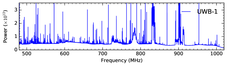
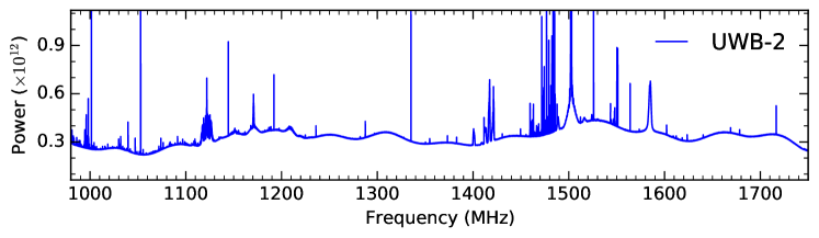
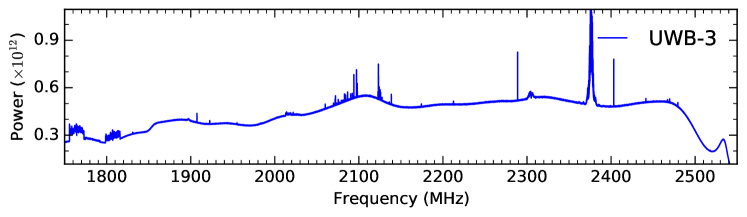
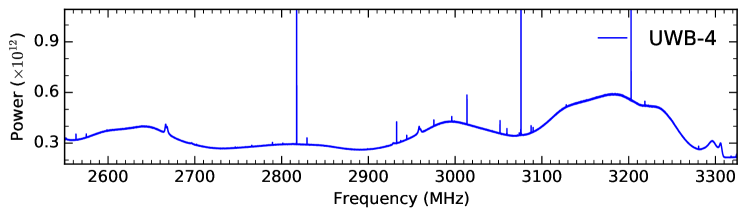
In radio astronomy, radio frequency interference (RFI) becomes more and more serious for radio observational facilities (Kesteven, 2005; An et al., 2017; Zeng et al., 2021; Zhang et al., 2022). The RFI always influences the search and study of the interesting astronomical objects. Figure 6 displays the whole bandwidth with one minute integration using UWB 500-3300 MHz. In many tests, we found that in different sky directions, the RFI distribution at different frequencies is generally similar to that shown in Figure 6, but the intensities are varied. Additionally, the low frequency bands (500-950 MHz) have a more serious RFI pollution than the other high frequency bands (Zhang et al., 2020). All the emission lines basically are RFI, except H I line at 1420 MHz. The extremely strong and evident RFI are from communication satellites and navigation satellites (Wang et al., 2021). Therefore, we must pay attention to avoiding the frequency positions of the strong RFI.
3.4 H I and OH lines
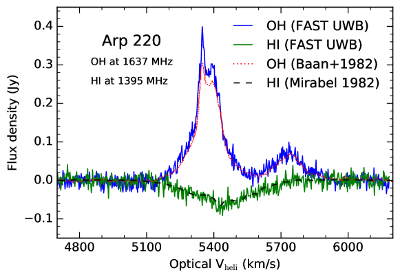
Figure 7 shows Arp 220 (IC 4553) OH emission and H I absorption lines observed by UWB receiver with 600s on-time integration. Arp 220 is a well-known starburst Galaxy with a redshift of 0.01840 (Baan et al., 1982). The observed redshift frequencies of the OH and H I lines are, respectively, 1637 and 1395 MHz, which are covered by UWB-4 and UWB-2 bands, respectively. In 600s integration, the measured spectral rms is around 15.27 mJy with an original channel space of 1.0 kHz. For the H I absorption line of Arp 220 (see the H I line in Figure 7), the measured flux density by the FAST UWB receiver is only 3% higher than the Arecibo 300 m observations (Mirabel, 1982). In addition, for the OH emission line of Arp 220 with the rest frequency of 1665.402 MHz (see the right OH peak in Figure 7), the measured flux density by the UWB is also only 3% higher than the Arecibo 300 m observations (Baan et al., 1982). However, for OH emission line of Arp 220 at its rest frequency of 1667.359 MHz (see the left OH peak in Figure 7), the measured flux density by the UWB is 10% higher than the Arecibo 300 m observations (Baan et al., 1982). This is probably because the OH flux density of Arp 220 at 1665.402 MHz is variable (Darling & Giovanelli, 2002). Generally, our measured (OH and H I lines) flux density and velocity of Arp 220 are well consistent with Arecibo 300 m observations (Baan et al., 1982; Mirabel, 1982; Mirabel & Sanders, 1988). This further suggests that the FAST UWB receiver already has a good performance for spectral science observation at 500-3300 MHz.
4 Summary
The Five-hundred-meter Aperture Spherical radio Telescope (FAST) has already been well running for several years since FAST began its commission when the construction was completed on September 25, 2016. The 19-beam receiver covering 1.05-1.45 GHz was used for most of the science observations. However, high frequency observations, e.g., OH lines at rest frequencies of 1665 and 1667 MHz, are needed to study the star formation in the Milky Way and nearby galaxies. The designed FAST reflector precision actually has met the observational requirement at the high frequency of around 3000 MHz.
Fortunately, a new uncooled ultra wideband (UWB) receiver, simultaneously covering 500-3300 MHz, has been mounted in the FAST feed cabin on June 2022, and has passed a series of observational tests recently. The whole UWB band has been separated into four independent bands, but the recommended frequency ranges for users are UWB-1 for 500-950 MHz, UWB-2 for 950-1750 MHz, UWB-3 for 1750-2550 MHz, and UWB-4 for 2550-3300 MHz. Each band has 1048576 channels in the total frequency range, resulted in a high enough spectral resolution of 1 kHz. At 500-3300 MHz, the antenna gain is around 14.3-7.7 K Jy-1, the aperture efficiency is around 0.56-0.30, the system temperature is around 88-130 K, and the HPBW is around 7.6-1.5 arcmin. The measured antenna parameters above have been listed in the Table 2 for data reduction. The measured standard deviation of pointing accuracy is better than 7.9 arcsec, when zenith angle is within 26.4∘. In addition, the sensitivity and stability of the UWB receiver are confirmed to satisfy expectation by spectral H I and OH observations. By comparison, the measured Arp 220 (OH and H I lines) flux density and velocity are well consistent with Arecibo 300 m observations. This further suggests that the FAST UWB receiver already has a good performance for taking sensitive observations in various scientific goals at 500-3300 MHz.
In the future, once there is enough space in the FAST feed cabin, the UWB receiver with cryogenic low-noise front-end will be installed, then the performance of UWB receiver will be highly improved. For example, the system temperature would decrease 50 K, and the antenna gain would increase 2.5 K Jy-1. That will help us to take more sensitive observations in more various scientific goals than its current status.
Acknowledgements
This work is supported by the National Key R&D Program of China No. 2018YFE0202900. C.P.Z acknowledges support by the West Light Foundation of the Chinese Academy of Sciences (CAS). C.C. and H.F.L thank support by the National Natural Science Foundation of China Nos. 11803044, 11933003, 12173045, and 12273072. This work is sponsored partly by the CAS South America Center for Astronomy (CASSACA) and the China Manned Space Project NO. CMS-CSST-2021-A05. FAST is a Chinese national mega-science facility, operated by the National Astronomical Observatories of CAS (NAOC). We also wish to thank the anonymous referee for comments and suggestions that improved the clarity of the paper.
References
- An et al. (2017) An, T., Chen, X., Mohan, P., & Lao, B. Q. 2017, Acta Astronomica Sinica, 58, 43
- Baan et al. (1982) Baan, W. A., Wood, P. A. D., & Haschick, A. D. 1982, ApJ, 260, L49
- Campbell (2002) Campbell, D. B. 2002, in Single-Dish Radio Astronomy: Techniques and Applications, Astronomical Society of the Pacific Conference Series, vol. 278, edited by S. Stanimirovic, D. Altschuler, P. Goldsmith, & C. Salter, 81–90
- Chen et al. (2020) Chen, H.-Y., Chen, X., Wang, J.-Z., Shen, Z.-Q., & Yang, K. 2020, ApJS, 248, 3
- Cheng et al. (2020) Cheng, C., Ibar, E., Du, W., et al. 2020, A&A, 638, L14
- Ching et al. (2022) Ching, T. C., Li, D., Heiles, C., et al. 2022, Nature, 601, 49
- Darling & Giovanelli (2002) Darling, J., & Giovanelli, R. 2002, ApJ, 569, L87
- Han et al. (2021) Han, J. L., Wang, C., Wang, P. F., et al. 2021, Research in Astronomy and Astrophysics, 21, 107
- Hou et al. (2022) Hou, L., Han, J., Hong, T., Gao, X., & Wang, C. 2022, Science China Physics, Mechanics, and Astronomy, 65, 129703
- Jiang et al. (2020) Jiang, P., Tang, N.-Y., Hou, L.-G., et al. 2020, Research in Astronomy and Astrophysics, 20, 064
- Jiang et al. (2019) Jiang, P., Yue, Y., Gan, H., et al. 2019, Science China Physics, Mechanics, and Astronomy, 62, 959502
- Kesteven (2005) Kesteven, M. 2005, in Proceedings. (ICASSP ’05). IEEE International Conference on Acoustics, Speech, and Signal Processing, 2005., vol. 5, v/873–v/876 Vol. 5
- Li et al. (2021) Li, D., Wang, P., Zhu, W. W., et al. 2021, Nature, 598, 267
- Liu et al. (2022) Liu, H.-F., Jiang, P., He, C., et al. 2022, Research in Astronomy and Astrophysics, 22, 115016
- Mirabel (1982) Mirabel, I. F. 1982, ApJ, 260, 75
- Mirabel & Sanders (1988) Mirabel, I. F., & Sanders, D. B. 1988, ApJ, 335, 104
- Nan et al. (2011) Nan, R., Li, D., Jin, C., et al. 2011, International Journal of Modern Physics D, 20, 989
- Niu et al. (2022) Niu, C. H., Aggarwal, K., Li, D., et al. 2022, Nature, 606, 873
- Perley & Butler (2017) Perley, R. A., & Butler, B. J. 2017, ApJS, 230, 7
- Wang et al. (2021) Wang, Y., Zhang, H.-Y., Hu, H., et al. 2021, Research in Astronomy and Astrophysics, 21, 018
- Xu et al. (2022) Xu, C. K., Cheng, C., Appleton, P. N., et al. 2022, Nature, 610, 461
- Zeng et al. (2021) Zeng, Q., Chen, X., Li, X., et al. 2021, MNRAS, 500, 2969
- Zhang et al. (2021) Zhang, C.-P., Xu, J.-L., Li, G.-X., et al. 2021, Research in Astronomy and Astrophysics, 21, 209
- Zhang et al. (2022) Zhang, C.-P., Xu, J.-L., Wang, J., et al. 2022, Research in Astronomy and Astrophysics, 22, 025015
- Zhang et al. (2020) Zhang, H.-Y., Wu, M.-C., Yue, Y.-L., et al. 2020, Research in Astronomy and Astrophysics, 20, 075