bX \newcolumntypes¿ ¿\arraybackslashX
WiThRay: A Versatile Ray-Tracing Simulator for Smart Wireless Environments
Abstract
This paper presents the development and evaluation of WiThRay, a new wireless three-dimensional ray-tracing (RT) simulator. RT-based simulators are widely used for generating realistic channel data by combining RT methodology to get signal trajectories and electromagnetic (EM) equations, resulting in generalized channel impulse responses (CIRs). This paper first provides a comprehensive comparison on methodologies of existing RT-based simulators. We then introduce WiThRay, which can evaluate the performance of various wireless communication techniques such as channel estimation/tracking, beamforming, and localization in realistic EM wave propagation. WiThRay implements its own RT methodology, the bypassing on edge (BE) algorithm, that follows the Fermat’s principle and has low computational complexity. The scattering ray calibration in WiThRay also provides a precise solution in the analysis of EM propagation. Different from most of the previous RT-based simulators, WiThRay incorporates reconfigurable intelligent surfaces (RIS), which will be a key component of future wireless communications. We thoroughly show that the channel data from WiThRay match sufficiently well with the fundamental theory of wireless channels. The virtue of WiThRay lies in its feature of not making any assumption about the channel, like being slow/fast fading or frequency selective. A realistic wireless environment, which can be conveniently simulated via WiThRay, naturally defines the physical properties of the wireless channels. WiThRay is open to the public, and anyone can exploit this versatile simulator to develop and test their communications and signal processing techniques.
Index Terms:
Channel simulator, channel impulse response, geometric stochastic channel model, MIMO, reconfigurable intelligent surface, Ray tracing, wireless communications.I Introduction
Most wireless communication research is based on channel models. Among many possible models, the geometry-based stochastic channel model (GSCM) is widely used in both academia and industry [meinila2009winner, Lin:Oestges:COST2100, Ghazal:2017, series2017guidelines]. Several technical reports provide guidelines for designing the GSCM, where intensive measurement campaigns for particular scenarios, e.g., urban micro cellular (UMi), urban macro cellular (UMa), and indoor, have determined the channel parameters [3gpp2017study, 3gpp2019study, series2017guidelines].
The latest wireless communication techniques have largely exploited the geometrical properties of the radio frequency (RF) channel at high-frequency bands such as millimeter-wave (mmWave), and very recently terahertz (THz). The geometrical sparsity of the mmWave channel forces the rank deficiency for the high-dimensional channel, making highly complicated systems tractable [Alkhateeb:2014_2, Alkhateeb:2015, Sun:2017]. The assumption about channel sparsity enables the compressive sensing (CS)-based approaches on hybrid beamforming systems[Xinying:2005, Alkhateeb:2014_1, Molisch:2017, Vlachos:2019], reconfigurable intelligent surface (RIS)[Wang:2020, He:2020, Wei:2021, Wei:2022, Hong:2022], and cell-free multiple-input and multiple-output (MIMO) systems [Femenias:2019].
The channel sparsity is evident on the angular domain. The angular spread profile, a picture of the RF signals coming from various directions, confines the covariance matrix of the GSCM to be low-rank. The GSCM relies on stochastic angular spread profiles given with random cluster positions and trajectories of channel paths. The power profiles on the temporal and spectral domains are also stochastic parameters for the GSCM [series2017guidelines]. If we are able to obtain site-specific, not stochastic, angular spread profiles, there would be room to further improve wireless communication techniques by site-specifically optimizing them [He:2019].
Without intensive measurement, the ray-tracing (RT) algorithm gives the detailed geometrical relationship between communication terminals in a deterministic manner [Yun:2015, He:2019]. This deterministic formalism then employs the electromagnetic (EM) equations, which have no randomness when the geometrical parameters are entirely given. There exist various wireless channel simulators using the RT algorithm in academia [Tan:1996, Son:1999, Adana:2005, Boban:2014, Fuschini:2015, Wang:2016, Lecci:2020, Choi:2021] and industry[Hoydis:Sionna, Chen:2021, Sihlbom:2022, WinProp, WirelessInSite, Ranplan, EDX, Volcano, CrossWave, Aster]. Commercial programs have their own acceleration algorithms to boost up the RT algorithm such that they can conduct large-scale simulations; however, the details of simulators are not open to public in general.
The RT algorithm is to find the channel paths following the Fermat’s principle. The methods to implement the RT algorithm are largely divided into two types; the direct algorithm and the inverse algorithm [Catedra:1998]. The direct algorithm tracks all rays that propagate omnidirectionally. Each ray changes the propagating direction when meeting obstacles, i.e., reflections or diffractions. The direct algorithm is also called as the ray launching (RL) method or the shooting and bouncing ray (SBR) method in related works [Fuschini:2015].
The inverse algorithm aims to determine the accurate channel path trajectories from the transmitter (Tx) to the receiver (Rx). The inverse algorithm provides more precise simulation results than the direct algorithm by considering all possible connectivity. However, with an increasing number of objects in the simulation, the complexity of the inverse algorithm becomes challenging. To mitigate the complexity of inverse algorithm, various methods were proposed, e.g., the visible-tree (VT) method and grid partitioning methods such as binary space partitioning (BSP) tree, space volumetric partitioning (VSP) method, and angular Z-Buffer (AZB) method[glassner1989into, Sanchez:1996, Catedra:1998].
| vector | |
| matrix | |
| tensor | |
| matrix with zero elements | |
| inverse of matrix | |
| transpose of matrix | |
| conjugate transpose (Hermitian) of | |
| matrix | |
| absolute value of | |
| norm of vector | |
| tr{} | trace of matrix |
| diag{} | diagonal matrix with as diagonal |
| elements | |
| -th element of vector | |
| -th element of matrix | |
| sub-matrix with -th to -th rows | |
| and -th to -th columns of | |
| inner product of vectors and | |
| outer product of vectors and | |
| convolution of and |
Reflection, diffraction, and scattering are key factors in the implementation of a high-performance RT-based simulator. When considering the scattering, it should be noted that the reflecting and diffracting paths do not always move on the specular channel path trajectory. Thus, to evaluate the channel impulse responses (CIRs) under the scattering, an appropriate definition for the scattering channel paths and EM response models should be given. Most of existing simulators, however, do not implement all these factors simultaneously [Tan:1996, Son:1999, Adana:2005, Boban:2014, Lecci:2020].
In this paper, we present a versatile wireless channel simulator, named as WiThRay (Wireless three-dimensional ray-tracing simulator). Most of RT-based simulators developed for wireless communication systems focus on the EM field examination [Adana:2000, Guan:2013, Degli:2014, Chang:2014, Hur:2016, Lecci:2021]. However, WiThRay is specialized to generate the channel data for performance evaluations of complicated communication techniques. WiThRay gives the channel data with fundamental channel characteristics, e.g., short coherence time for large Doppler spread and small coherence bandwidth for large delay spread. The WiThRay channel data are saved into two types; multi-tap channels in the time domain and subcarrier channels in the frequency domain, making WiThRay suitable to evaluate most of wireless communication techniques. The main features of WiThRay are summarized below:
-
i)
WiThRay employs its own RT algorithm, dubbed as the bypassing on edge (BE) algorithm, which enhances the efficiency of the inverse algorithm.
-
ii)
WiThRay dynamically adjusts the scattering area to include the dominant channel paths.
-
iii)
WiThRay calibrates the scattering grid for MIMO scenarios to ensure that the EM wave propagates in its original waveform, as it does in the real world.
-
iv)
WiThRay judiciously evaluates the multi-tap channel in the fast fading scenario for the development of high-mobility communication systems. The wideband effect and Doppler shift caused by mobile objects are modeled in WiThRay.
-
v)
WiThRay supports the RIS systems by employing the dyadic EM response model.
WiThRay is open to public in our website [WiThRay], and anyone can use this versatile simulator to evaluate various wireless communication techniques. The website [WiThRay] also contains the implementation details of WiThRay.
The rest of this paper is organized as follows. Section II provides the baseline of the general RT algorithm and compares the existing RT-based simulators. Section LABEL:sec3 details the technical features of WiThRay, including the BE algorithm, scattering calibration, geometrical parameter evaluation, and CIR modeling. The output of WiThRay is the discrete channel data, and the discrete sampling process is also described in Section LABEL:sec3. Extensive experimental results are provided in Section LABEL:sec4 showcasing that the channel data generated by WiThRay follow the fundamental theory of wireless channels. After analyzing several wireless communication techniques with WiThRay in Section LABEL:sec5, concluding remarks of the paper are included in Section LABEL:sec6.
| Simulators | RT algorithm | ||||
| methodology | reflection | diffraction | scattering | quasi-3D/full-3D | |
| WiThRay (proposed) | inverse (BE) | multiple | multiple | adjustable scattering area, | full-3D |
| MIMO calibration | |||||
| Ray tube [Tan:1996, Son:1999] | inverse (VT [Sanchez:1996]) | multiple | multiple | - | quasi-3D |
| FASPRO [Adana:2005] | inverse (AZB [Catedra:1998]) | double | single | - | full 3D |
| GEMV [Boban:2014] | inverse | single | multiple | - | full 3D |
| 3DScat [Fuschini:2015, Degli:2004, Degli:2007, Bilibashi:2020] | direct, | multiple | multiple | Fresnel’s ellipsoid [Degli:2004] | full 3D |
| inverse (VT [Sanchez:1996]) | |||||
| CloudRT [Wang:2016, Guan:2013] | inverse [McKown:1991] | multiple | - | - | full 3D |
| Simplified ray tracer [Lecci:2020] | inverse | multiple | - | - | full 3D |
| Wireless InSite [WirelessInSite] | direct (SBR [Ling:1989]), | 30 (SBR), | 4 (SBR), | elliptical region | full 3D |
| inverse (Eigen ray) | 3 (Eigen ray) | 4 (Eigen ray) | |||

II RT-based Simulators
An RT-based simulator is a computer tool used to model the EM propagation in a three-dimensional (3D) environment. The RT algorithm traces EM waves as they propagate through the environment. The simulation considers various factors, such as reflection, diffraction, and scattering, which can affect the signal quality in a real-world environment. The simulation results can be used to predict the signal quality, data rate, and coverage area of a wireless communication system, providing crucial information for the design and optimization of the system.
The general procedure of most RT-based simulators is shown in Fig. 1. A simulator should first build a realistic environment that determines the trajectories of RF signals from the Tx to the Rx. The RT algorithm finds the geometrical channel paths and provides geometrical parameters, e.g., propagation direction, polarization direction, traveling distance, delay, angle of departure, and angle of arrival, which are required to evaluate the CIR. The evaluated CIR should be sampled to test various digital signal processing (DSP) techniques. The details of the procedure are presented in the following:
II-A Loading Map Data
The RT-based simulators generate wireless channel data that change based on the surrounding environment. The RT-based simulators consider important map components that define the channel. In outdoor environments, the dominant components in the map are buildings, terrain, and in some cases, foliage. Indoor environments are largely affected by walls, doors, windows, and large objects, e.g. furniture. Communication terminals should also be loaded at this stage.
Commercial programs, such as Wireless InSite, provide their own 3D map rendering program, but they can also import external rendered data. WiThRay also composes maps by importing 3D coordinate data of objects.
The size of map used for simulation varies depending on its purpose. High-frequency communication scenarios typically assume small areas for simulations. However, for high-speed mobile communications or resolving resource allocation issues in multiple access, the map size may need to increase. Without an efficient algorithm, the RT-based simulator cannot conduct large-scale simulations. WiThRay uses a fast RT algorithm to enable large-scale simulations, which is elaborated in Section LABEL:sec3_2.
II-B RT Algorithm
The RT algorithm is a widely-used technique for simulating EM wave propagation and creating realistic computer graphics. The algorithm tracks the multiple channel paths from the Tx to the Rx, following the Fermat’s principle at points of reflection and diffraction. The direct and inverse algorithms are the two key techniques used to determine these points. In Table II, we compare the RT algorithm adopted in WiThRay to those used in existing RT-based simulators.
II-B1 Methodology
The direct algorithm shoots rays in all directions and tracks their trajectories. When these rays reach an object, they may reflect or diffract. Only the rays that reach the Rx node are transformed into useful information. The accuracy of the direct algorithm depends on the number of rays generated at each branching point (i.e., reflecting or diffracting points). The direct algorithm provides simultaneous results for multiple Rx nodes and is therefore preferable for large-scale simulations. Simulators such as 3DScat and Wireless InSite implement the direct algorithm to support city-scale simulations [Fuschini:2015, WirelessInSite]. In the process of tracing multiple rays, a graphical processing unit (GPU) enables parallel operations, making computation efficient on hardware [Epstein:2010]. However, the number of rays to be tracked in the direct algorithm could be redundant for the simulations with a small number of nodes. Moreover, the direct algorithm suffers from quantization errors, i.e., discretized rays satisfying the Snell’s law do not precisely converge at the Rx node. Therefore, the direct algorithm relies on the concept of acceptance region around the Rx node, which cause inaccurate propagation paths.
The inverse algorithm that only finds the rays of the Fermat’s principle is preferred in simulations that demand high accuracy. Several RT-based simulators, including WiThRay, are based on the inverse algorithm [Tan:1996, Son:1999, Adana:2005, Boban:2014, Fuschini:2015, Wang:2016, Lecci:2020, Choi:2021, WirelessInSite]. However, the inverse algorithm can become complicated when dealing with a large number of objects in the simulation. As the number of objects increases, the number of cases need to be checked for the inverse algorithm grows exponentially. Moreover, the inverse algorithm must search for channel paths for every node-to-node connection, resulting in high complexity.
| Simulators | CIR | |||
|---|---|---|---|---|
| reflection | diffraction | Doppler | RIS | |
| WiThRay (proposed) | directive scattering [Degli:2007] | UTD [Kouyoumijan:1974] | mUE, mSO [Bilibashi:2020] | Faraday’s law[Najafi:2021] |
| Ray tube [Tan:1996, Son:1999] | dyadic reflection [stratton2007electromagnetic] | UTD [Kouyoumijan:1974] | mUE | - |
| FASPRO [Adana:2005] | dyadic reflection [stratton2007electromagnetic] | UTD [Kouyoumijan:1974] | - | - |
| GEMV [Boban:2014] | dyadic reflection [Landron:1996] | ITU-R(P)[series2013recommendation] | mUE, mSO [Bilibashi:2020] | - |
| 3DScat [Fuschini:2015, Degli:2004, Degli:2007, Bilibashi:2020] | directive scattering [Degli:2007] | UTD [Kouyoumijan:1974] | mUE, mSO [Bilibashi:2020] | - |
| CloudRT [Wang:2016, Guan:2013] | directive scattering [Degli:2007] | - | mUE, mSO [Bilibashi:2020] | - |
| Simplified ray tracer [Lecci:2020] | dyadic reflection [stratton2007electromagnetic] | - | - | - |
| Wireless InSite [WirelessInSite] | directive scattering [Degli:2007] | UTD [Kouyoumijan:1974] | mUE | support |
II-B2 Reflection and diffraction
The direct algorithm determines the next direction of the ray when it encounters an object. The ray could reflect off the surface or diffract at the edge. In the direct algorithm, it is straightforward to find the reflecting path while this is not the case for the diffracting path. The Keller’s cone is related to diffraction, and all directions within the cone satisfy the Fermat’s principle, ensuring the shortest path [Keller:62]. Because the direct algorithm cannot determine in advance which direction will lead to the Rx node, it must track all directions, resulting in an increased number of rays to be tracked at diffracting edges. However, in the direct algorithm, the calibration of reflecting and diffracting points can be done sequentially, which reduces the complexity of the process.
The inverse algorithm generates a ray by connecting the mirror image of the Tx or Rx nodes with a straight line. This approach is called as the image method. When a large number of reflections encounter numerous objects, the inverse algorithm needs to produce a significant amount of mirrored images. To confine the number of mirror images, the VT method defines the visible region, known as a ray tube [Sanchez:1996]. In the VT method, the mirror images of the terminal nodes have their own ray tubes. The visibility of ray tubes restricts the number of objects to be checked, and the VT method connects nodes (as a branch of the tree) that see each other through their ray tubes.
The diffracting points in the inverse algorithm should be connected with the mirror images in the flipped space. To obtain the flipped diffraction points on the Keller’s cone, the edges where the diffraction occurs should be flipped multiple times according to the number of reflections in the channel path. However, determining the exact diffracting points is a non-deterministic polynomial-time (NP)-hard problem for a large number of diffractions. WiThRay iteratively solves the distance-minimizing problem to find multiple diffracting points where the shortest channel path lies on.
The grid partitioning method is an acceleration technique that limits the objects under the diffraction. The entire map is divided into grids based on a considered metric, e.g., the volumetric cube in the VSP and the angles in the AZB. The grids under the trajectory of channel path determine possible objects that may have diffracting points. However, the grid partitioning methods might miss some possible connectivity, resulting in degraded accuracy. The BE algorithm of WiThRay only takes the valid diffracting paths in the shadowed area, which efficiently decreases the cases to be checked and achieves good accuracy. The detail of BE algorithm is explained in Section LABEL:sec3_2.
II-B3 Scattering
The paths that satisfy the Fermat’s principle are called as specular paths, which can be found using direct or inverse algorithms. However, in reality, the channel paths that do not follow the Fermat’s principle, known as anomalous paths, can largely affect the channel. For the single point of observation, it can be interpreted as a scattering. These paths can be constructed based on any connection of arbitrary points on objects. Thus, the effect of scattering can be evaluated by considering all the connectivity of discretized points on objects, which is referred to as the propagation graph (PG) theory [Tian:2016, Chen:2017].
The PG-based method that incorporates either the direct or inverse algorithms can focus only on effective channel paths, resulting in a reduced number of rays to be considered. Related works select anomalous paths based on path length, which can be interpreted as the paths within an elliptical region [Degli:2004, Zhang:2022]. However, in Section LABEL:sec3_2, we show that an ellipsoid with a fixed radius may not be a good criterion for choosing the anomalous paths.
II-C CIR Evaluation
The RT algorithm generates the rays that provide geometrical parameters such as polarization direction, propagation direction, traveling distance, delay, angle of departure, and angle of arrival. The RT-based simulators use these parameters to evaluate the CIR for each channel path by applying them to relevant equations. The CIR is a result of antenna radiation, EM propagation, and EM responses of reflections and diffractions. Each of these factors independently affects the channel in general CIR modeling [Schaubach:1992, Tan:1996, Son:1999]. In WiThRay, the RIS response is also combined at this stage. Table III summarizes the factors that RT-based simulators consider for the CIR evaluation.
II-C1 Antenna radiation pattern and propagation loss
The propagation of EM wave from the Tx antenna is determined by the propagating direction, orientation of antenna, and antenna radiation pattern. The intensity of EM wave decreases with the traveling distance, which is called as the propagation loss. The law of energy conservation just concerns the traveling distance, but the atmosphere causes the energy loss and makes the propagation loss to be a function of the carrier frequency. Most of RT-based simulators including WiThRay consider the atmospheric absorption.
II-C2 Reflection
RT-based simulators utilize either the dyadic reflection model [stratton2007electromagnetic] or the directive scattering model [Degli:2007] as the reflection response model. The dyadic reflection model, based on the Faraday’s law, is the canonical formulation. Any EM wave has perpendicular and parallel modes that react independently on the perfectly magnetically conducting (PMC) medium. However, it only deals with the specular paths on the infinite PMC plane and cannot provide a solution for anomalous paths, which ignores the scattering modeling. Therefore, the RT-based simulators that use the dyadic reflection model in Table III do not support scattering [Tan:1996, Son:1999, Adana:2005, Boban:2014, Wang:2016, Lecci:2020].
Scattering models are data-fitting functions. Initially, the Lambertian scattering model provided a good approximation [Degli:2001]. After the measurement campaign for the reflecting signal on buildings in [Degli:2007], the directive scattering model has become a popular model for RT-based simulators[Adana:2005, Boban:2014, Fuschini:2015, Wang:2016, Choi:2021]. The directive scattering model constructs a scattering lobe towards the specular reflection, and the controllable lobe width in the model determines the degree of scattering [Degli:2007]. The directive scattering model also considers the polarization effect, but it does not provide a specific model for the ray with a certain polarization direction [Degli:2011]. On the contrary, WiThRay incorporates the effect of polarization into the directive scattering model.
II-C3 Diffraction
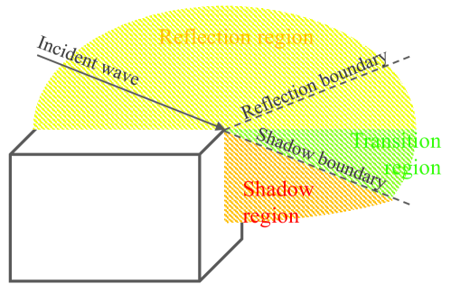
The geometrical theory of diffraction (GTD) is the fundamental theory of diffraction for the RT algorithm. The GTD enables the evaluation of diffraction using rays [Keller:62], but it is an asymptotic equation that fails to solve the equation in the region close to the shadow boundary and reflection boundary in Fig. 2. The uniform theory of diffraction (UTD) provides a valid solution for the unsolved region of the GTD and generalizes the diffraction coefficients for curved wedges [Kouyoumijan:1974]. Although the GTD and UTD are dyadic response models, they provide good approximations for the scattering on edges. Most of RT-based simulators that support the diffraction are based on the UTD as in Table III.
II-C4 Doppler shift
The Doppler shift is caused by the movement of a terminal and the dynamic environment. Many RT-based simulators support the mobile user equipment (mUE) and evaluate the Doppler shift based on its relative speed to a fixed base station (BS). However, not all RT-based simulators consider mobile scattering objects (mSOs) that may affect the trajectory of channel. Without considering mSO, the range of Doppler shift is limited to the speed of mUE, but the Doppler spread might be greater than the Doppler shift by mUE, which fails to reflect real-world scenarios that have mSOs. WiThRay generates realistic channel data by considering the Doppler spread caused by the mSO.
II-C5 RIS response model
The RIS is the strong candidates for 6G wireless communication systems [Huang:2019, Huang:2020, Wu:2020, Jian:2022, Faqiri:2022]. In order to support an RIS system in the RT-based simulator, the EM response on the RIS panel should be evaluated in a series of reflections and diffractions. The RIS panel is a passive element that adjusts the reflections to the intended direction. The reflection of the RIS on a PMC surface is derived using the EM equivalent theorem [Najafi:2021], which is adopted by WiThRay.
II-D Discrete Sampling
The discrete channel data at the BS are observable and controllable signals that can be processed at the DSP unit of wireless communication systems. However, many RT-based simulators do not provide the channel data in the discrete domain e.g., since Wireless InSite does not provide discrete-time domain channel data, DeepMIMO converts the CIR data obtained using Wireless InSite into the discrete channel data [Alkhateeb:DeepMIMO]. On the contrary, WiThRay not only provides the CIR data but also the discrete channel data simultaneously, making the simulator much more efficient. The detailed process of obtaining the discrete channel data is explained in Section LABEL:sec3_6.

![[Uncaptioned image]](/html/2304.11385/assets/x4.png)