An A Quadcopter Autopilot Based on an Adaptive Digital PID Controller
Adaptive Digital PID Control of a Quadcopter
Retrospective-Cost-Based Adaptive Digital PID Control of a Quadcopter
A Retrospective-Cost-Based Adaptive Digital PID Quadcopter Autopilot
Adaptive Digital PID Control of a Quadcopter with Unknown Dynamics
One-Shot Learning for a Quadcopter Autopilot
An adaptive digital autopilot for Multicopters
Experimental Implementation of an Adaptive Digital Autopilot with Applications
An Adaptive Digital Autopilot with Applications
for Fixed-wing Aircraft Control
An Adaptive Digital Autopilot
for Fixed-Wing Aircraft with Actuator Faults
Experimental Flight Testing of a
Fault-Tolerant Adaptive Autopilot for Fixed-Wing Aircraft
Robust Autopilot Learning
Experimental Flight Testing of a Hammerstein Adaptive Autopilot
Experimental Flight Testing of a Hammerstein Adaptive Digital Autopilot for Increased Robustness
Experimental Flight Testing of a Hammerstein Adaptive Digital Autopilot for Parameter Drift Prevention
Experimental Flight Testing of an Adaptive Autopilot
with Parameter Drift Mitigation
Abstract
This paper modifies an adaptive multicopter autopilot to mitigate instabilities caused by adaptive parameter drift and presents simulation and experimental results to validate the modified autopilot. The modified adaptive controller is obtained by including a static nonlinearity in the adaptive loop, updated by the retrospective cost adaptive control algorithm. It is shown in simulation and physical test experiments that the adaptive autopilot with proposed modifications can continually improve the fixed-gain autopilot as well as prevent the drift of the adaptive parameters, thus improving the robustness of the adaptive autopilot.
I Introduction
Multicopters have found significant success in several engineering applications such as precision agriculture [1], environmental survey [2, 3], construction management [4] and load transportation [5]. However, for several reasons, including nonlinear and uncertain dynamics, unknown and uncertain operating environments, and ease of reconfigurability, control of multicopters remains a challenging engineering problem.
Several control techniques have been applied to construct stabilizing controllers for multicopters [6, 7, 8]. However, these techniques often require an accurate plant model and, thus, are susceptible to unmodeled dynamics and physical model parameter uncertainty [9, 10]. Several adaptive control techniques have been applied to address the problem of unmodeled, unknown, and uncertain dynamics such as model reference adaptive control [11, 12], L1 adaptive control [13], and adaptive sliding mode control [14]. In our previous work, we developed an adaptive autopilot based on the retrospective cost adaptive control (RCAC) algorithm [15, 16]. RCAC is described in [17], and is extended to digital PID control in [18].
When the sensor measurements are affected by an unknown bounded disturbance of sufficient amplitude, the parameters updated by the adaptation laws of adaptive controllers may diverge and yield an unstable controller behavior. This phenomenon is called parameter drift [19, 20]. To remedy the parameter drift problem in adaptive control techniques, several extensions have been proposed, such as deadzone nonlinearities, projection operator, and e-modification and modification techniques [21, 22, 23], controller output filtering [24, 25], and controller output averaging [26, 27]. As expected, these modifications entail a tradeoff between robustness to measurement disturbances and tracking performance.
The present paper extends the adaptive autopilot presented in [15]. In this work, it is shown that, in some circumstances, the controller gains optimized by the RCAC algorithm may diverge, eventually leading to the failure of the control system. To mitigate the instability of the control system due to adaptive parameter drift, we extend the adaptive autopilot by including a static nonlinearity before the adaptive controller updated by RCAC. The contribution of this paper is thus the extension of the adaptive autopilot to mitigate parameter drift, the investigation of the effectiveness of three deadzone nonlinearities to reduce the sensitivity of the adaptive controller to sensor noise, and experimental demonstration of the improved robustness of the modified adaptive autopilot.
The paper is organized as follows. Section II briefly reviews the architecture of the adaptive autopilot used in this work. Section III introduces the three deadzone-augmented adaptive autopilots. Section IV describes the simulation and physical flight results to validate the proposed modifications of the adaptive autopilot. Finally, Section V concludes the paper with a discussion of the results.
II Adaptive Autopilot
This section briefly reviews the adaptive autopilot used in this work. The adaptive autopilot is constructed by modifying the fixed-gain autopilot implemented in the PX4 flight stack [28]. The adaptive autopilot’s architecture and notation is described in detail in [15, 16]. The augmentation used for parameter drift mitigation and its implementation is presented in Section III.
The autopilot consists of a mission planner and two nested loops, as shown in Figure 1. The mission planner generates the position, velocity, azimuth, and azimuth rate setpoints from the user-defined waypoints. The outer loop consists of the position controller whose inputs are the position setpoint and velocity setpoints as well as the measured position and measured velocity of the multicopter. The output of the position controller is the thrust vector command. Note that the thrust vector output of the position controller is expressed in the Earth fixed coordinate system. The inner loop consists of the attitude controller whose inputs are the thrust vector setpoint, the azimuth setpoint, and azimuth rate setpoints, as well as the measured attitude and the angular velocity measured in the body-fixed frame. The output of the attitude controller is the moment command. The magnitude of the thrust vector and the moment vector uniquely determine the rotation rate of the four propellers.
The position controller consists of two cascaded linear controllers. The first controller consists of three decoupled proportional controllers. The second controller consists of three decoupled PID controllers. As shown in Figure 2, the two controllers are augmented with adaptive controllers based on the RCAC algorithm.
Similarly, the attitude controller consists of two cascaded controllers. The first controller is a nonlinear almost globally stabilizing controller [29], and the second controller consists of three decoupled PI controllers. As shown in Figure 3, the two controllers are augmented with adaptive controllers based on the RCAC algorithm.
Our prior work in [15, 30, 16] observed that some controller gains updated by RCAC in the adaptive autopilot drifted and eventually caused the adaptive autopilot to fail. Numerical investigations showed that the PI gains of the rate controller diverged even after an acceptable tracking performance was achieved. Thus, we introduce a deadzone in the controller of the inner loop to reduce the sensitivity of the adaptive rate controller. The next section describes three nonlinear functions that are used to implement the deadzone in this work.
III Deadzone-augmented Adaptive Autopilot
This section describes the nonlinear functions used to implement a deadzone in the adaptive autopilot in order to improve noise robustness and prevent the onset of instabilities. To avoid undesirable updates due to noisy or small signals, the performance variable used to define the retrospective cost minimized by the RCAC algorithm is modified, as shown below.
The performance variable used to optimize the adaptive controller is replaced by where is an element-wise nonlinear function. The nonlinear function is chosen to implement a deadzone in the adaptive rate controller, thus suppressing the effect of small values of rate errors on the update of the rate controller gains Note that has six components, that is, two PI gains for each direction. As a result, the inner loop controller in the adaptive autopilot is augmented with the deadzone, as shown in Figure 4. This work investigates the effectiveness of three choices of nonlinear functions to implement a deadzone, as described below.
The first nonlinearity is given by
| (1) |
where Note that is a discontinuous nonlinear function whose output is zero if the input magnitude is less than and is equal to the input if the input magnitude is greater than Figure 5(a) shows the output of for several values of
The second nonlinearity is given by
|
|
(2) |
where and . The parameter is the width of the deadzone and affects the transition to the linear section. In particular, a large value of implies a wide deadzone, and a large value of implies a quicker transition to the linear section. Note that introduces a bias to its output after the transition to the linear section. Figure 5(b) shows the output of for and several values of . Finally, note that is a continuously differentiable nonlinear function.
The third nonlinearity is given by
|
|
(3) |
where and the parameters and are determined such that is continuously differentiable. The parameter is the width of the deadzone and affects the transition to the linear section. Unlike the nonlinear function converges to the asymptote Thus, the nonlinearity acts as an identity function for large input values while zeros out the small values of the input. Finally note that is given by
| (4) |
The parameter is computed similarly. Note that and are computed apriori. Figure 5(c) shows the output of for and several values of

IV Flight Tests
This section describes the numerical simulation and flight test results investigating the effectiveness of the three deadzone nonlinearities described in the previous section on mitigating the parameter drift and adaptive autopilot failure. For these tests, a quadcopter platform is considered.
IV-A Numerical Simulation
We first investigate the effect of the nonlinearities to mitigate the parameter drift in the adaptive autopilot with the jMAVSim quadcopter simulation implemented in the PX4 flight stack.
The three nonlinearities described in the previous section are implemented in the mc_rate_control 111https://github.com/JAParedes/PX4-Autopilot/tree
/RCAC_MC_FW_dev_mavlink/src/modules/mc_rate_control module in PX4.
To investigate and quantify the potential improvements in the adaptive autopilot’s performance, we command the quadcopter to follow a trajectory generated using a second-order Hilbert curve. The quadcopter is commanded to fly the mission with a fixed-gain autopilot and four RCAC-based adaptive autopilots. The first adaptive autopilot does not use deadzone in the pitch rate controller. In contrast, the second, third, and fourth adaptive autopilots use and nonlinear functions to implement the deadzone in the pitch rate controller, respectively.
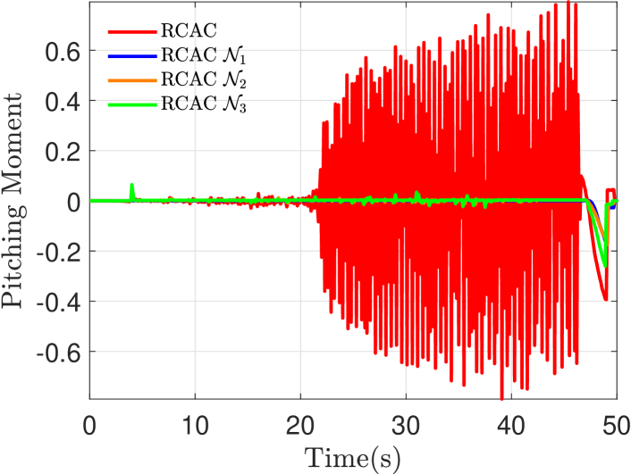
Figure 6 shows the trajectory-following response of the quadcopter with the fixed-gain autopilot and the four adaptive autopilots. Note that all four adaptive autopilots have similar tracking performance. Note that the trajectory-following response of all four adaptive autopilots is better than the fixed-gain autopilot. However, with the first adaptive autopilot, that is, the adaptive autopilot without the deadzone, high-frequency oscillations are observed in the pitch and pitch rate response. Figures 7 and 8 show the pitch-rate error response and the pitching moment in the adaptive autopilot. Note the high-frequency oscillations between 20 and 50 seconds in this case. In contrast, the three adaptive autopilots with deadzones are able to suppress these oscillations as shown in Figures 7 and 8.
Figure 9 shows the frequency content of the pitching moment applied to the quadcopter. Note the large magnitude of the frequency content at higher frequencies generated by the first adaptive autopilot, whereas the high-frequency content is suppressed with the deadzone nonlinearities in the adaptive autopilot. Finally, Figure 10 shows the controller gains updated by the RCAC algorithm in the four adaptive autopilots. Note that without the deadzone nonlinearity, the controller gains drift as shown in the first Figure 10a). With the deadzone nonlinearity in the adaptive autopilot, the controller gain drift is mitigated.


IV-B Physical Flight Tests
Next, we repeat the experiment described in the previous subsection in a physical flight environment using a Holybro X500 quadcopter frame with a Pixhawk 6C flight computer running the PX4 flight software. The flight tests are conducted in the M-air facility at the University of Michigan, Ann Arbor.
Figure 11 shows the trajectory-following response of the quadcopter with the fixed-gain autopilot and adaptive autopilot. Like the simulation experiments, the trajectory-following response is similar for all adaptive autopilots. Moreover, the trajectory-following response of all four adaptive autopilots is better than the fixed-gain autopilot. Furthermore, similar to the simulation experiments, with the adaptive autopilot without the deadzone, high-frequency oscillations are observed in the pitch and pitch rate response. Figures 12 and 13 show the pitch-rate error response and the pitching moment in the adaptive autopilot. Note the high-frequency oscillations between 20 and 50 seconds in this case. In contrast, the three adaptive autopilots with deadzones are able to suppress these oscillations as shown in Figures 12 and 13.
Figure 14 shows the frequency content of the pitching moment applied to the quadcopter. Note the large magnitude of the frequency content at higher frequencies generated by the first adaptive autopilot, whereas the high-frequency content is suppressed with the deadzone nonlinearities in the adaptive autopilot. Finally, Figure 15 shows the controller gains updated by the RCAC algorithm in the four adaptive autopilots. Note that without the deadzone nonlinearity, the controller gains drift as shown in the first Figure 15a). With the deadzone nonlinearity in the adaptive autopilot, the controller gain drift is mitigated.
To quantify the improvements with the deadzone-augmented adaptive autopilots, we compute the cost metrics defined as the root mean square (RMS) value of the position error and defined as the RMS value of the pitch rate error in the mission. Note that the metrics and are computed offline after completing the mission. Figure 16 shows the cost metrics comparing the performance of the four adaptive autopilots in both simulation and flight tests. Note that the position-tracking performance improves with all four adaptive autopilots in both simulation and flight tests. However, without the deadzone nonlinearity, the adaptive autopilot suffers from large pitch rate errors. The deadzone nonlinearities in the adaptive autopilot mitigate the parameter drift and thus improve the pitch rate error response, as shown by the sharp drop in .


V Conclusions
This paper presented three deadzone-augumented adaptive autopilots to increase robustness to adaptive parameter drift caused by noise and small amplitude signals. The deadzones are implemented by three static nonlinear functions. The modified adaptive autopilots were implemented in the PX4 flight stack and their performance was compared in numerical simulation as well as physical flight tests. It was shown that the deadzone nonlinearities can mitigate the high-frequency oscillations that appear in the angular rate response due to adaptive parameter drift without significantly affecting the trajectory-following performance of the adaptive controller. Furthermore, it was shown that, out of the three considered nonlinearities, augmenting RCAC with the simplest discontinuous static function, resulted in the least amount of parameter drift and the most stable flight.
References
- [1] Anandarup Mukherjee, Sudip Misra and Narendra Singh Raghuwanshi “A survey of unmanned aerial sensing solutions in precision agriculture” In J. Netw. Comput. Appl. 148 Elsevier, 2019, pp. 102461
- [2] Arko Lucieer, Steven M de Jong and Darren Turner “Mapping landslide displacements using Structure from Motion (SfM) and image correlation of multi-temporal UAV photography” In Prog. Phys. Geogr. 38.1 Sage, 2014, pp. 97–116
- [3] Victor V Klemas “Coastal and environmental remote sensing from unmanned aerial vehicles: An overview” In J. Coast. Res. 31.5 The Coastal EducationResearch Foundation, 2015, pp. 1260–1267
- [4] Yan Li and Chunlu Liu “Applications of multirotor drone technologies in construction management” In Int. J. Constr. Manag. 19.5 Taylor & Francis, 2019, pp. 401–412
- [5] Daniel KD Villa, Alexandre S Brandao and Mário Sarcinelli-Filho “A survey on load transportation using multirotor UAVs” In J. Intell. Robot. Syst. 98 Springer, 2020, pp. 267–296
- [6] Tiago P Nascimento and Martin Saska “Position and attitude control of multi-rotor aerial vehicles: A survey” In Annu. Rev. Contr. 48 Elsevier, 2019, pp. 129–146
- [7] Julius A Marshall, Wei Sun and Andrea L’Afflitto “A survey of guidance, navigation, and control systems for autonomous multi-rotor small unmanned aerial systems” In Annu. Rev. Contr. 52 Elsevier, 2021, pp. 390–427
- [8] Pedro Castillo, Alejandro Dzul and Rogelio Lozano “Real-time stabilization and tracking of a four-rotor mini rotorcraft” In IEEE Trans. Contr. Sys. Tech. 12.4 IEEE, 2004, pp. 510–516
- [9] Bara J Emran and Homayoun Najjaran “A review of quadrotor: An underactuated mechanical system” In Annu. Rev. Contr. 46 Elsevier, 2018, pp. 165–180
- [10] Roohul Amin, Li Aijun and Shahaboddin Shamshirband “A review of quadrotor UAV: control methodologies and performance evaluation” In Int. J. Autom. Contr. 10.2 Inderscience Publishers (IEL), 2016, pp. 87–103
- [11] Brian Whitehead and Stefan Bieniawski “Model reference adaptive control of a quadrotor UAV” In AIAA Guid. Nav. Contr. Conf. Ex., 2010, pp. 8148
- [12] Zachary T Dydek, Anuradha M Annaswamy and Eugene Lavretsky “Adaptive control of quadrotor UAVs: A design trade study with flight evaluations” In IEEE Trans. Contr. Sys. Tech. 21.4 IEEE, 2012, pp. 1400–1406
- [13] Zongyu Zuo and Pengkai Ru “Augmented L1 adaptive tracking control of quad-rotor unmanned aircrafts” In IEEE. Trans. Aerosp. Elec. Sys. 50.4 IEEE, 2014, pp. 3090–3101
- [14] Omid Mofid and Saleh Mobayen “Adaptive sliding mode control for finite-time stability of quad-rotor UAVs with parametric uncertainties” In ISA trans. 72 Elsevier, 2018, pp. 1–14
- [15] Ankit Goel, Juan Augusto Paredes, Harshil Dadhaniya, Syed Aseem Ul Islam, Abdulazeez Mohammed Salim, Sai Ravela and Dennis Bernstein “Experimental Implementation of an Adaptive Digital Autopilot” In Proc. Amer. Contr. Conf., 2021, pp. 3737–3742
- [16] John Spencer, Joonghyun Lee, Juan Augusto Paredes, Ankit Goel and Dennis Bernstein “An adaptive PID autotuner for multicopters with experimental results” In Proc. Int. Conf. Rob. Autom., 2022, pp. 7846–7853 IEEE
- [17] Yousaf Rahman, Antai Xie and Dennis S. Bernstein “Retrospective Cost Adaptive Control: Pole Placement, Frequency Response, and Connections with LQG Control” In IEEE Control System Magazine 37, 2017, pp. 28–69 DOI: 10.1109/MCS.2017.2718825
- [18] Mohammadreza Kamaldar, Syed Aseem U. Islam, Sneha Sanjeevini, Ankit Goel, Jesse B. Hoagg and Dennis S. Bernstein “Adaptive digital PID control of first-order-lag-plus-dead-time dynamics with sensor, actuator, and feedback nonlinearities” In Advanced Control for Applications 1.1, 2019, pp. e20 DOI: 10.1002/adc2.20
- [19] Bo Egardt “Stability of discrete time controllers” In Stability of adaptive controllers Springer, 1979, pp. 43–86
- [20] Petros A Ioannou and Jing Sun “Robust adaptive laws” In Robust adaptive control Prentice-Hall, 1996, pp. 544–554
- [21] Romeo Ortega and Yu Tang “Robustness of adaptive controllers–a survey” In Automatica 25.5 Elsevier, 1989, pp. 651–677
- [22] B. Ydstie “Transient performance and robustness of direct adaptive control” In IEEE Trans. Autom. Contr. 37.8 IEEE, 1992, pp. 1091–1105
- [23] Eugene Lavretsky and Kevin A. Wise “Robust adaptive control” In Robust and adaptive control: With aerospace applications Springer, 2012, pp. 317–353
- [24] Evgeny Kharisov, Naira Hovakimyan and Karl Åström “Comparison of several adaptive controllers according to their robustness metrics” In AIAA Guid. Nav. Contr. Conf. Ex., 2010, pp. 8047
- [25] Naira Hovakimyan and Chengyu Cao “L1 adaptive control theory: Guaranteed robustness with fast adaptation” SIAM, 2010
- [26] C. Nicol, C.J.B. Macnab and A. Ramirez-Serrano “Robust adaptive control of a quadrotor helicopter” In Mechatronics 21.6 Elsevier, 2011, pp. 927–938
- [27] C.J.B. Macnab “Using RBFs in a CMAC to prevent parameter drift in adaptive control” In Neurocomputing 205 Elsevier, 2016, pp. 45–52
- [28] PX4 User Guide “Multicopter Control Architecture” [Online; accessed 26 February 2023], https://docs.px4.io/main/en/flight_stack/controller_diagrams.html#multicopter-control-architecture
- [29] N.. Chaturvedi, A.. Sanyal and N.. McClamroch “Rigid-Body Attitude Control” In IEEE Control Systems Magazine 31.3, 2011, pp. 30–51 DOI: 10.1109/MCS.2011.940459
- [30] Ankit Goel, Abdulazeez Mohammed Salim, Ahmad Ansari, Sai Ravela and Dennis Bernstein “Adaptive digital pid control of a quadcopter with unknown dynamics” In arXiv preprint arXiv:2006.00416, 2020