Geometric similarities and topological phases in surface magnon polaritons
Department of Physics and Astronomy, University of Pennsylvania, Philadelphia, Pennsylvania 19104, USA
Department of Photonics and Electrical Engineering, Technical University of Denmark, Lyngby 2800, Denmark
Department of Electrical and System Engineering, University of Pennsylvania, Philadelphia, Pennsylvania 19104, USA
Abstract
Highly spatially-squeezed polaritons, with propagation momentum significantly larger than free-space modes at the same frequency, enable varied and extreme control over light-matter interaction. Compared to other polaritons, surface magnon polaritons, the magnetic counterpart of surface phonon polaritons, have received relatively little attention. Here, we investigate the dispersion and properties of surface-magnon polaritons, highlighting the impact of geometric similarities and applying them to various surface-magnon polariton devices in both conventional and topological settings. Our theory predicts a method for strongly localizing and significantly enhancing magnetic fields in the microwave range and developing compact and lossless connectors capable of interconnecting waveguides with vastly different input and output impedances. Our work opens new avenues for manipulating magnetic fields in the microwave regime and for exploring topological phases in polariton platforms.
Introduction
The topological phases of electromagnetic waves are an area of recent interest[1, 2]. A characteristic example of such topological phases is the optical quantum anomalous Hall effect[3, 4, 5], modeled after Chern insulators. Protected by their bulk topology, optical Chern insulators feature unidirectional transport channels at their edges, which are immune to back-scattering due to surface roughness or fabrication imperfections. To achieve the Chern insulator phase, breaking time-reversal symmetry (and reciprocity) is a key requirement, which can be implemented by various means, including by the gyromagnetic effect[6, 7, 8] in ferrimagnetic semiconductors (e.g., yttrium iron garnett, YIG), the gyroelectric effect[4] in magnetized plasmas[9, 10], or in dynamically driven nonlinear materials[11, 12]. As an important practical matter, the strength of gyrotropic responses is high in the microwave regime but is significantly weakened in the near-infrared or visible regime. On the other hand, optical nonlinearity exhibits less frequency dependence but requires intense driving fields due to its weak intrinsic strength. In addition to studying topological phases in pure electromagnetic waves in dispersionless materials, there is a growing interest in exploring topological phases in quasiparticle-settings such as polaritons[13, 14, 15, 16], which can exist in systems with strong response dispersion.
Surface polaritons have proven especially effective in controlling light-matter interactions due to their high spatial squeezing factors. Compared to free-space plane waves at the same frequency, the spatial oscillation of surface polaritons can be significantly larger. Although surface polaritons are subject to material losses[17], they support a wealth of interesting phenomena[18], including strong field enhancements[19], hyperbolic dispersion[20, 21, 22], and extreme modifications of the dynamics of nearby emitters[23], including enabling transitions that are otherwise forbidden[24, 25, 26]. A particularly interesting regime of surface polaritons is in the quasi-static limit with extremely high spatial squeezing factors. In this regime, the electric () and magnetic fields () of electromagnetic waves are approximately decoupled, allowing for independent and virtually arbitrary control of both fields. Two response types have received the majority of attention in the pursuit of high confinement and squeezing, both involving a negative permittivity , namely response below the plasma frequency in metals[27, 28, 29, 30] (also in indium tin oxide[31] and gaseous-phase plasma) or within the reststrahlen band of polar crystals[32]. Alternatively, materials with negative permeability , such as those located close to the ferromagnetic resonances in ferrites[33], can be used, although this approach has received much less attention.
Here we introduce topological phases into surface-magnon polaritons (SMP) by identifying a Chern insulator phase in an array of SMP ring resonators. We present a universal method of geometric scaling SMP structures in the quasi-magnetostatic limit, which allows for easy adjustment of their group velocity and effective impedance while keeping their frequencies unchanged. We apply this geometric scaling method to the SMP Chern insulators and their chiral edge states and develop a compact and lossless interconnect between SMP waveguides with vastly different impedances. Our work paves the way for future exploration of topological phases in polaritonic systems, controlling (e.g., localizing and enhancing) magnetic fields in the microwave regime, and developing topological microwave devices.
Main text
We begin by introducing the geometric scaling rule of electromagnetic waves in the quasi-static limit, before applying it to various structures supporting surface magnon polaritons (SMPs), first in conventional settings (waveguides and ring resonators) and subsequently in topological settings (Chern insulators and chiral edge states).
0.1 Geometric scaling of electromagnetic waves in the quasi-static limit
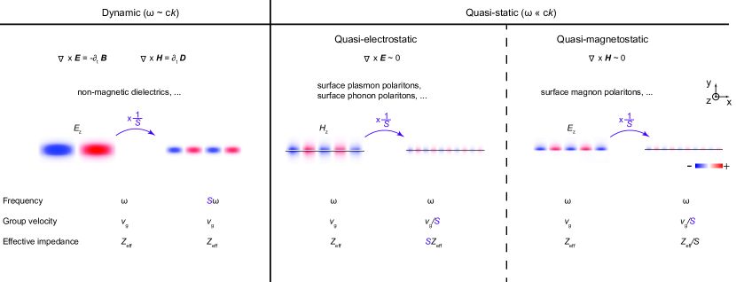
In a waveguide made of non-magnetic dielectrics (Fig. 1), the spatial oscillation frequency of an electromagnetic wave, as characterized by its propagation momentum (), is comparable to its temporal oscillation frequency scaled by the speed of light (). As required by both the (source-free) Faraday law and the Ampere–Maxwell equation in the vacuum, the electric and magnetic fields are comparable in magnitude (). Here is the free-space impedance. In contrast, a different class of solutions to Maxwell’s equations exists where the spatial oscillation is significantly faster than the temporal oscillation (). Such solutions, often referred to as surface polaritons, e.g., exist at the interfaces between air and materials with negative permittivity (as in surface-plasmon polaritons[34, 29] and surface-phonon polaritons[35]) or negative permeability (surface-magnon polaritons). Such surface polaritons are frequently endowed with a very large momentum and an accompanying strong spatial in- and out-of-plane localization (or squeezing), reflecting their substantial coupling to a matter component. As a result, in strongly localized surface-plasmon polaritons (surface-magnon polaritons), the magnetic (electric) field strength nearly vanishes: i.e., (). To still satisfy the Faraday law (Ampere–Maxwell equation) despite the vast difference in field magnitudes, the corresponding () field must be nearly curl-free and can be expressed as the gradient of a scalar potential, similar to the electrostatic (magnetostatic) fields at zero frequency.
Electromagnetic fields scale very differently in dynamic settings compared to quasi-static settings. When a structure consisting of a dispersionless medium is shrunk by a factor of in all dimensions (Fig. 1), the eigenfrequencies of any modes supported by structure increase by a factor of from to ; as does the spatial oscillation frequency (e.g., momenta increase from to ). Meanwhile, the electric and magnetic fields, E and H, scale in the same way, leaving the effective impedance unchanged, since . The group velocity is similarly invariant in the dispersionless case. In contrast, the and fields are effectively decoupled in the quasi-static limit, allowing them to vary independently under scaling transformations. For example, when a polaritonic waveguide is shrunk by a factor of , the operating frequency remains unchanged. Meanwhile, only the () field is increased by a factor of in the quasi-electrostatic (quasi-magnetostatic) setting, while the complementary fields () remains nearly unchanged. The effective impedance is thus increased (decreased) by a factor of while the group velocity is reduced by a factor of .
0.2 SMP waveguides
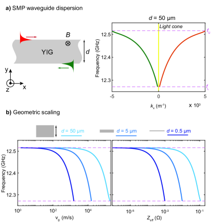
Motivated by these simple considerations, we derive the surface-magnon polariton (SMP) waveguide dispersions and show how they change under geometric scaling. An SMP waveguide consists of a finite-width ferrimagnetic semiconductor (e.g., YIG) placed in an external magnetic field, , directed tangentially to the waveguide’s surfaces which are assumed to span the plane (Fig. 2a). The YIG magnetic permeability tensor[36] can be expressed as
| (1) | ||||
| (2) |
Here the column vectors of the unitary matrix label the optical principle axes and of the magnetized YIG. Along the principal axes , the permeability is:
| (3) |
Here is the frequency, , , and is the gyro-magnetic ratio of YIG. In all calculations below, we take the external magnetic field , and the magnetization of YIG as its saturated magnetization , following Refs. 36 and 37. Meanwhile, the Gilbert damping constant is taken to be , consistent with recent experiments[38, 39]. In finite 3D YIG samples, the build-up of a demagnetization field also affects the permeability[36, 40]: in the present 2D context, however, the demagnetization field is zero since the sample extends infinitely in the direction of the external magnetic field. See Methods for more details on the material properties of YIG. In addition to a continuum of bulk electromagnetic modes, a set of localized SMP modes are found at the interfaces between YIG and air (Fig. 2a). These modes are also known as magnetostatic surface waves (MSSW)[41, 40], which are usually derived under the magnetostatic approximation (). Here, we solve the full Maxwell’s equations without such approximations throughout, which leads to a few important deviations from the conventional MSSW results shown later.
The SMP waveguide modes are bounded in frequency, lying between a lower limit of and an upper limit of . The frequency is often denoted by in the MSSW literature[40], as it represents the resonance frequency of a forward volume wave with magnetic field polarized perpendicularly to the external magnetic field, i.e., with . For frequencies outside this range, there exists a continuum of bulk modes below but no modes with above . We note that our calculated SMP dispersion starts from a finite momentum at the lower frequency bound , as opposed to starting from zero momentum as in the MSSW literature derived under the magnetostatic approximation[41, 40]. The SMP dispersion consists of two branches (Fig. 2a): in one branch (red curve) the mode is localized on the upper interface and travels to the right; in the other (green curve), it is localized on the bottom interface, traveling leftward. Such waveguide modes are non-reciprocal in nature, consistent with the fact that both time-reversal symmetry and reciprocity are broken by the YIG permeability. The SMP dispersion exhibits a symmetry because the two SMP branches are related by the symmetry of the waveguide. The momentum of both SMP branches, , is significantly larger than that of free-space modes at the same frequencies (), confirming the quasi-magnetostatic nature of the SMP modes.
Next, we geometrically scale SMP waveguides to different widths () and confirm the scaling rules of SMP modes. As the waveguide’s width () is shrunk by factors of , from to to , the frequency range of SMP remains unchanged, while the in-plane momentum increases by factors of 10 (Fig. 2b). Accordingly, the group velocity and the effective impedance also decrease by factors of , consistently with the predictions above.
0.3 SMP ring resonators
SMP resonances can be built by bending an SMP waveguide into a ring resonator with inner radius , outer radius , and width (Fig. 3a). The resulting rotational symmetry quantizes the SMP ring resonances according to their azimuthal numbers : , where is the polar angle in cylindrical coordinates. Similarly to the SMP waveguide modes, the cylindrical SMP resonances with () live at the inner (outer) surface and travel in the counter-clockwise (clockwise) direction. The SMP resonance frequencies (circles) are in good agreement with the SMP waveguide dispersion (dashed lines) when associating the momentum of the SMP resonance with the azimuthal number according to , where , as demonstrated in the example with and . See Supplementary Information for more details. As a result, the SMP resonance frequency increases with . Our calculations indicate that SMP resonances with opposite are very close in frequency, but they are not identical as previously noted in the MSSW literature[41, 40]. Similar geometric scaling behavior can be observed in SMP ring resonances (Fig. 3b): as the entire structure is scaled down by a factor of 10 (100), the SMP resonance frequencies labeled by red squares (blue triangles) remain nearly identical to their original values labeled as black circles.
0.4 SMP Chern insulators and chiral edge states
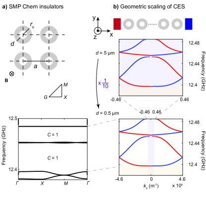
A Chern insulator made of SMPs can be created by arranging SMP ring resonators in a square lattice array (as shown in Fig. 4a). Each ring in the lattice is identical to the one shown in Fig. 3b, with a width of . When the lattice constant is , the band structure of this SMP ring resonator array consists of nearly dispersionless bands, which are built from ring resonator modes with opposite (such as or ). The only exception is the three highly dispersive bands, which are mostly built from and modes. Many of the SMP energy gaps are topologically non-trivial, characterized by non-zero Chern numbers (e.g., ), which is consistent with the analysis of indices of the eigenmodes at high symmetry points ( and ) in the band structure. See Supplementary Information for more details. To confirm the Chern numbers of the SMP energy gaps, a super-cell geometry is constructed to check for unidirectional chiral edge states (CESs) at the interfaces between SMP ring resonators and perfect electric conductors (PECs) (Fig. 4b). Indeed, pairs of CESs are found between 12.397 and 12.452 GHz and also between 12.455 and 12.483 GHz. These pairs of CESs, labeled by red and blue lines, localize at opposite interfaces (left and right) and travel in opposite directions (downward and upward). We note that compared to previous photonic Chern insulators that also use YIG[3, 6, 7], our unit cells and feature sizes are about 2–3 orders of magnitude smaller, which confirms the high spatial squeezing factors of our SMP.
Both the SMP Chern insulator and CES can also be geometrically scaled: when the unit cell is scaled down by a factor of , reducing to and reducing to , the band Chern numbers remain the same and the CES frequencies remain unchanged (Fig. 4b, bottom panel), but now with 10 times the momentum . Accordingly, the waveguide group velocity and effective impedance are also reduced by factors of .
0.5 Topological interconnects between SMP waveguides with arbitrary effective impedance
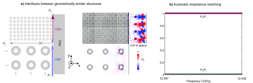
A compact and lossless interconnect can be constructed between geometrically similar SMP chiral edge states. Specifically, an SMP Chern insulator (the bottom section of Fig. 5a) is interfaced with a geometrically scaled-down version of itself (by a factor of , the top section), both terminated by a PEC on the right. Following the rules of geometrical scaling (Fig. 1), the two SMP Chern insulators, with bigger and smaller unit cells, share the same frequencies, as do the CES at their interfaces with the PEC on the right. For an input power of into the bottom CES (blue arrow), due to its unidirectional nature, there are only two possible output channels. It can travel through the scaled-down version chiral edge state (purple arrow, labeled as CES′) to the top (), which has a significantly reduced group velocity and effective impedance. Otherwise, it has to propagate through trivial edge states (gray arrow) at the interface between two Chern insulators of the same Chern numbers towards the left (). By engineering the interface configuration, one can eliminate such trivial edge states and thus ensure that and (Fig. 5b). See Supplementary Information for more details on trivial edge state engineering. Overall, we have developed a lossless and compact interconnect between SMP waveguides with significantly different effective impedance and group velocities, based on topology and geometric similarity.
Discussion and conclusion
Our proposed structures can be readily fabricated and tested in experiments. To begin with, though our calculations are for 2D YIG structures, similar results can also be achieved in 3D structures defined in thin-film YIG and placed in between two metallic plates—a similar geometry as in previous experimental demonstrations[6, 7]. Furthermore, thin-film YIG wafers are readily available with narrow ferromagnetic resonance linewidths[37] (down to 1.5oe). Standard etching mechanisms have also been reported in the literature[42, 43] to define proposed structures such as YIG waveguides and ring resonators. Our derived geometric scaling rules pose a few limitations on the geometric parameters in practice, as summarized in Table. E1. On the one hand, very wide waveguides (e.g., ) do not produce enough spatial squeezing to be in the quasi-magnetostatic limit and the SMP dispersion becomes insensitive to the change of . On the other hand, in extremely narrow waveguides (e.g., ), the magnetic dipole exchange interaction can no longer be neglected, as we have assumed in our calculations. Further investigation into such small structures allows exploration into the non-local regime of electromagnetic waves[44, 45], where more complex and intriguing phenomena may be discovered.
In summary, we introduce topological phases into surface magnon polaritons through the example of Chern insulators. By applying the geometric scaling rules in the quasi-magnetostatic regime, we demonstrate a powerful mechanism to adjust the speed of light and the effective impedance of SMP waveguides. Based on this scaling mechanism, we also develop a topological and lossless interconnect between SMP waveguides with vastly different impedance. Our work opens up new possibilities in exploring topological phases in polaritonic systems, manipulating magnetic fields in the microwave regime, and developing compact topological devices for microwave applications.
Methods
0.6 Permeability and permittivity of YIG
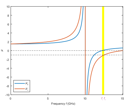
The ferromagnetic resonance (FMR) of YIG is at frequency . Close to the FMR, drops sharply to a negative value, and it reaches at the frequency of , which sets the upper frequency bound for SMP. Meanwhile, if transformed back into the Cartesian coordinate, the diagonal terms of the permeability matrix read , which follows the general trend of near the FMR. Meanwhile reach 0 at , which defines the lower frequency bound for SMP. Taken together, SMPs are confined to the frequency regime of above () and below (), as shown in Fig. E1. Out of the two loss mechanisms in YIG, magnetic and electric, in highly squeezed SMP with much stronger magnetic fields than electric fields, the magnetic loss (Gilbert damping) dominates over the electric (dielectric loss tangent). The Gilbert damping constant of YIG varies strongly with temperature and is taken to be in our calculations, which is at the higher end of reported values[46, 38]. The permittivity of YIG is taken to be , while the dielectric loss tangent (nominally around in the literature[47]) is neglected in our calculations as it is dominated by the Gilbert damping constant in the quasi-magnetostatic limit.
0.7 Data availability
The data within this paper are available from the corresponding author upon request.
0.8 Acknowledgments
The authors acknowledge stimulating conversations with Nicholas Rivera, Jamison Sloan, and Marin Soljačić. This work was partly supported by the U.S. Office of Naval Research (ONR) through grant N00014-20-1-2325 on Robust Photonic Materials with High-Order Topological Protection and grant N00014-21-1-2703, the Air Force Office of Scientific Research through grant FA9550-21-1-0299. Work by T.C. is supported by the Villum Fonden (42106). Work by E.J.M is supported by the Department of Energy under grant DE-FG02-84ER45118.
0.9 Author Contributions
C.Q. and B.Z. conceived the project. C.Q. performed numerical simulations assisted by J.J. C.Q. and B.Z. wrote the paper with input from all authors. All authors discussed the results. B.Z. supervised the project.
0.10 Competing interests
The authors declare no competing interest.
0.11 Correspondence
Correspondence should be addressed to B.Z. (email: bozhen@sas.upenn.edu).

| Quasi-static & Dipolar regime | |
|---|---|
| Waveguide width (µm) | – |
| Momentum (m-1) | – |
| Group velocity (m/s) | – |
| Impedance () | – |
References
References
- [1] Ozawa, T. et al. Topological photonics. Reviews of Modern Physics 91, 015006 (2019).
- [2] Lu, L., Joannopoulos, J. D. & Soljačić, M. Topological photonics. Nature Photonics 8, 821–829 (2014).
- [3] Wang, Z., Chong, Y., Joannopoulos, J. D. & Soljačić, M. Reflection-free one-way edge modes in a gyromagnetic photonic crystal. Physical Review Letters 100, 013905 (2008).
- [4] Haldane, F. D. M. & Raghu, S. Possible realization of directional optical waveguides in photonic crystals with broken time-reversal symmetry. Physical Review Letters 100, 013904 (2008).
- [5] Rechtsman, M. C. et al. Photonic Floquet topological insulators. Nature 496, 196–200 (2013).
- [6] Wang, Z., Chong, Y., Joannopoulos, J. D. & Soljačić, M. Observation of unidirectional backscattering-immune topological electromagnetic states. Nature 461, 772–775 (2009).
- [7] Skirlo, S. A. et al. Experimental observation of large Chern numbers in photonic crystals. Physical Review Letters 115, 253901 (2015).
- [8] Bahari, B. et al. Nonreciprocal lasing in topological cavities of arbitrary geometries. Science 358, 636–640 (2017).
- [9] Prudêncio, F. R. & Silveirinha, M. G. Ill-defined topological phases in local dispersive photonic crystals. Physical Review Letters 129, 133903 (2022).
- [10] Qian, C. et al. Topological electromagnetic waves in dispersive and lossy plasma crystals. arXiv preprint arXiv:2303.04903 (2023).
- [11] He, L. et al. Floquet Chern insulators of light. Nature Communications 10, 4194 (2019).
- [12] Fang, K. & Wang, Y. Anomalous quantum Hall effect of light in Bloch-wave modulated photonic crystals. Physical Review Letters 122, 233904 (2019).
- [13] Basov, D., Fogler, M. & García de Abajo, F. Polaritons in van der Waals materials. Science 354, aag1992 (2016).
- [14] He, L., Wu, J., Jin, J., Mele, E. J. & Zhen, B. Polaritonic Chern insulators in monolayer semiconductors. Physical Review Letters 130, 043801 (2023).
- [15] Karzig, T., Bardyn, C.-E., Lindner, N. H. & Refael, G. Topological polaritons. Physical Review X 5, 031001 (2015).
- [16] Liu, W. et al. Generation of helical topological exciton-polaritons. Science 370, 600–604 (2020).
- [17] Khurgin, J. B. How to deal with the loss in plasmonics and metamaterials. Nature Nanotechnology 10, 2–6 (2015).
- [18] Basov, D. N., Asenjo-Garcia, A., Schuck, P. J., Zhu, X. & Rubio, A. Polariton panorama. Nanophotonics 10, 549–577 (2020).
- [19] Jornada, F. H., Xian, L., Rubio, A. & Louie, S. G. Universal slow plasmons and giant field enhancement in atomically thin quasi-two-dimensional metals. Nature Communications 11, 1013 (2020).
- [20] Yang, Y. et al. Type-I hyperbolic metasurfaces for highly-squeezed designer polaritons with negative group velocity. Nature Communications 10, 2002 (2019).
- [21] Hu, G. et al. Real-space nanoimaging of hyperbolic shear polaritons in a monoclinic crystal. Nature Nanotechnology 1–7 (2022).
- [22] Passler, N. C. et al. Hyperbolic shear polaritons in low-symmetry crystals. Nature 602, 595–600 (2022).
- [23] Tiene, A. et al. Extremely imbalanced two-dimensional electron-hole-photon systems. Phys. Rev. Res. 2, 023089 (2020). URL https://link.aps.org/doi/10.1103/PhysRevResearch.2.023089.
- [24] Rivera, N., Kaminer, I., Zhen, B., Joannopoulos, J. D. & Soljačić, M. Shrinking light to allow forbidden transitions on the atomic scale. Science 353, 263–269 (2016).
- [25] Rivera, N. & Kaminer, I. Light–matter interactions with photonic quasiparticles. Nature Reviews Physics 2, 538–561 (2020).
- [26] Sloan, J., Rivera, N., Joannopoulos, J. D., Kaminer, I. & Soljačić, M. Controlling spins with surface magnon polaritons. Physical Review B 100, 235453 (2019).
- [27] Reather, H. Surface plasmons on smooth and rough surfaces and on gratings. Springer Tracts Mod. Phys 111, 345–398 (1988).
- [28] Zayats, A. V., Smolyaninov, I. I. & Maradudin, A. A. Nano-optics of surface plasmon polaritons. Physics reports 408, 131–314 (2005).
- [29] Grigorenko, A. N., Polini, M. & Novoselov, K. Graphene plasmonics. Nature Photonics 6, 749–758 (2012).
- [30] García de Abajo, F. J. Graphene plasmonics: challenges and opportunities. ACS Photonics 1, 135–152 (2014).
- [31] West, P. R. et al. Searching for better plasmonic materials. Laser & Photonics Reviews 4, 795–808 (2010).
- [32] Palik, E. History of far-infrared research. I. The Rubens era. JOSA 67, 857–865 (1977).
- [33] Fuller, A. B. Ferrites at microwave frequencies. 23 (IET, 1987).
- [34] Jablan, M., Buljan, H. & Soljačić, M. Plasmonics in graphene at infrared frequencies. Physical Review B 80, 245435 (2009).
- [35] Caldwell, J. D. et al. Low-loss, infrared and terahertz nanophotonics using surface phonon polaritons. Nanophotonics 4, 44–68 (2015).
- [36] Pozar, D. M. Microwave engineering (Wiley, 2011), 4 edn.
- [37] Dubs, C. et al. Sub-micrometer yttrium iron garnet LPE films with low ferromagnetic resonance losses. Journal of Physics D: Applied Physics 50, 204005 (2017).
- [38] Kosen, S., van Loo, A. F., Bozhko, D. A., Mihalceanu, L. & Karenowska, A. D. Microwave magnon damping in YIG films at millikelvin temperatures. APL Materials 7, 101120 (2019).
- [39] Pirro, P., Vasyuchka, V. I., Serga, A. A. & Hillebrands, B. Advances in coherent magnonics. Nature Reviews Materials 6, 1114–1135 (2021).
- [40] Gurevich, A. G. & Melkov, G. A. Magnetization oscillations and waves (CRC Press, 1996).
- [41] Stancil, D. D. Theory of magnetostatic waves (Springer Science & Business Media, 2012).
- [42] Chumak, A. V. et al. Advances in magnetics roadmap on spin-wave computing. IEEE Transactions on Magnetics 58, 1–72 (2022).
- [43] Zhu, N., Zhang, X., Han, X., Zou, C.-L. & Tang, H. X. Inverse Faraday effect in an optomagnonic waveguide. Physical Review Applied 18, 024046 (2022).
- [44] Cornelissen, L. J. et al. Nonlocal magnon-polaron transport in yttrium iron garnet. Physical Review B 96, 104441 (2017).
- [45] Yang, Y. et al. A general theoretical and experimental framework for nanoscale electromagnetism. Nature 576, 248–252 (2019).
- [46] Jermain, C. et al. Increased low-temperature damping in yttrium iron garnet thin films. Physical Review B 95, 174411 (2017).
- [47] How, H., Shi, P., Vittoria, C., Kempel, L. C. & Trott, K. D. Single-crystal YIG phase shifter using composite stripline structure at band. Journal of Applied Physics 87, 4966–4968 (2000).