Nonreciprocal ultrastrong magnon-photon coupling
in the bandgap of photonic crystals
Abstract
We observe a nonreciprocal ultrastrong magnon-photon coupling in the bandgap of photonic crystals by introducing a single crystal YIG cylinder into copper photonic crystals cavity as a point defect. The coupling strength reaches up to 1.18 GHz, which constitutes about 10.9% of the photon energy compared to the photon frequency around 10.8 GHz. It is fascinating that the coupling achieves unidirectional signal transmission in the whole bandgap. This study demonstrates the possibility of controlling nonreciprocal magnon-photon coupling by manipulating the structure of photonic crystals, providing new methods to investigate the influence of magnetic point defects on microwave signal transmission.
I Introduction
Cavity magnonics, which is based on coupling between magnons and cavity photons, has become a powerful platform for studying the hybrid quantum systems [1, 2, 3, 4, 5]. In this regime, information is carried and transmitted by the polarons that are generated by the coupling between magnons and photons. Since Soykal and Flatté proposed magnon-photon coupling (MPC) in 2010 [6, 7], many studies have demonstrated it in experiments and theories. Huebl et al. achieved a strong coupling with YIG films and coplanar waveguides at mK temperatures in 2013 [8]. Soon after, Zhang et al. accomplished experiments at room temperatures with an yttrium iron garnet (YIG) sphere and a three-dimensional (3D) microwave cavity [9]. A number of researchers have also reported a lot of interesting and valuable studies, like dissipative couplings [10, 11], indirect couplings [12, 13, 14], nonreciprocal couplings [15, 16, 17, 18] in coupled systems. These studies show great promise in a wide range of applications in quantum information processing. Most importantly, strong coupling is necessary in the coupling system for broadening the frequency range. Researchers have achieved the strong MPC in different cavity systems with the magnons which have large spin density, such as 3D rectangular cavity [19, 20], split-ring resonator [21, 22, 23], inverted pattern of split-ring resonator [11], cross-line cavity [15] and photonic crystals (PCs) [24].
PCs are a kind of artificial inhomogeneous electromagnetic structures with definite refractive index or periodic dielectric constant [25, 26, 27]. Wang et al. introduced one-way modes analogous to quantum Hall edge states generalized with gyromagnetic materials [28], and observed the so-called chiral edge states [29] as well as in other research area [30, 31, 32, 33]. In 2015, Skirlo et al. constructed a ferrimagnetic PCs with a band structure comprising high chern numbers and the dispersion relations of one-way edge modes for the first time in any quantum Hall effect or quantum anomalous Hall effect system [34]. Liu and Houck discovered an attractive experimental phenomenon that a hybridization induced by the strong MPC can create localized cavity modes that live within the photonic bandgap [35]. Built on these interesting investigations, we realized an ultrastrong MPC with a coupling strength of 1.05 GHz and the coupling efficiency comes up to 11.7% in PCs with a ferrimagnetic point defect in 2019 [24]. This research indicates that PCs is an appropriate system to investigate the cavity magnonics .
In this work, a nonreciprocal ultrastrong coupling is realized in the band gap of the PCs with a magnetic point defect. Results show an ultrastrong interaction between the ferromagnetic resonance (FMR) mode and the defect mode of the PCs. In addition to broken time-reversal symmetry (TRS) of the system, microwave is allowed to transmit along one direction in the bandgap by tuning strength and direction of the applied magnetic field.
II Experiments
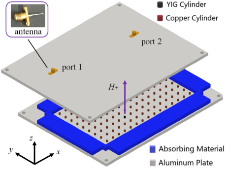
As illustrated in Fig. 1, our device consists of a 2D PCs with a point defect by substituting a YIG cylinder for a copper cylinder. A 2D chamber is constructed by two aluminum plates with 5mm of separation and surrounded by some microwave absorbing materials. All of the cylinders which have a diameter and a height as 5 mm are placed in the chamber and the lattice constant of the 2D simple cubic structure is defined as 20 mm. A vector network analyzer (VNA, Agilent E8363B) is employed to feed microwaves by connecting to two antennas. Meanwhile, a static magnetic field along direction is applied by an electromagnet. We choose a single crystal YIG as the magnetic material because of its low microwave magnetic-loss parameter and high-spin-density [36]. Our YIG has a saturation magnetization = 1750 G, a gyromagnetic ratio = 2.8 MHz/Oe, and a linewidth of 10 Oe.
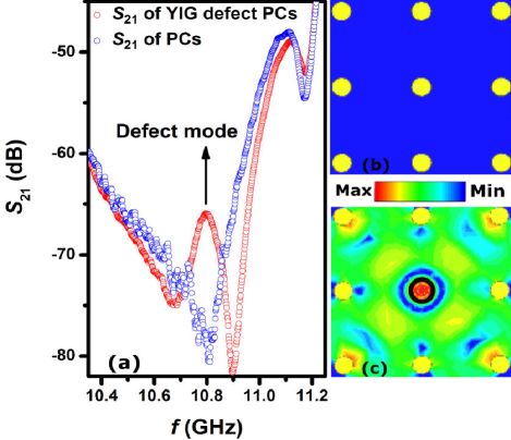
The scatter parameter (i, j = 1, 2) is measured to characterize the experimental phenomena discussed subsequently. represents the microwave transmission signal from port to port . Figure 2(a) denotes the transmission coefficients of copper cylinder PCs and YIG defect PCs as a function of frequency. Additional simulation results are introduced to understand experimental results. The microwave magnetic field distribution at 10.8 GHz in PCs and YIG defect PCs are illustrated as Figs. 2(b) and 2(c), respectively. It reveals that a strong gathering of the magnetic energy could be observed at the position of YIG cylinder [black circle on Fig. 2(c)]. It implies a localized mode within the band gap is excited. Focus on this eigen mode, we swept the applied static magnetic fields with a frequency range between 10.0 and 11.5 GHz.
III RESULTS AND DISCUSSION
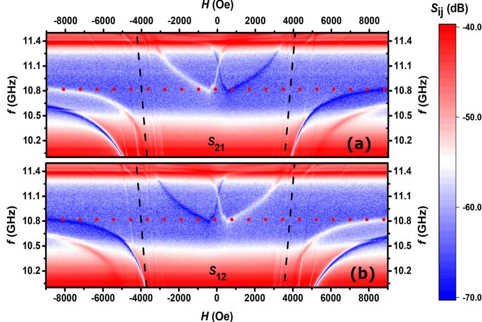
The density mapping image of the magnitude of transmission coefficient is shown in Fig. 3. Figures 3(a) and 3(b) display the density mapping images of the magnitude of the microwave transmission coefficient and , respectively. The spectra were measured by altering the static magnetic field from -9000 to 9000 Oe with a step size of 18 Oe. An anti-crossing behavior arises owing to the coupling between magnons and photons. According to our experiments, magnons are supplied by FMR mode and the photons are introduced by the eigen defect mode of the microwave cavity. The FMR mode (black dashed line in Fig. 3) is calculated by the Kittel equation [37]:
| (1) |
The demagnetizing factors cannot be calculated analytically as the demagnetizing field is not uniform in cylindrical shape magnetized bodies. We choose the experiment results of the demagnetizing factors of the cylinder with the same dimensional ratio in the textbook [38]. Consequently, demagnetizing factors , and are set a value as 0.365, 0.365 and 0.27, respectively. The frequency of photon defect mode is 10.8 GHz (red dashed line in Fig. 3). As shown in Fig. 3, the coupling displayed in the density mapping images of the transmission coefficients are reversed while the direction of applied magnetic field is opposite. In addition, the and transmission coefficients are reversed also at the same direction of . The results indicate a nonreciprocity with chirality in the system.
Unlike the nonreciprocal microwave transmission induced by the cooperative effect of coherent and dissipative coupling in an open cavity magnonic system [15], the nonreciprocity arises from the gyromagnetism of YIG cylinder and the spatial symmetry breaking of PCs with a defect in this work. The gyromagnetism of the YIG cylinder enhances in the vicinity of the resonance field, which reported in some previous studies [30, 31, 32, 33]. Specifically, the permeability will turn into a second-rank tensor as the the microwave magnetic field is perpendicular to the applied magnetic field . is given by:
| (2) |
where , which represents the in-plane permeability, . Here, is the characteristic frequency [39]. The off-diagonal element in the permeability tensor is induced by the nonzero applied static magnetic field, which breaks the TRS directly [40]. The degree of breakage of TRS is characterized as [31]. For instance, comes up to a value of 98.9% as = 2000 Oe and = 11.0 GHz. This implies a near complete TRS breaking.
Additionally, the magnetic defect is not located on the axis of symmetry of the PCs, spatial symmetry of the PCs cavity is broken, which is also helpful for breaking the TRS of the system (Researchers often introduce ferrites into resonant cavities with irregular shapes to break the TRS of the systems in many studies about quantum chaos.) [41, 42, 43, 44]. Above of all, the nonreciprocity can be attributed to the change in the rotational direction resulting from the interchange of the input and output channels, which based on the properties of special cavity magnonic system in this work.
We next calculate the coupling strength between YIG FMR mode and defect mode of YIG defect PCs. Firstly, the microwave photon and FMR are described by the Hamiltonian with a rotating-wave approximation (RWA) [9]:
| (3) |
The coupling curves are calculated by the two-mode model [8]:
| (4) |
where is the photon frequency of the defect mode, are frequencies of the coupled resonances and is the coupling strength with a value of 1.18 GHz. As shown in Fig. 4, are described by green solid lines. The calculated coupling efficiency = 10.9% of the photon energy when = 10.8 GHz of the photon mode which is qualified as ultrastrong coupling [45]. In the ultrastrong coupling region, the stronger the coupling strength, the stronger is the nonreciprocity [17].
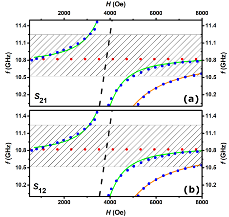
Right bottom of Fig. 4 reveals another ultrastrong MPC expressed in orange curve. We design another experiment to understand the nature of the coupling. Note that the magnon mode and photon mode are provided by the YIG cylinder simultaneously [46, 47, 48].
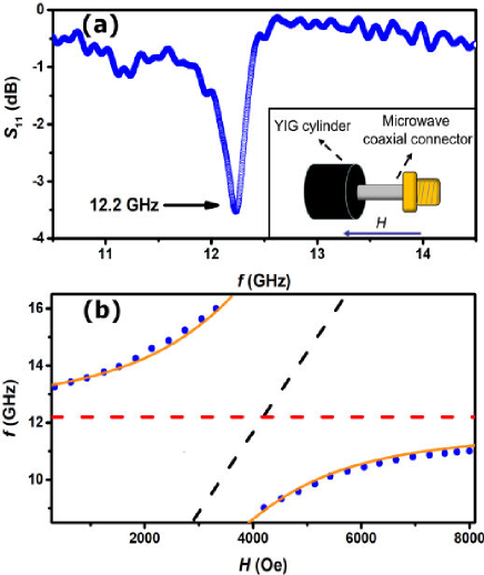
As shown in the inset of Fig. 5(a), a microwave coaxial connector connected to the VNA is used to feed microwaves for the YIG cylinder. In this system, YIG cylinder is regarded as a microwave cavity itself and the first eigenmode is discovered at 12.2 GHz which is evident from Fig. 5(a). Correspondingly, this eigenmode could be regarded as the photon mode to interact with FMR mode. Subsequently, we applied static magnetic field on the YIG to discover the variation of the microwave reflection coefficients . As anticipated, we observed an anticrossing phenomenon caused by FMR mode and photon mode of the YIG. In Fig. 5(b) details of the spectrum of the coupling in the frequency versus applied static magnetic field, blue dots stand for the experiment data, black and red dashed lines represents FMR mode and photon mode of YIG cylinder, respectively. The coupling curves could be fit by two-mode model also:
| (5) |
where is the photon frequency of the defect mode, are frequencies of the coupled resonances and is the coupling strength with a value of 4 GHz. As shown in Fig. 5, is described by orange curve. It is observed from the results that polarization mode is adaptive for orange solid line as shown in Fig. 4.
IV SUMMARY
In summary, we introduces a magnetic point defect by replacing a copper cylinder with a single crystal YIG cylinder, which is not located on the axis of symmetry in the 2D simple cubic metal PCs, breaking the spatial symmetry of the system. A defect mode at a frequency of 10.8 GHz in the bandgap could be found. This defect mode can be regarded as a photon mode that couples with the FMR mode of YIG, with a coupling strength of 1.18 GHz. As the coupling efficiency exceeding 10%, reaching up to 10.9%, the coupling can be considered as an ultrastrong MPC. Furthermore, the coupling displays strong nonreciprocity, enabling unidirectional microwave transmission within the bandgap of PCs. This study contributes to a better understanding of the magnetic defect in PCs, which is of great significance for exploring the fundamental principles and applications of PCs and for developing new microwave devices. In particular, it sheds some light on providing new ideas and directions for devices used in the field of microwave filtering.
V Acknowledgements
This work is supported by the National Natural Science Foundation of China (NSFC) (No. 12174165) and Natural Science Foundation of GanSu Province for Distinguished Young Scholars (No. 20JR10RA649).
References
- Zhang et al. [2016] X. Zhang, C.-L. Zou, L. Jiang, and H. X. Tang, Sci. Adv. 2, e1501286 (2016).
- Harder and Hu [2018] M. Harder and C.-M. Hu, Solid State Phys. 69, 47 (2018).
- Bhoi and Kim [2019] B. Bhoi and S.-K. Kim, Solid State Phys. 70, 1 (2019).
- Hu [2020] C.-M. Hu, Solid State Phys. 71, 117 (2020).
- Zare Rameshti et al. [2022] B. Zare Rameshti, S. Viola Kusminskiy, J. A. Haigh, K. Usami, D. Lachance-Quirion, Y. Nakamura, C.-M. Hu, H. X. Tang, G. E. Bauer, and Y. M. Blanter, Phys. Rep. 979, 1 (2022).
- Soykal and Flatté [2010a] Ö. O. Soykal and M. E. Flatté, Phys. Rev. Lett. 104, 077202 (2010a).
- Soykal and Flatté [2010b] Ö. O. Soykal and M. E. Flatté, Phys. Rev. B 82, 104413 (2010b).
- Huebl et al. [2013] H. Huebl, C. W. Zollitsch, J. Lotze, F. Hocke, M. Greifenstein, A. Marx, R. Gross, and S. T. B. Goennenwein, Phys. Rev. Lett. 111, 127003 (2013).
- Zhang et al. [2014] X. Zhang, C.-L. Zou, L. Jiang, and H. X. Tang, Phys. Rev. Lett. 113, 156401 (2014).
- Harder et al. [2018] M. Harder, Y. Yang, B. M. Yao, C. H. Yu, J. W. Rao, Y. S. Gui, R. L. Stamps, and C.-M. Hu, Phys. Rev. Lett. 121, 137203 (2018).
- Bhoi et al. [2019] B. Bhoi, B. Kim, S.-H. Jang, J. Kim, J. Yang, Y.-J. Cho, and S.-K. Kim, Phys. Rev. B 99, 134426 (2019).
- Hyde et al. [2016] P. Hyde, L. Bai, M. Harder, C. Match, and C. M. Hu, Appl. Phys. Lett. 109, 152405 (2016).
- Bai et al. [2017] L. Bai, M. Harder, P. Hyde, Z. Zhang, C.-M. Hu, Y. P. Chen, and J. Q. Xiao, Phys. Rev. Lett. 118, 217201 (2017).
- Li et al. [2018] J. Li, S.-Y. Zhu, and G. S. Agarwal, Phys. Rev. Lett. 121, 203601 (2018).
- Wang et al. [2019] Y.-P. Wang, J. W. Rao, Y. Yang, P.-C. Xu, Y. S. Gui, B. M. Yao, J. Q. You, and C.-M. Hu, Phys. Rev. Lett. 123, 127202 (2019).
- Zhang et al. [2019a] X. Zhang, K. Ding, X. Zhou, J. Xu, and D. Jin, Phys. Rev. Lett. 123, 237202 (2019a).
- Zhang et al. [2021] C. Zhang, C. Jia, Y. Shi, C. Jiang, D. Xue, C. K. Ong, and G. Chai, Phys. Rev. B 103, 184427 (2021).
- Shi et al. [2021] Y. Shi, C. Zhang, C. Jiang, C. K. Ong, and G. Chai, Appl. Phys. Lett. 119, 132403 (2021).
- Wang et al. [2018] Y.-P. Wang, G.-Q. Zhang, D. Zhang, T.-F. Li, C.-M. Hu, and J. Q. You, Phys. Rev. Lett. 120, 057202 (2018).
- Bai et al. [2015] L. Bai, M. Harder, Y. P. Chen, X. Fan, J. Q. Xiao, and C.-M. Hu, Phys. Rev. Lett. 114, 227201 (2015).
- Bhoi et al. [2014] B. Bhoi, T. Cliff, I. S. Maksymov, M. Kostylev, R. Aiyar, N. Venkataramani, S. Prasad, and R. L. Stamps, J.Appl.Phys. 116, 243906 (2014).
- Zhang et al. [2017] D. Zhang, W. Song, and G. Chai, J. Phys. D 50, 205003 (2017).
- Shi et al. [2019] Y. Shi, D. Zhang, C. Zhang, C. Jiang, and G. Chai, J. Phys. D 52, 305003 (2019).
- Zhang et al. [2019b] C. Zhang, Y. Shi, W. Zhang, C. Jiang, and G. Chai, Appl. Phys. Lett. 115, 022407 (2019b).
- Yablonovitch [1987] E. Yablonovitch, Phys. Rev. Lett. 58, 2059 (1987).
- John [1987] S. John, Phys. Rev. Lett. 58, 2486 (1987).
- Joannopoulos et al. [2008] J. D. Joannopoulos, S. G. Johnson, J. N. Winn, and R. D. Meade, Photonic Crystals Molding the Flow of Light (Princeton University Press, Princeton, 2008).
- Wang et al. [2008] Z. Wang, Y. D. Chong, J. D. Joannopoulos, and M. Soljačić, Phys. Rev. Lett. 100, 013905 (2008).
- Wang et al. [2009] Z. Wang, Y. Chong, J. D. Joannopoulos, and M. Soljačić, Nature 461, 772 (2009).
- Liu et al. [2008] S. Liu, W. Chen, J. Du, Z. Lin, S. T. Chui, and C. T. Chan, Phys. Rev. Lett. 101, 157407 (2008).
- Poo et al. [2011] Y. Poo, R.-x. Wu, Z. Lin, Y. Yang, and C. T. Chan, Phys. Rev. Lett. 106, 093903 (2011).
- Lian et al. [2012] J. Lian, J.-X. Fu, L. Gan, and Z.-Y. Li, Phys. Rev. B 85, 125108 (2012).
- Poo et al. [2012] Y. Poo, R.-x. Wu, S. Liu, Y. Yang, Z. Lin, and S. T. Chui, Appl.Phys.Lett. 101, 081912 (2012).
- Skirlo et al. [2015] S. A. Skirlo, L. Lu, Y. Igarashi, Q. Yan, J. Joannopoulos, and M. Soljačić, Phys. Rev. Lett. 115, 253901 (2015).
- Liu and Houck [2017] Y. Liu and A. A. Houck, Nat. Phys. 13, 48 (2017).
- Serga et al. [2010] A. A. Serga, A. V. Chumak, and B. Hillebrands, J. Phys. D 43, 264002 (2010).
- Kittel [1948] C. Kittel, Phys. Rev. 73, 155 (1948).
- Chikazumi [1997] S. Chikazumi, Physics of Ferromagnetism (Oxford University, New York, 1997).
- Fu et al. [2010] J.-X. Fu, R.-J. Liu, and Z.-Y. Li, Appl.Phys.Lett. 97, 041112 (2010).
- So et al. [1995] P. So, S. M. Anlage, E. Ott, and R. N. Oerter, Phys. Rev. Lett. 74, 2662 (1995).
- Dietz et al. [2009] B. Dietz, T. Friedrich, H. L. Harney, M. Miski-Oglu, A. Richter, F. Schäfer, J. Verbaarschot, and H. A. Weidenmüller, Physical Review Letters 103, 064101 (2009).
- Dietz et al. [2006] B. Dietz, T. Guhr, H. L. Harney, and A. Richter, Physical Review Letters 96, 254101 (2006).
- Dietz et al. [2019] B. Dietz, T. Klaus, M. Miski-Oglu, A. Richter, and M. Wunderle, Physical Review Letters 123, 174101 (2019).
- Dietz et al. [2015] B. Dietz, T. Klaus, M. Miski-Oglu, A. Richter, M. Bischoff, L. von Smekal, and J. Wambach, Physical Review Letters 115, 026801 (2015).
- Niemczyk et al. [2010] T. Niemczyk, F. Deppe, H. Huebl, E. Menzel, F. Hocke, M. Schwarz, J. Garcia-Ripoll, D. Zueco, T. Hümmer, E. Solano, et al., Nat.Phys. 6, 772 (2010).
- Zare Rameshti et al. [2015] B. Zare Rameshti, Y. Cao, and G. E. W. Bauer, Phys. Rev. B 91, 214430 (2015).
- Bourhill et al. [2016] J. Bourhill, N. Kostylev, M. Goryachev, D. L. Creedon, and M. E. Tobar, Phys. Rev. B 93, 144420 (2016).
- Krupka et al. [2021] J. Krupka, A. Pacewicz, B. Salski, P. Kopyt, J. Bourhill, M. Goryachev, and M. Tobar, J. Magn. Magn. Mater. 521, 167536 (2021).