Egalitarian ORAM: Wear-Leveling for ORAM
Abstract
While non-volatile memories (NVMs) provide several desirable characteristics like better density and comparable energy efficiency than DRAM, DRAM-like performance, and disk-like durability, the limited endurance NVMs manifest remains a challenge with these memories. Indeed, the endurance constraints of NVMs can prevent solutions that are commonly employed for other mainstream memories like DRAM from being carried over as-is to NVMs. Specifically, in this work we observe that, Oblivious RAM (ORAM) primitive, the state-of-art solution to tackle memory bus side channel vulnerability, while widely studied for DRAMs, is particularly challenging to implement as-is for NVMs as it severely affects endurance of NVMs. This is so, as the inherent nature of ORAM primitive causes an order of magnitude increase in write traffic and furthermore, causes some regions of memory to be written far more often than others. This non-uniform write traffic as manifested by ORAM primitive stands to severely affect the lifetime of non-volatile memories (1% of baseline without ORAM) to even make it impractical to address this security vulnerability.
To address this challenge, in this work, we propose Egalitarian ORAM (E-ORAM), which discusses an ORAM design for NVMs while achieving close to ideal lifetime of non-volatile memory. To do so, we observe that the inherent nature of ORAM primitive can be exploited to design a wear-levelling algorithm which spreads the additional write traffic generated by ORAM more uniformly across the entire non-volatile memory space. We demonstrate that in comparison to existing state-of-art wear-levelling algorithm which in presence of ORAM can only attain 2.8% lifetime, proposed E-ORAM design attains approximately 91% lifetime allowing it to perform orders of magnitude more reads/writes before system failure while introducing less than 0.02% performance overhead.
1 Introduction
Memory system innovations continue to be fueled by the ever-present and ever-growing demands for increased memory capacity and bandwidth. One such innovation is Non-volatile memories (NVMs) (including PCM [22], STTRAM [20], and ReRAM [39]). These memories offer several desirable characteristics like better density and comparable energy efficiency than DRAM, DRAM-like performance, and disk-like durability. Consequently, NVMs potentially stand to play an important role in future memory systems.
However, deploying NVMs widely is not devoid of challenges. One of the challenges associated with NVMs is the limited endurance NVMs manifest, that is, the physical properties of memory cells in NVMs dictate a limit on number of writes to the memory cell (typically between to [13]). Beyond this limit, the memory cell may lose the ability to change state causing data errors. This in turn can lead to system failure when enough memory lines reach endurance limit. This happens when the number of spare memory lines is lower than memory lines that have incurred more writes than dictated by the endurance limit.
We observe in this work that the endurance constraints of NVMs make it impractical to carry-over solutions which are widely studied for mainstream memories like DRAM to NVMs. Specifically, we observe this to be true in the context of ORAM primitive, which is typically studied to address memory bus side channel vulnerability for DRAM systems. To exploit this vulnerability, an attacker taps the memory bus to learn the memory address trace of the program. Prior work [40] has shown that even in presence of data encryption, an attacker can learn sensitive information about the program simply by observing the memory address trace of the program. To tackle this vulnerability, the ORAM primitive accesses an order of magnitude more memory locations on each memory access and further shuffles memory on each access. As such, under ORAM, any memory address trace is computationally indistinguishable from any other address trace of the same length.
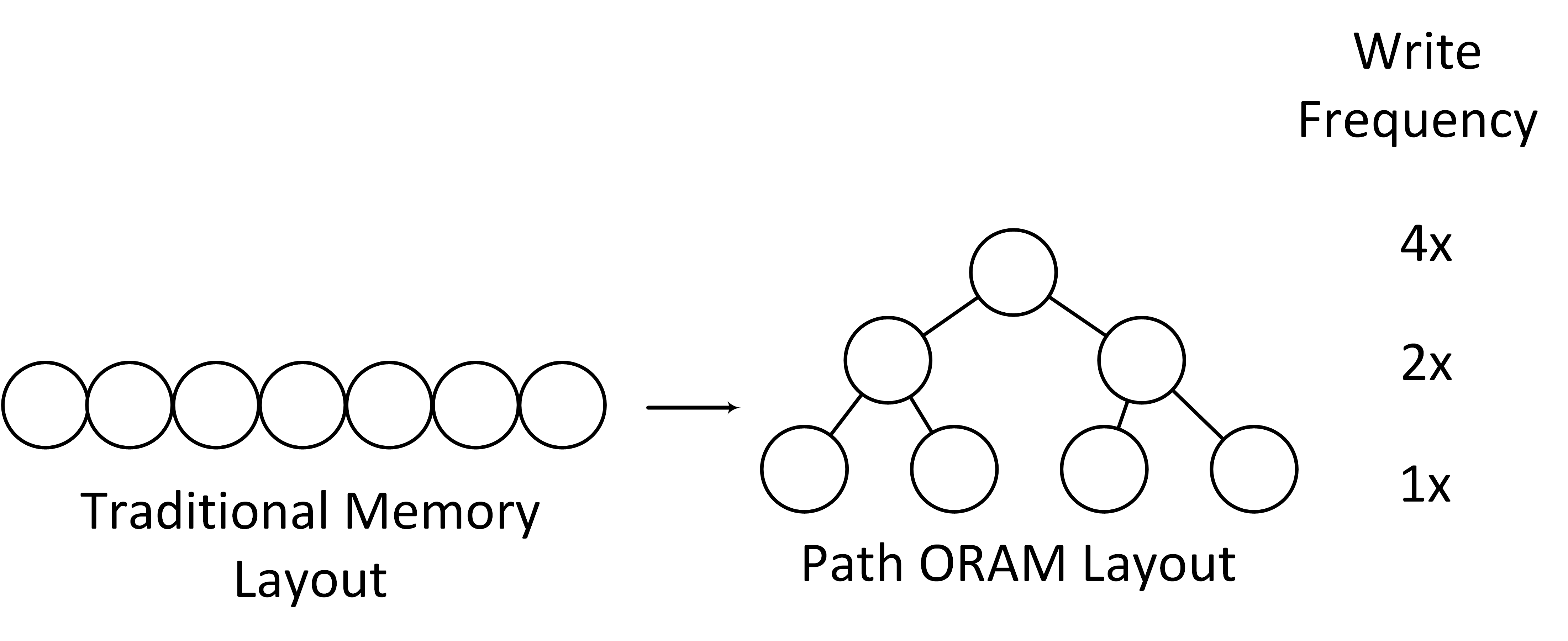
However, this very nature of ORAM primitive while effective in addressing memory bus side channel severely affects endurance of NVMs. This is so, as memory lines are less likely to reach endurance limit in presence of uniform memory write traffic (write traffic uniformly distributed across the entire memory space) as compared to non-uniform memory traffic where few memory lines are written more often than others. The most state-of-art implementation of ORAM, Path-ORAM [37], however, manifests exponential write distribution severely affecting NVM endurance. This happens as Path-ORAM organizes memory as a binary tree and on each memory access reads and writes a entire path in this tree. Fig. 1 shows the memory layout of Path ORAM. As shown in Fig. 1, Path ORAM arranges memory as a balanced binary tree structure, where each node is written equally at the same level. From the root to leaf, the expected number of writes to each node decreases exponentially. This leads to an exponential write distribution, where nodes closer to the root node in the memory tree are written far often than leaf nodes in the tree. This non-uniform write traffic as manifested by ORAM primitive stands to severely affect the lifetime of non-volatile memories (1% of baseline without ORAM) so as to even make it impractical to address memory bus side channel for NVMs.
Note that, prior works [28] have observed that even typical application behavior can exacerbate the endurance constraints of NVMs as they manifest non-uniformity in write traffic. As such, to address this, several wear-levelling algorithms have been proposed by prior works [7, 11, 28, 14, 5]. The tenet of these algorithms is to spread application write traffic as uniformly as possible across the non-volatile memory space by employing memory line remapping as necessary. However, as we show in this work, the ORAM primitive severely stresses these prior solutions and as such, existing state-of-art wear-levelling algorithm [28] in presence of ORAM can only attain 2.8% lifetime.
To tackle NVM endurance constraints while addressing memory bus side channel vulnerability with ORAM primitive, in this work we make the observation that the inherent nature of ORAM primitive can be exploited to design a wear-levelling algorithm which directly tackles the endurance pressure of ORAM primitive. Specifically, while the Path-ORAM [37] implementation of ORAM primitive by its very nature manifests an exponential write distribution, it does so in a deterministic manner. That is, the expected number of writes to a given memory line is statically known depending on where in the Path-ORAM tree the memory line belongs (e.g., root note is written twice as much as its children). We use this information provided by the inherent nature of the ORAM primitive to augment a state-of-art wear-levelling algorithm, Start-Gap [28] and make it ORAM primitive aware. We term this ORAM design for NVMs which directly tackles NVM endurance constraints, E-ORAM. We show how our proposed design can attain 91% lifetime and perform orders of magnitude more reads/writes before system failure while introducing less than 0.02% performance overhead.
The contributions of this work are:
-
•
We observe in this work that the endurance constraints of non-volatile memories (NVMs) make it impractical to implement Oblivious-RAM (ORAM) primitive for NVMs, a state-of-art defense against memory-bus side channel vulnerability, as it leads to a system lifetime of 1% of baseline system without ORAM.
-
•
To address this challenge, we make the observation that the inherent nature of ORAM primitive can be exploited to design a wear-levelling algorithm which directly tackles the endurance pressure of ORAM primitive.
-
•
We harness the above observation in our proposed ORAM design for NVMs, termed, E-ORAM, in which we augment a state-of-art wear-levelling algorithm, Start-Gap [28] with ORAM primitive awareness.
-
•
We demonstrate that while state-of-art wear-levelling algorithm [28] in presence of ORAM can only attain 2.8% lifetime, proposed E-ORAM design attains 91% lifetime allowing it to perform orders of magnitude more reads/writes before system failure while introducing less than 0.02% performance overhead.
2 Background and Motivation
In this section, we will introduce necessary background to understand this work. To that end, first, we discuss background on non-volatile memories (NVMs) and the endurance limit they manifest followed by a discussion of Start-Gap [28], a state-of-the-art wear-leveling mechanism. Then, we discuss the threat model we assume in this work. After that, we provide background on the most state-of-art implementation of ORAM primitive, Path-ORAM [37]. Finally, we discuss how the Path-ORAM algorithm stresses the endurance of NVMs.
2.1 Non-Volatile Memories
Emerging non-volatile memories (NVMs), including PCM, STTRAM and ReRAM [22, 20, 39] can provide several desirable properties like high density, non-volatility and an access latency close to DRAM [31]. Further, as NVMs are byte-addressable (they provide load/store interface[43]) and non-volatile, they can make it possible to host recoverable data structures in NVMs instead of accessing them from disk at steeper performance and energy costs.
While NVMs have several desirable characteristics making their inclusion in future memory systems possible, several challenges remain. One of the challenges is about their limited write endurance. A typical write endurance ranges from to [13] due to physical properties of NVM memory cells. Once the limit is passed, data errors may raise because memory cells may no longer be able to change their states, which can in turn lead to system failure if sufficient memory lines reach endurance limit. This happens when the number of spare memory lines is lower than memory lines that have incurred more writes than dictated by the endurance limit.
Several prior works have been proposed to solve the limited write endurance problem of NVMs. These approaches can typically be categorized into write reduction techniques and wear-leveling techniques. Write reduction techniques focuses on reducing the number of NVM writes. For example, Qureshi et al. [29] proposed using PCM as an extended storage of DRAM. Gogte et al. [14] proposed using software management system to migrate frequently accessed pages from NVM to DRAM. On the other hand, wear-leveling techniques focus on spreading memory writes uniformly across all NVM memory space. We discuss several prior wear-leveling techniques and compare them to our proposed work in Section 8.
2.2 Baseline Start-Gap
Start-Gap divides NVMs into equal-sized groups. Each group reserves an empty cache line. The CPU maintains a start register and a gap register for each group. Each memory address will be translated based on the value of start and gap registers. The CPU maintains a counter for each group to store the number of writes to that group so far. Upon the counter reaching a threshold, the gap register will be updated, so one of the cache lines in that group will be mapped to a new address. Once the gap register finishes looping through the entire group, the start register will be updated. The algorithm also employs an address randomizer which maps logical addresses to intermediate addresses before further translating them to physical addresses with start and gap registers.
2.3 Threat Model
We assume a secure processor where applications can harness isolated execution [23]. We assume that the execution of an application along with its data in the processor structures (registers, caches, on-chip networks) are secure and isolated from other applications. We assume a system where NVM is employed as the main memory. We assume the NVM is untrusted and to defend against cold (re)boot attacks [17], data is encrypted in memory. Further, we also assume an adversary with physical access to the computers and as such, capable of probing the off-chip memory bus [10] to learn the address trace and data being communicated between the processor and NVM. Prior works [40] have shown that even with encrypted data, an attacker can ascertain sensitive secrets about an application simply by observing the address trace of the application. We assume prior solutions for mitigating page-fault side-channel [2, 8]. Finally, prior works which address other important vulnerabilities such as power [19], thermal [27], program execution time [41] side-channels, and leaks via communication patterns over the network [35, 26] do exist and we assume addressing these vulnerabilities to be outside the scope of this paper.
2.4 Path Oblivious RAM
Oblivious RAM [15], is a cryptographic primitive which makes a memory access trace computationally indistinguishable from a random access trace of the same length. While several realizations of this primitive have been proposed to date [9, 16, 16, 21], a backbone for them is Path ORAM [37], the most practical implementation of ORAM primitive. In this section, we provide relevant background on Path-ORAM algorithm (henceforth simply referred to as ORAM).
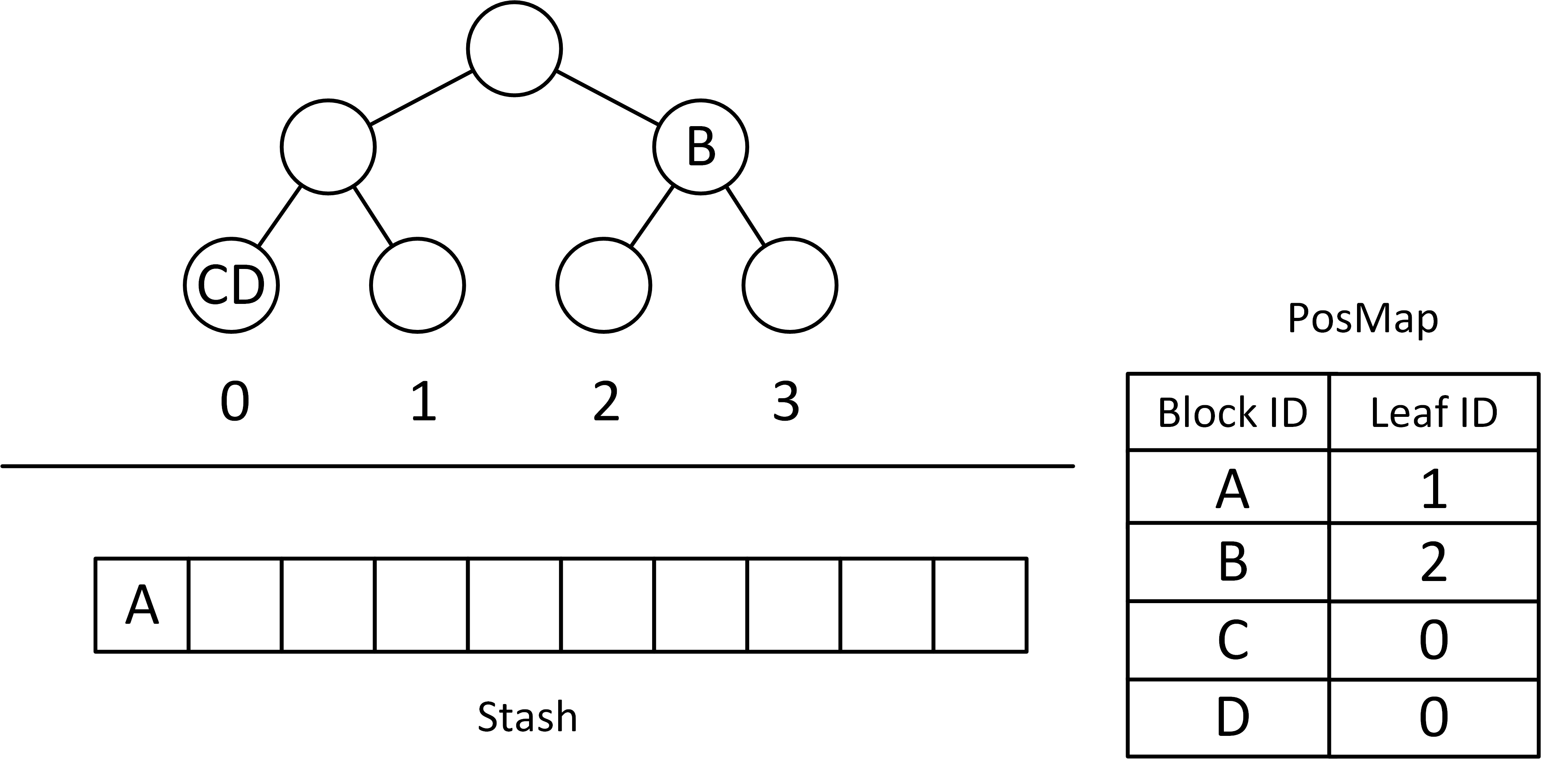
ORAM arranges memory into a balanced binary tree structure, and each node in the ORAM tree contains a fixed number of slots where each slot can store a single data block (typically a single cache block). ORAM tree has associated with it a utilization factor, referring to the fraction of actual data blocks over total blocks in the tree. Non-data blocks are filled with dummy blocks. Each real data block has a corresponding leaf ID, which indicates that this data block is stored on the path from the root node to the leaf corresponding to the leaf ID. This mapping information is maintained by a position-map (PosMap) structure. All blocks, regardless of real data block or dummy block, are encrypted before being stored into memory. Encryption metadata, such as block ID (the slot within each node), leaf ID, as well as encryption counter, are also maintained by the ORAM tree. ORAM also uses an on-chip structure, stash, to aid in its working.
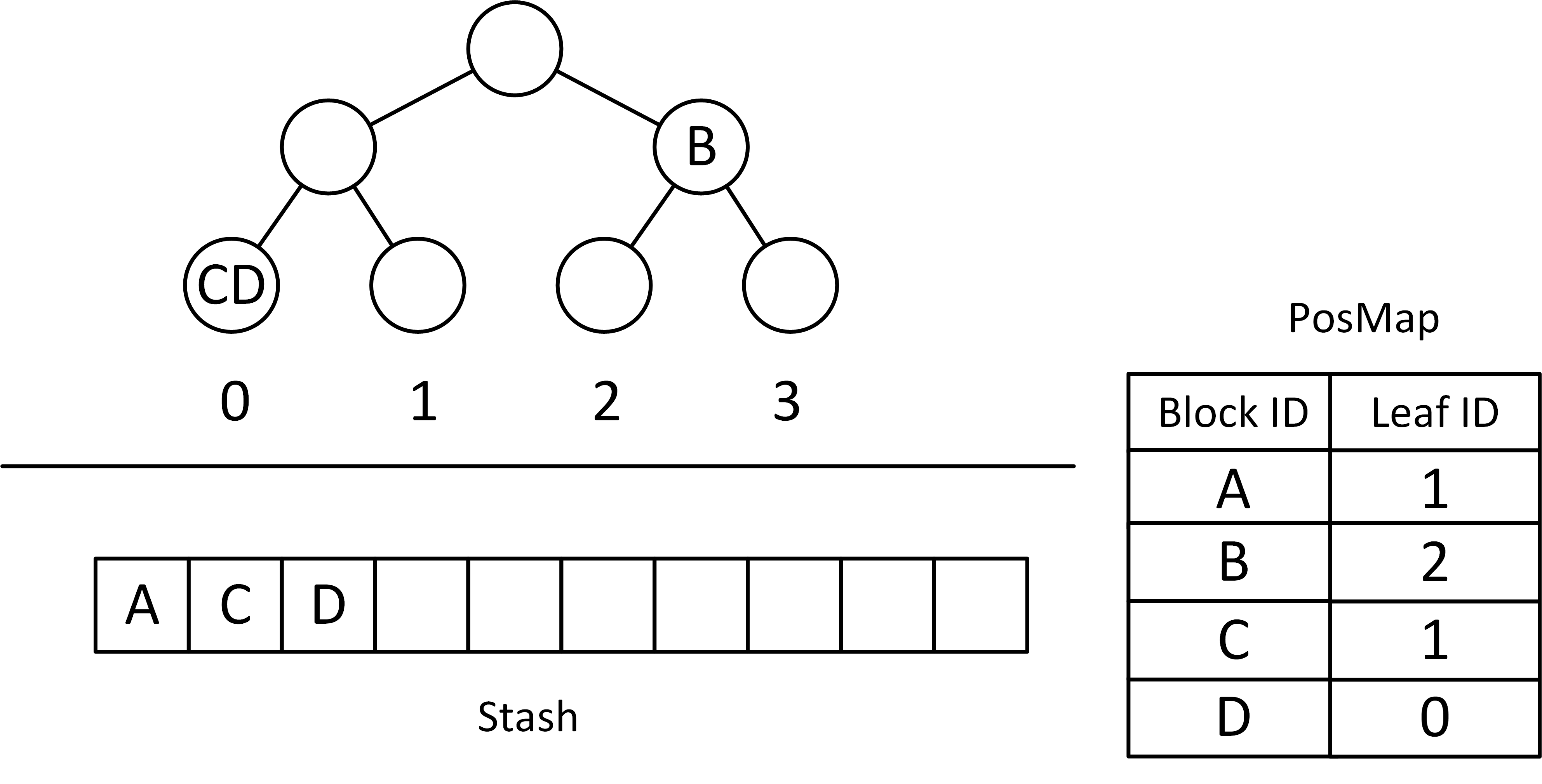
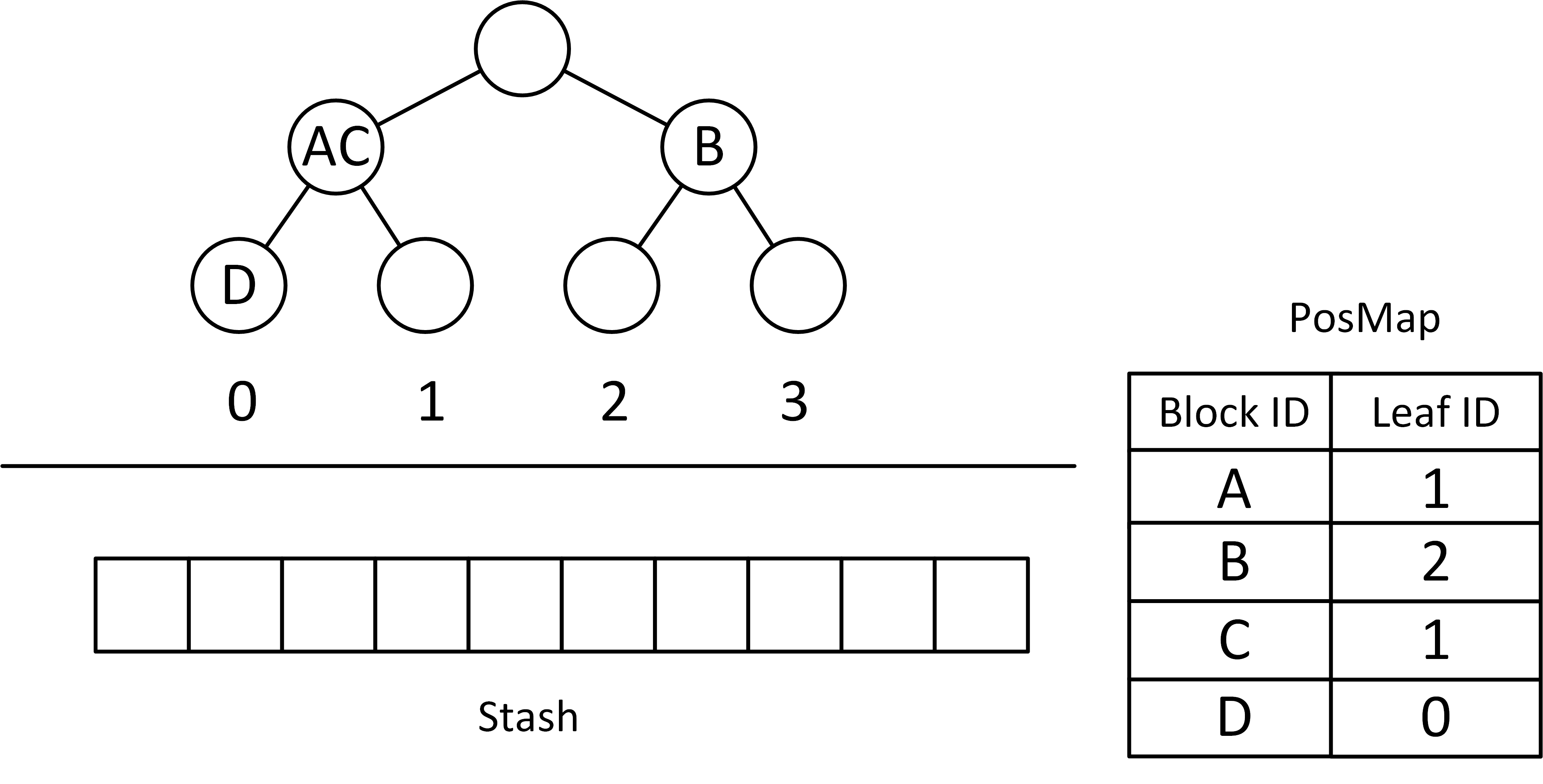
Next, we use a 3-level ORAM tree in Fig. 2 as an example to show the workings of ORAM. Consider the scenario when the application issues a read request to data block C. Fig 2a shows the initial status of the ORAM tree, stash and PosMap. On receiving the read request, the algorithm first looks up PosMap to find the leaf ID that the block C corresponds to, which is 0 (leaf nodes in the tree are labeled from 0 to 3). Per the ORAM primitive, each program memory access is translated to a read and write of a path from root node to the leaf associated with the block. As such, the algorithm proceeds to read and write path to leaf 0 as depicted in Fig. 2a. To do so, ORAM issues read operations to all nodes along the path from the root node to leaf 0 and loads real data blocks (C and D), into the stash. Post the path read the needed data block is in the stash and is decrypted and supplied to the processor. At this moment, ORAM will remap block C to a newly generated random leaf ID, which is 1 in this case, as shown in Fig. 2b. This remapping confirms that the next access to block C accesses a completely random path in the ORAM tree. Finally, ORAM writes back the same path it read from, draining re-encrypted blocks from the stash as deep as possible. In this example, block D is mapped to leaf 0, which is fine to be pushed into leaf 0. Block A and C are mapped to leaf 1, so the deepest node they can be stored in is the parent node of leaf 0 and 1.
By re-mapping the data block each time it is accessed to a random leaf, ORAM allows for a completely new set of blocks are accessed each time the same data block is accessed. This, along with the fact that each access causes re-encryption of all accessed blocks helps hide address trace of the application.
2.5 Challenges in realizing ORAM for NVMs
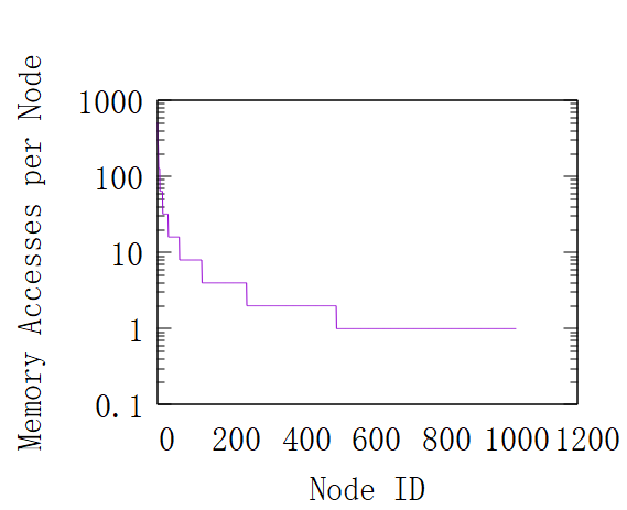
We discuss in this section how, by its very nature, the ORAM primitive severely stresses endurance of NVMs. This is so, as ORAM manifests a skewed write access pattern as shown in Figure 3. As discussed in section 2.4, memory is organized as a binary tree with ORAM and memory accesses are transformed into read/writes of paths in the tree. This translates to the scenario as depicted in Figure 3, where the nodes closer to the root (lower Node-ID) are written far more often than nodes closer to leaf nodes (higher Node-ID). From the root node, its two child nodes are accessed with equal probability due to the nature of ORAM, so each child node is accessed with half frequency of the root node. This access property applies to all nodes, which causes the number of writes per node in level to decrease exponentially as the level increases linearly. Therefore, we see that leaf nodes are written far less frequently than the root node, while occupying half of the tree.
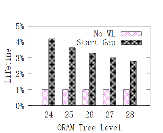
We depict the stress ORAM’s write distribution causes on NVM endurance in Fig. 4 (please see Section 7 for details on our methodology). In Fig. 4 we depict system lifetime for a NVM that implements ORAM. We define system lifetime to be:
As every program memory access in ORAM translates to read and write of a path in ORAM tree (as explained in Section 2.4), in the above equation, the numerator calculates the total reads/writes to NVM which implements ORAM before system failure. The denominator calculates the ideal number of reads/writes possible to memory with perfect wear-levelling, where Wmax refers to the endurance of a cache line, e.g., the number of writes to a cache line before it fails. We chose Wmax to be . We consider a NVM failure and consequent system failure when more than 1% of cache lines have reached endurance limit, similar to a mechanism used in [14]. Further, we show both the lifetime without wear-leveling and in presence of state-of-art wear-levelling solution, Start-Gap [28], As Fig. 4 depicts, both configurations achieve less than 4% lifetime and furthermore, lifetime drops with larger ORAM tree size (= larger NVM memory size). Emerging NVMs are deployed in terabytes [1], which would translate to a very large tree, e.g., 32-level tree. As a result, it is expected that the lifetime will be poor. This makes it impractical to implement ORAM for NVMs and consequently, impractical to address memory bus side channel for NVMs.
3 Egalitarian ORAM - Insight
In this section, we propose the inspiration for E-ORAM, our proposed wear-levelling algorithm to tackle endurance pressure of ORAM primitive for NVMs.
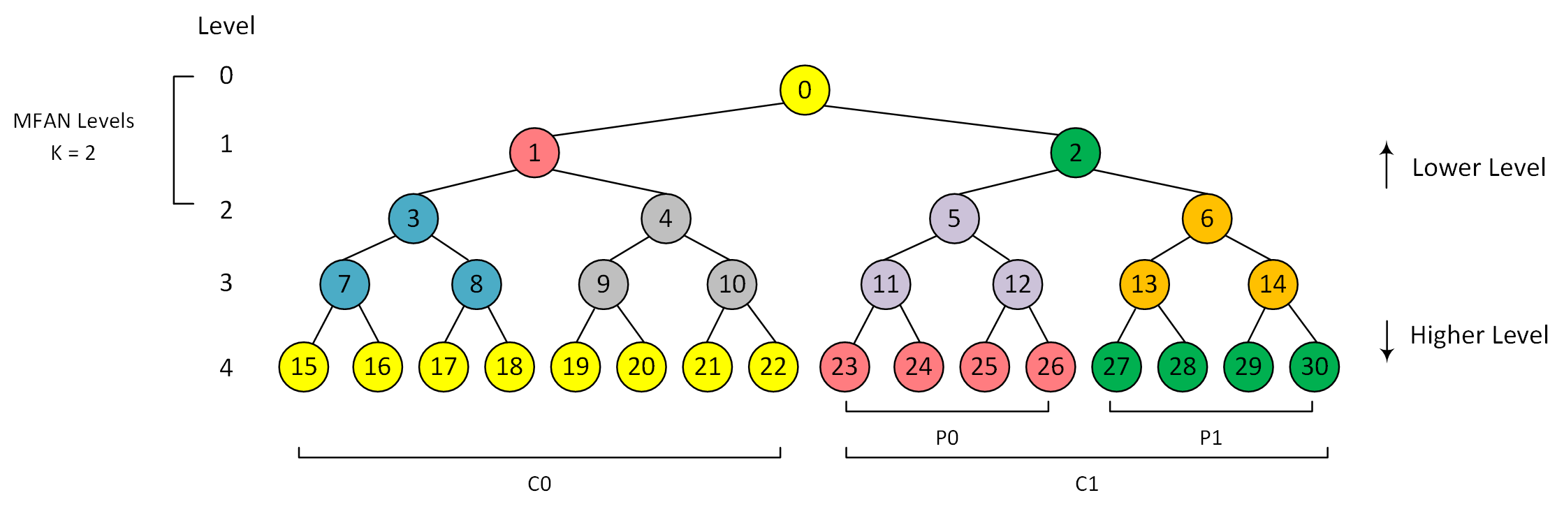
Fig. 5 shows a simple 5-level ORAM tree with 31 nodes. In this example, we label each node with a unique node ID. Nodes closer to the root node are assigned smaller node IDs. ORAM accesses to this tree result in a total of node reads and writes, for each of the 5 levels. However, since levels 0 to 4 contain 1, 2, 4, 8, 16 nodes respectively, the number of reads and writes to each of the nodes in these levels are , , , , respectively. The goal of an ideal wear-leveling algorithm would be to confirm that each of the 31 physical node locations see the same number of writes, i.e., . This goal can be achieved by periodically remapping logical nodes to different physical nodes so that the writes are as close to uniformly distributed as possible. To minimize performance overheads from the re-mappings, we have to ensure that there are (i) only as many re-mappings as necessary and (ii) the indirection costs associated with routing accesses to logical nodes to the appropriate physical nodes must be kept low.
E-ORAM is based on the observation that nodes in levels 0, 1, and 2 are accessed more frequently than the ideal and the remaining nodes in levels 3 and 4 are accessed less frequently. If we were to form a group with the root node from level 0 and eight nodes from level 4 and assume ideal wear-leveling within the group, we can achieve average number of writes per node of , coming within 3% of the ideal (). Similarly, a group formed with one node from level 1 and four nodes from level 4 comes within 7% of the ideal. As we discuss in detail later, continuing this process of grouping one frequently written node (referred to as the Most Frequently Accessed Node, MFAN, henceforth) from a level close to the root with some partner nodes (referred to as the Partner Nodes, PNs, henceforth) from a relatively infrequently written level and wear-leveling within each of the groups can get us very close to ideal wear-leveling. We define such in-group wear-leveling as MFAN movement.
Note that prior state-of-art wear-levelling solution, Start-Gap [28], also proposed breaking down memory space into groups and performing wear-levelling in each group. However, we augment this basic idea in several important ways. When handling ORAM’s exponential write distribution, Start-Gap falls short due to its design choice of breaking down the memory addresses into randomized, fixed-sized, wear-leveling groups. With fixed sized groups, if a group happens to contain a very heavily written ORAM node (say the root node), then that group is likely to wear out much sooner than other groups that contain only relatively infrequently written nodes (say only the leaf nodes). This imbalance limits the lifetime achieved with Start-Gap on ORAM-style access patterns. However, one of the advantages of ORAM-style access pattern is that given its randomization and the binary-tree arrangement, the fraction of total writes incurred by each node is known apriori just by knowing the size of the ORAM tree. With this knowledge, it is possible to statically partition the ORAM tree into groups such that average number of writes per node incurred across all the groups is similar. Our central idea is to form variable sized groups instead of fixed-size groups in an ORAM primitive aware manner (unlike randomized in Start-Gap). This design choice allows very frequently written nodes like the root node to be grouped with a large number of infrequently nodes and reduce the average number of writes per node. However, having variable sized groups creates challenges in keeping track of which nodes belong to which groups and the wear-leveling movements within each group. We discuss our solutions to these challenges next.
4 Egalitarian ORAM
In this section, we discuss two parts E-ORAM is composed of: 1) the partition algorithm to group ORAM tree nodes and 2) the node remapping algorithm, which efficiently remaps nodes within the same group.
4.1 Static group partitioning
The first part of E-ORAM involves a static partition of the ORAM tree. We partition the ORAM tree into many groups with the following goals: (i) the average number of writes per node in each group approaches the average number of writes per node in the entire tree and (ii) within each group, there exists exactly one node being written more frequently than all other nodes (MFAN as defined in section 3), and all other nodes are expected to be accessed equally (partner nodes, as defined in section 3). This goal is to simplify the hardware implementation of E-ORAM as we will explain in §4.2.1.
Given the two principles, we can design an algorithm to partition our ORAM tree. For an ORAM tree with levels (with level 0 being the root node), we will choose a threshold level, , such that all nodes belonging to levels to are grouped with level , which is the leaf level. Exactly how we choose the value of will be described later in this section. Then, nodes in the leaf level are further divided into equal-size chunks, and assign them with chunk IDs, defined as , where . Nodes in are paired with nodes in level . Use Fig. 5 as an example, we will choose as the first step, and then divide nodes in level 4 into 2 chunks, and . nodes (yellow nodes in level 4) are grouped with the root node (also yellow), while the two nodes in level 1 (nodes 1 and 2, red and green respectively) are grouped with half of the nodes in each (red and green respectively). We denote each subset nodes in as Parts and assign them with Part IDs. So far, we have formed groups for nodes in level 0 and 1 and level 4, that leaves the nodes in levels 2 and 3 to be grouped. As can be seen from Fig. 5, the nodes in levels 2 and 3 can be viewed as four separate, smaller ORAM trees (in blue, grey, purple, and orange colors). Our partitioning strategy can be recursively applied to these intermediate, smaller ORAM trees until the entire larger tree has been partitioned. One important characteristic in the groups formed by our algorithm is that each group has one MFAN (most frequently accessed node) and the rest of the partner nodes all belong to the same, less frequently accessed level. With this characteristic, we define as the highest level that contains MFAN nodes, called MFAN level. In this example, . This value is crucial when discussing how to trigger MFAN movement in section 4.2.2 and performance overhead in section 5.1.
The last aspect that we have not yet discussed is how to choose an appropriate threshold level . Assuming perfect intra-group wear-leveling, we experimented with different values of . We found that threshold level value of gives us the lowest number of writes per node in the most vulnerable group, making it the optimal threshold level value in our algorithm.
4.2 Node Remapping
While the groups are decided statically, at runtime, the wear-leveling algorithm has to perform the following actions: (i) decide when to perform the MFAN movements for each of the groups and (ii) accurately maintain the mapping of logical node IDs and corresponding physical locations accounting for all the MFAN movements performed. Apart from being functionally correct, we also aim to perform the above two actions with the high performance and low storage overheads. Next, we describe how we perform both actions.
4.2.1 MFAN Movement Algorithm
In this section, we will discuss how MFAN movements are handled. Notice for a group , when an MFAN movement occurs, we need to perform a data swap between MFAN and one of its partner nodes. We will use Fig. 5 as an example to illustrate the MFAN movement algorithm.
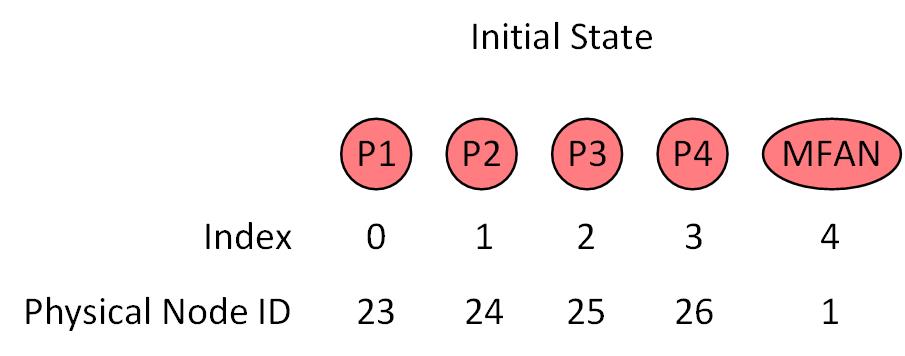
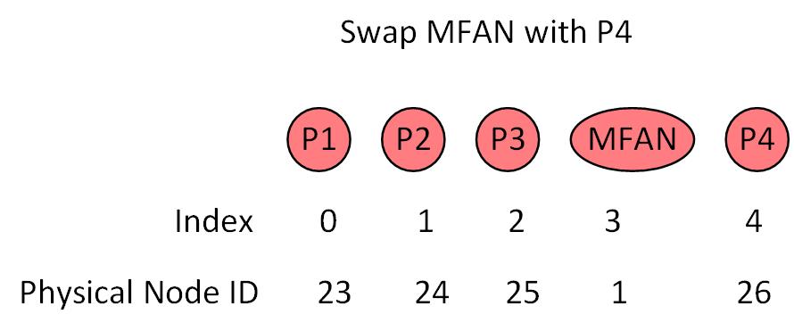
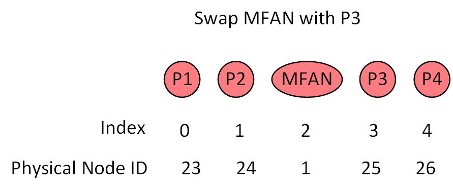
Consider the red group, it has fives nodes in total: the MFAN (node 1 in level 1) and four partner nodes (P1, P2, P3, P4, nodes 23, 24, 25, 26 respectively in level 4). For illustration purposes, we can visualize these five nodes arranged in an array in the order P1, P2, P3, P4, MFAN, as shown in Fig. 6a. After a threshold number of writes are performed to this group, we swap the MFAN with the node on its left in the array (wrapping around when necessary). Fig. 6b shows the state of the array after swapping P4 and MFAN. Before the swap, all the writes to MFAN were handled by the physical node 1 and all the writes to P4 were handled by the physical node 26. After the swap, all the writes to MFAN will be handled by the physical node 26 and vice-versa. So, this swap effectively wear-levels between physical node 1 and 26. Similarly, once we hit the threshold number of writes in the new arrangement, the MFAN, now at physical node 26, will be swapped with the partner node to its left (P3), now at physical node 25, as shown in Fig. 6c. When we are ready to make the next swap, physical nodes 25, 26, and 1 all would have seen about the same number of writes, in other words they have been wear-levelled. We continue this MFAN movement within the group to provide effective intra-group wear-levelling.
A few important things to notice about this intra-group wear-levelling approach:
Simple and ideal intra-group wear-levelling: Given the way in which we construct our groups, each group has one MFAN and many partner nodes where each partner node is expected to incur the same number of writes.
The partner nodes all being equivalent (from a write frequency point-of-view) allows us to achieve ideal intra-group wear-levelling by simply moving the MFAN, no other nodes need to be moved unless they are being swapped with the MFAN.
Deterministic locations: One requirement for swap-based wear-leveling approaches is to be able to accurately locate the nodes after a series of swaps.
One approach to tracking the physical locations of logical nodes is to maintain a mapping table for the indirection.
However, given that we move the MFAN in a deterministic pattern and at fixed intervals (every threshold number of writes), just tracking the number of writes to the group is enough to exactly determine the physical location to which the MFAN is currently mapped to.
Furthermore, since the MFAN is the only node that gets swapped, the location of the partner nodes can also be formulaic-ly determined simply based on the number of number of writes incurred by the group.
Specifically, the following two formulae will allow us to accurately determine the exact physical locations of the MFAN and each of the partner nodes based on the number of writes to the group.
For the new array index of MFAN, we can compute it with the following equation:
| (1) |
where is the size of this group, and refers to the number of swaps happened in this group.
For any partner node whose initial array index is , its new array index can be computed with
| (2) |
Notice that for both equation 1 and 2, the input and output value are both array indices. For example, if we want to compute the location of MFAN shown in Fig. 6a, we can achieve this by feeding and into equation 1, which gives us 4. This value 4 needs to be mapped to physical node 1, because it is the last element of the array, which is mapped to node 1. Similarly, after 1 swap operation, equation 1 will tell us that MFAN locates in array index 3. Since element 3 is not the last element in the array, we know that this value must be mapped to one of the partner nodes in the group. We can find its physical location by adding 3 with a value, where denotes the the node ID that array index 0 being mapped to. In this example, , so MFAN now locates in physical node 26.
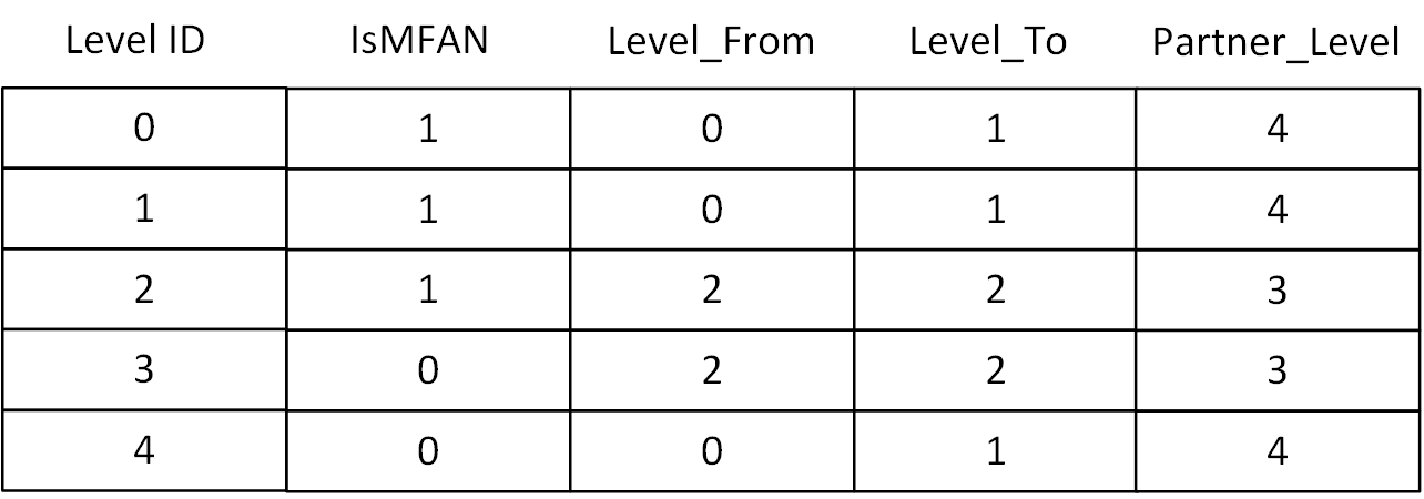
The value varies among groups. It is unacceptable if we store all values on chip, considering the huge number of groups we have. Fortunately, it is not hard to show that the value of for an arbitrary group can be computed by the following information: 1) the level that all partner nodes reside in, denoted as , which is 4 in this example; 2) the MFAN ID, specified by (, ), which refers to the node in level, node in that level; 3) the number of levels sharing the same partner level, denoted as . We propose storing such information in an on-chip lookup table, as shown in Fig. 7. In Fig. 7, column ’IsMFAN’ contains a single bit indicating whether nodes in a level are MFANs in their groups. Column ’PartnerLevel’ denotes the level containing partners nodes, which is . Column ’LevelFrom’ refers to the starting level being paired with , and column ’LevelTo’ is the ending level being paired with . Essentially, variable can be computed by subtracting ’LevelTo’ by ’LevelFrom’ for a given level ID. Then, can be easily computed by
| (3) |
where term is the first node in level ; ChunkID can be computed by value , which is 1 in our example; ChunkSize can be found by the value of by dividing the number of nodes in level by , which is 8 in our example; PartID can be found with the value of , which is 1 in our example; and finally, PartSize can be found by dividing ChunkSize by the number of nodes in level , which is 4 in this example. Plug all values into equation 3, we get .
This deterministic movement pattern implies that we do not need an expensive mapping table for each group, instead we simply can implement the circuitry necessary to calculate the exact locations of each of the nodes in the ORAM controller.
4.2.2 Triggering MFAN Movement
To trigger gap movement, Start-Gap [28] reserves an on-chip counter for each group in the NVM. Each counter stores the number of writes to its corresponding group. When a counter reaches a threshold, , Start-Gap will trigger gap movement on that group. Start-Gap defines as wear-leveling frequency [28]. We will use the same definition here. In our case, we employ a similar mechanism in our design. Ideally, we could store on-chip counters for all groups, but this is unrealistic because of the extremely large number of groups generated by our partition algorithm. Fortunately, we observe strong correlations among the number of writes to groups. Recall that ORAM assumes a random leaf node access. This random number is assumed to be uniformly distributed. Therefore, we can compute the expected number of writes to each node, and therefore, to each group given the static ORAM tree partitions. Then, if we reserve one global counter which stores the total number of ORAM accesses so far, then we could compute the expected number of memory writes to any group. In addition, we found that for a group whose MFAN is located in level , denoted as ( may refer to groups), the expected number of writes to group is around half of . This is true because the MFAN node in receives half number of writes compared to the MFAN node in , and the number of partner nodes in is also half of the number of partner nodes in . If partner nodes in and those in are located in the same level, then the expected number of writes to group is exactly half of .
Since the expected number of writes to a group is determined by its MFAN, then we could simply reserve 1 on-chip counter, , to store the total number of writes to the NVM. For , we perform MFAN movement with a period of , and for , we perform MFAN movement with half frequency compared to , etc. The equivalent expression is that for every ORAM accesses, all will perform MFAN movements; for every ORAM accesses, all and will perform MFAN movements, etc. Therefore, the MFAN movement triggering algorithm can be formulated as shown in algorithm 1:
In algorithm 1, refers to the on-chip counter; refers to the MFAN level. In Fig. 5, the value of will be 2. The return value, , essentially states that MFAN movements need to be performed on , … .
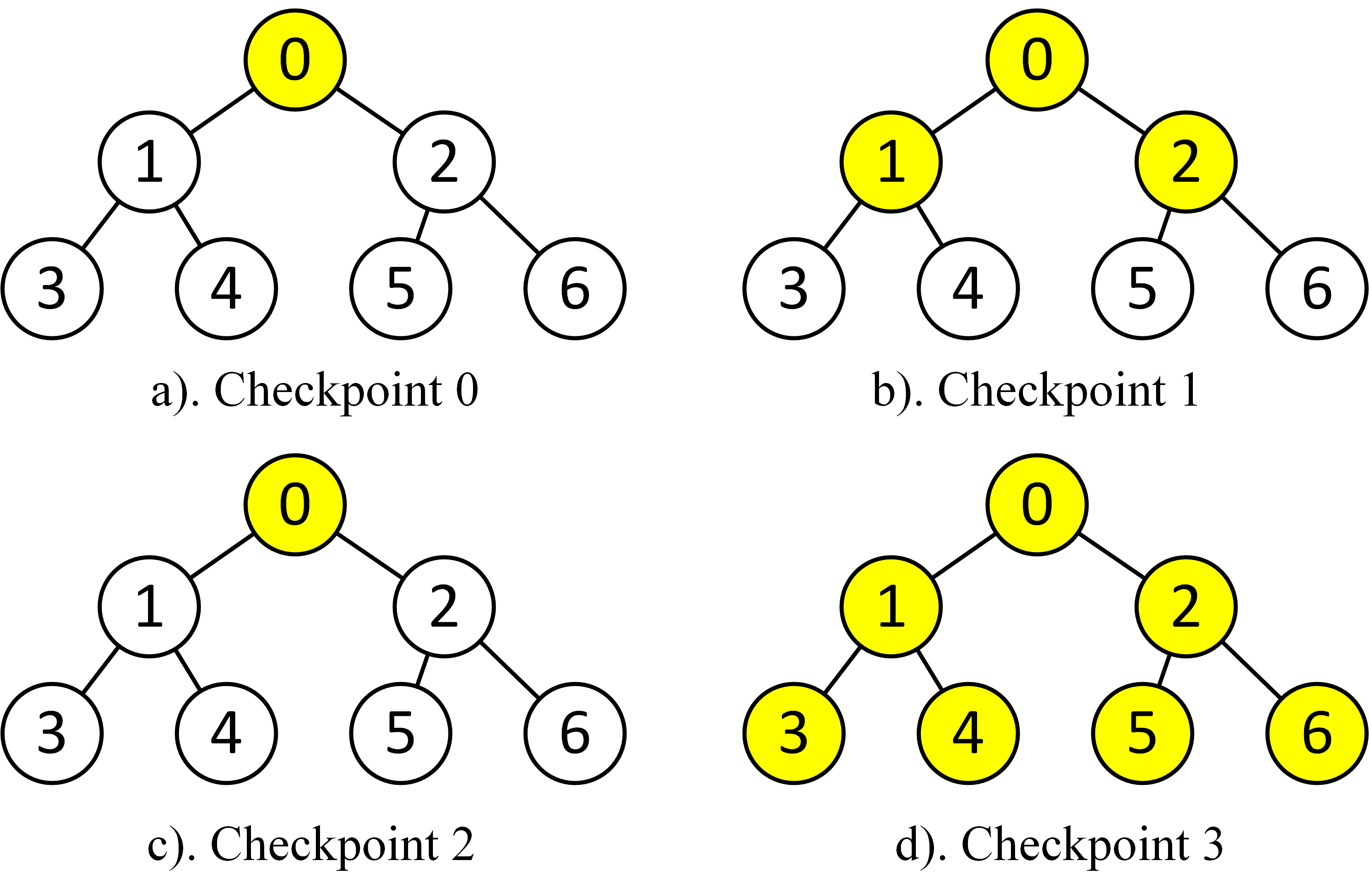
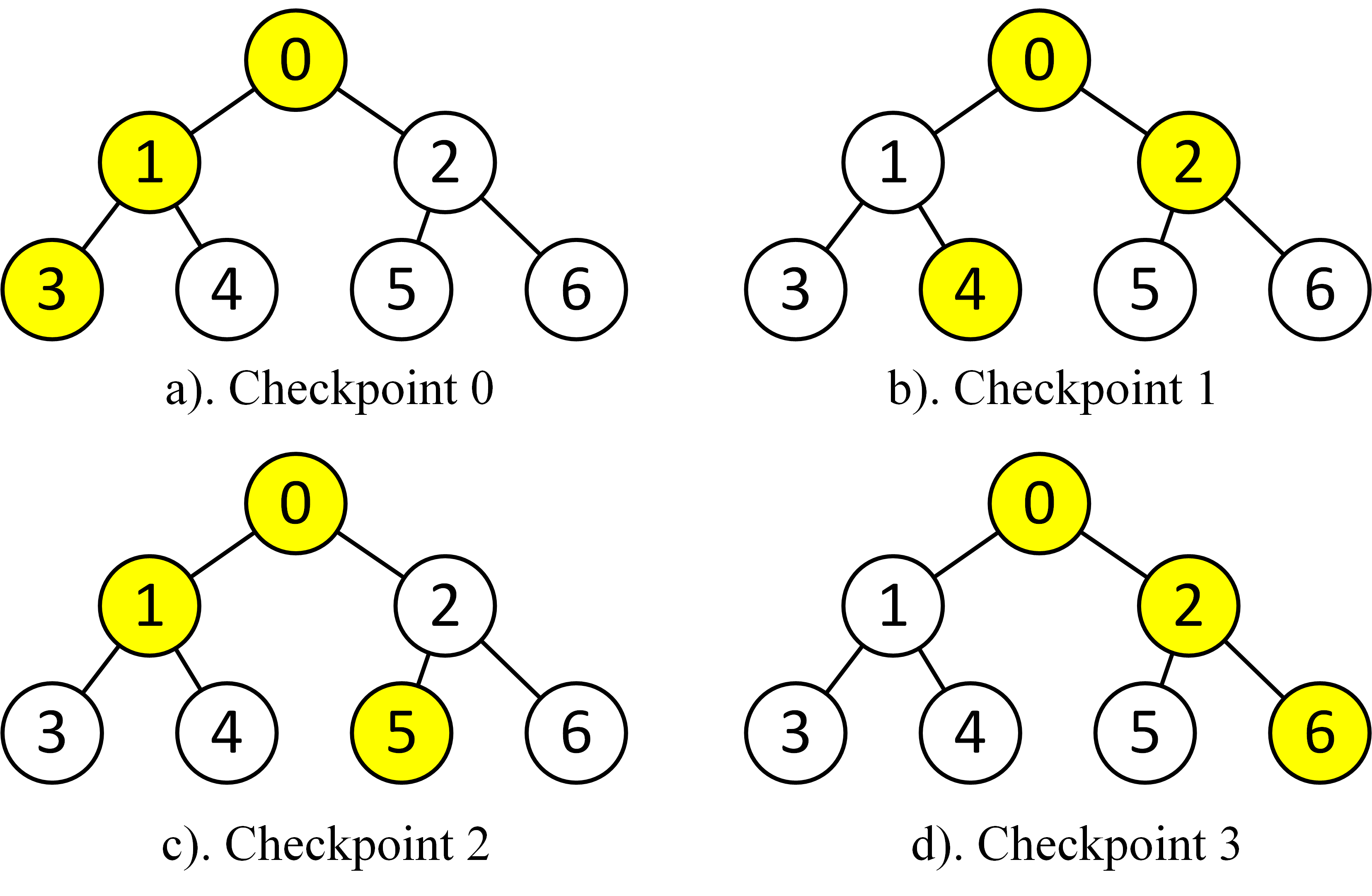
One of the drawbacks of algorithm 1 is that when the counter hits , then all groups need to perform MFAN movements. The large number of MFAN movements performed at the same time could starve out actual ORAM accesses that need to be performed. For example, there are groups for a 32-level ORAM tree. To avoid this concern, we improve our MFAN movement triggering algorithm to stagger the MFAN movements. We shall work through an example to illustrate the problem and our solution. For simplicity, we define a checkpoint as each time satisfies. The first time reaches , we define it as checkpoint 0. Fig. 8 shows such an example. Suppose we have an ORAM tree with MFAN level . Then, at checkpoint 0, only the group whose MFAN node is the root node needs to perform MFAN movement. At checkpoint 1, 3 groups colored in yellow needs to perform MFAN movement. At checkpoint 2, only the root group needs to perform MFAN movement. This is because , so remains 0. At checkpoint 3, since , so is 2 now, we need to perform MFAN movement for all 7 yellow groups. This imbalance of the number of MFAN movements at each checkpoint could cause an ORAM request to be blocked for a long time. Alternatively, we observe that we can solve this problem simply by rearranging the order of doing these MFAN movements, as shown in Fig. 9. We notice that we can perform exactly three MFAN movements at each checkpoint. At checkpoint 0, we perform MFAN movement for the groups whose MFAN node is the first node in each level. At checkpoint 1, we perform MFAN movement for those with MFAN node being the second node in each level. Essentially, the MFAN node ID that we need to perform MFAN movement can be computed by taking checkpoint modulo the number of nodes in each MFAN level. This will give us MFAN (0, 0, 2) for checkpoint 2, which corresponds to nodes (0, 1, 5), respectively; and (0, 1, 3) for checkpoint 3, which corresponds to nodes (0, 2, 6), respectively.
While this looks good enough, we still observe the similar drawback. That is, at each checkpoint, the corresponding ORAM request will suffer more MFAN movements compared with an ordinary ORAM request. We can leverage this by spreading the MFAN movements across the ORAM requests. That is, when each time hits , we will perform exactly one MFAN movement for one group. In this way, one ORAM request will see at most one additional MFAN movement operation.
Finally, we need to choose the appropriate MFAN movement frequency . A small causes too many MFAN movements and increases the overhead of the wear-leveling algorithm due to additional memory accesses incurred while a very large causes too few MFAN movements, hindering efficient wear-leveling. After experimenting with different values of , we observed that for a Wmax of [14], that a frequency of 10000 incurs about 0.1% increase memory accesses while also helping us achieve significant lifetime improvements. The detailed performance impact of will be discussed in 5.1.
5 Algorithm Overhead
In this section, we discuss the performance and storage overheads incurred by E-ORAM.
5.1 Performance Overhead
The performance overhead incurred by E-ORAM can be broken down into two components: (i) overhead due to additional memory reads and writes incurred for MFAN movements and (ii) overhead due to additional logic in the ORAM controller for logical node ID to physical node ID translation, etc.
MFAN movement overhead: Systems with ORAM are usually bottlenecked by memory due to the sheer number of memory accesses that need to be performed for each ORAM access. So, calculating the number of additional memory accesses performed due to E-ORAM gives us a reasonable approximation of the performance overhead incurred.
For each MFAN movement, a total of two node reads and two node writes need to be performed. From our node remapping algorithm in section 4.2, we know that an MFAN movement occurs every ORAM accesses, where is the wear-leveling frequency and is the MFAN level. The total number of node reads (or writes) performed for every ORAM requests (not counting the additional number of reads or writes caused by wear-leveling) is and our algorithm introduces an additional two reads (or writes), bringing the overhead to:
| (4) |
For a 32-level ORAM tree, its MFAN level is , and E-ORAM would cause a 0.0175% increase in the number of reads and writes, a negligible overhead.
ORAM controller overhead: The other performance overhead is from additional operations performed at the ORAM controller, like lookup table reconstruction, logical node ID to physical node ID translation, etc. We did RTL level synthesis of such hardware, which contains combinational logic, and the result shows that the overhead is small and can be parallelized with other ORAM controller actions on the critical path of an ORAM access. Hence this part of the performance overhead is also negligible.
5.2 Storage Overhead
The storage overhead incurred by our algorithm is entirely on-chip for: (i) a counter to track the number of ORAM accesses performed and (ii) a lookup table for storing the static partition information, which is used to compute node remapping in 4.2. For the counter, a 64-bit counter is enough to track ORAM accesses, well over the lifetime of a 32-level ORAM tree even with a Wmax of .
The other storage overhead is the lookup table where each entry contains four elements: one Boolean variable ’MFAN level’, and 3 integers used to store level information. The Boolean variable occupies 1 bit per entry. For the three integers, 6 bits each is enough for trees with up to 64 levels. Hence, the lookup table overhead is
| (5) |
For a 32-level ORAM tree, the lookup table overhead is merely 76 bytes, leading to 84 bytes overhead in total. This concludes that E-ORAM incurs minimal storage overhead.
6 Discussion
Security implications: While our algorithm significantly improves NVM lifetime, it breaks away from ORAM algorithm in that under ORAM, every program memory access needs to be translated into an ORAM access. In E-ORAM, when an MFAN movement is triggered, we do not further translate this into ORAM accesses. We argue that this change does not break ORAM’s obliviousness nor does it add any new security vulnerabilities. This is so, as with this, the attacker now only additionally knows that an MFAN movement is triggered, and ORAM accesses have been executed since last MFAN movement. This does not leak information regarding the application unique behavior apart from the number of ORAM accesses that have been performed, which the attacker is already privy to.
We will now discuss how E-ORAM could be potentially integrated with existing variations of ORAM that aim to improve ORAM performance.
Ring ORAM: Ring ORAM [32] saves ORAM bandwidth by fetching a single block per path read, instead of the entire path, and writing back a deterministic path every path read operations. Every path read operation will incur an update to that block metadata. This significantly saves ORAM bandwidth and extends NVM lifetime (measured in days) by times. However, Ring ORAM still incurs skewed access pattern, and E-ORAM could work well with it. Further optimizations could be made if we incorporate E-ORAM with Ring ORAM, but this is out of the scope of this paper.
DRAM+NVM [29]: Qureshi et al. [29] proposed a DRAM and NVM hybrid memory system. If we apply ORAM on this hybrid memory system, we could 1) cache some blocks on smaller tree on the DRAM (called ), and store all blocks on the NVM, (This architecture is proposed in [25].) or 2) split the address space across both DRAM and NVM, such that the top more frequently written nodes are mapped to DRAM. For the first scenario, the lifetime of the NVM could be extended by receiving less frequently writes, but since the tree size of the NVM does not change, and the access pattern to the NVM does not change, so the lifetime (percentage lifetime) of the NVM does not change. For the second scenario, the DRAM acts as a bigger tree-top cache [24]. If the DRAM size is 3% of NVM size [29], and the ORAM tree in the NVM has 32 levels (NVM tree), then the ORAM tree in the DRAM (DRAM tree) has 27 levels. This extremely large tree-top cache leads to the access pattern to the NVM to be smaller ORAM tree with five levels each. Admittedly, if we apply baseline start-gap on these 5-level ORAM trees, the lifetime could be significantly boosted without E-ORAM. However, we claim that the performance of setup 1) outperforms setup 2). If we define the DRAM access latency as , and define NVM access latency as , then we could compute the average memory access time (AMAT) for both setups:
where refers to the miss rate. It is not hard to show that as long as is less than , will be less than .
Since Setup 1) could give user better performance, and its NVM has a bigger tree, then E-ORAM will certainly outperforms Start-Gap as being measured by lifetime.
| Processor | |
|---|---|
| ISA | UltraSPARC III ISA |
| CMP Size and Core Freq. | 1-core, 2.6 GHz |
| Re-Order-Buffer | 128 entry |
| NVM Parameters | |
| NVM Device Parameters | 2 ranks per channel, |
| 8 banks per chip, | |
| 32768 rows per bank | |
| NVM Bus Frequency | 2666 MHz |
| NVM Write Queue Size | 64 entries |
| NVM Cache Line Endurance | writes |
| ORAM Configuration | |
| Block Size | 64B |
| Bucket Size | 4 cache lines |
| ORAM Tree Level | 24 |
| PLB Size | 64KB |
| Encryption/Decryption Latency | 21 cycles |
| Number of Recursive PosMaps | 4 |
| Stash Size | 200 entries |

7 Evaluation
7.1 Methodology
We evaluate the performance overhead of E-ORAM by applying USIMM, a trace-based cycle accurate memory simulator [6]. We implemented Freecursive ORAM [12] as well as our wear-leveling engine on USIMM. On the backend, we employed an FR-FCFS memory scheduling policy [34]. For the ORAM tree, we simulated a relatively small 24-level tree, due to very long simulation time for larger trees. Table 1 shows the configuration of our simulator and the ORAM tree. For traces, we employed a similar mechanism with [38]. We select 15 workloads from state-of-art benchmarks, 15 from SPEC CPU® 2017[4] 111More information about SPEC CPU® 2017 can be obtained from https://www.spec.org/cpu2017. 222SPEC CPU® is a registered trademark of the Standard Performance Evaluation Corporation.. These workloads are selected for the fact that these workloads are the most memory-intensive workloads [36, 38]. The traces are then collected for 5 million memory reads and writes, after workloads being fast-forwarded to warm up the LLC.
State-of-the-art comparisons: We compare E-ORAM with five ORAM settings/configurations: 1) ORAM algorithm without any wear-leveling algorithm nor any variants of ORAM, which is our baseline; 2) ORAM algorithm accommodated with Start-Gap [28]; 3) ORAM algorithm accommodated with Start-Gap and a 1MB treetop cache [24]; and 4) Fork Path algorithm [42] augmented with Start-Gap and a 1MB merge-aware-cache (MAC). For Start-Gap, we use 256 equal-size groups to maximize lifetime.
7.2 Results
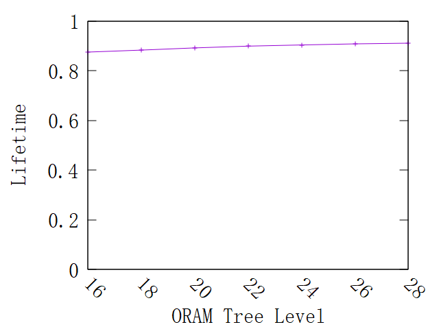
NVM lifetime for varying ORAM tree sizes: Fig. 10 shows the simulated lifetime for different ORAM tree sizes. As shown in Fig. 10, E-ORAM achieves a 87.45% lifetime for a 16-level ORAM tree, and the lifetime gradually increases as we scale the ORAM tree. The lifetime is able to reach 91.04% for a 28-level tree. We are not able to simulate a bigger ORAM tree because of the very long simulation time. We can induce that as the NVM size grows, lifetime continues to grow.
Comparison with the state-of-the-art: Fig. 11 shows the simulation results when comparing E-ORAM with other four comparison designs mentioned in §7.1. We simulate the five configurations with different ORAM tree sizes and collect the number of ORAM accesses being done before device fails. The y-axis is computed by normalizing the total number of ORAM accesses collected from a configuration with the number collected from the baseline configuration. We plot the result in log scale because we observe a huge lifetime gain from E-ORAM. As shown in Fig. 11, the baseline configuration has a number of 1. Start gap performs roughly 4x better compared to the baseline. With the help of 1MB treetop cache, start gap could further improve the number of ORAM accesses to around 8x. If we apply Fork Path on top of start gap, and employ a MAC, due to Fork Path’s nature of merging redundant node accesses, we could further improve the number of ORAM accesses to 9x maximum. Compared to all these configurations, E-ORAM could significantly boost the number of ORAM accesses to 90x. This is even 10x compared to configuration 4), the Fork Path configuration. The reason that E-ORAM works so well is that E-ORAM dynamically adjust the grouping based on the expected number of writes per node. This information is embedded in the nature of ORAM and is not employed by previous wear-leveling algorithms.
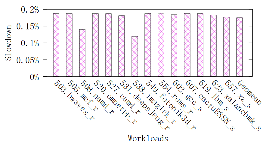
Performance impact: Fig. 12 shows the slowdown caused by E-ORAM for SPEC CPU® 2017 benchmarks. As shown in Fig. 12, E-ORAM incurs negligible performance overhead, ranging from 0.119% (538.imagick_r) to 0.187% (554.roms_r). We observed similar results with GAP benchmarks [3]. We also measured that additional memory accesses generated by E-ORAMare about 0.22%.
8 Related Work
ORAM: Several works [33, 12, 24, 42, 25] build and improve upon Path ORAM [37], considered one of the most state-of-art implementation of ORAM primitive. Our work is orthogonal and complementary to these proposals.
Wear-leveling and write reduction: Prior solutions to tackle NVM endurance either reduce write traffic to NVM (write reduction) or employ wear-levelling to even out write traffic to memory. Our proposed solution E-ORAM is orthogonal to write reduction techniques such as LEO [30] which reduce NVM writes by decreasing block encryptions.
Park et al. [7] proposed an age-based adaptive swapping and shifting wear-leveling algorithm that keeps track of the number of writes. Based on the tracked access pattern, they swap pages and shift lines in a page. However, this design introduces relatively large on-chip storage overhead compared to E-ORAM. Ferreira et al. [11] proposed a wear-leveling algorithm that randomly picks two pages to be swapped. While this design is simple, it fails to achieve uniform write pattern in the case of ORAM, because the most frequently written node (the root node) is unlikely to be picked due to the large number of nodes in the ORAM tree. Hu et al. [18] proposed a software-based wear-levelling algorithm to spread data across PCM uniformly. However, this technique cannot be applied in the presence of ORAM, because the ORAM controller will still create an exponentially distributed memory access pattern. Chang et al. [5] proposed a wear-levelling technique using sliding window with dynamic window size. Memory writes to addresses within the window are tracked. The memory lines are swapped based on the number of observed writes.
9 Conclusions
ORAM incurs an exponentially distributed memory write pattern causing significant lifetime reductions in NVM devices due to their limited write endurance. We present E-ORAM, that leverages this skewed, but deterministic memory access pattern to mitigate NVM lifetime reductions. E-ORAM uses a pre-computed static partition grouping technique to determine wear-leveling granularity and an efficient intra-group wear-leveling algorithm. Finally, we show that E-ORAM introduces less than 0.2% performance overhead, negligible storage overhead (84 bytes for a 32-level ORAM tree), with 90x lifetime boost compared to no wear-leveling.
References
- [1] Intel Optane Persistent Memory and SAP HANA Platform Configuration. Intel and SAP.
- [2] Shaizeen Aga and Satish Narayanasamy. Invisipage: Oblivious demand paging for secure enclaves. In Proceedings of the 46th International Symposium on Computer Architecture, ISCA ’19, page 372–384, New York, NY, USA, 2019. Association for Computing Machinery.
- [3] Scott Beamer, Krste Asanović, and David Patterson. The gap benchmark suite, 2017.
- [4] James Bucek, Klaus-Dieter Lange, and Jóakim v. Kistowski. Spec cpu2017: Next-generation compute benchmark. In Companion of the 2018 ACM/SPEC International Conference on Performance Engineering, ICPE ’18, page 41–42, New York, NY, USA, 2018. Association for Computing Machinery.
- [5] Hung-Sheng Chang, Yuan-Hao Chang, Pi-Cheng Hsiu, Tei-Wei Kuo, and Hsiang-Pang Li. Marching-based wear-leveling for pcm-based storage systems. ACM Trans. Des. Autom. Electron. Syst., 20(2), March 2015.
- [6] Niladrish Chatterjee, Rajeev Balasubramonian, Manjunath Shevgoor, Seth H. Pugsley, Aniruddha N. Udipi, Ali Shafiee, Kshitij Sudan, Manu Awasthi, and Zeshan Chishti. Usimm: the utah simulated memory module a simulation infrastructure for the jwac memory scheduling championship, 2012.
- [7] C. Chen, P. Hsiu, T. Kuo, C. Yang, and C. M. Wang. Age-based pcm wear leveling with nearly zero search cost. In DAC Design Automation Conference 2012, pages 453–458, 2012.
- [8] Victor Costan, Ilia Lebedev, and Srinivas Devadas. Sanctum: Minimal hardware extensions for strong software isolation. In 25th USENIX Security Symposium (USENIX Security 16), pages 857–874, Austin, TX, August 2016. USENIX Association.
- [9] D. Mazieres D. Boneh and R. A. Popa. Remote oblivious storage: Making oblivious ram practical. Manuscript, 2011.
- [10] John Demme, Robert Martin, Adam Waksman, and Simha Sethumadhavan. Side-channel vulnerability factor: A metric for measuring information leakage. In Proceedings of the 39th Annual International Symposium on Computer Architecture, ISCA ’12, page 106–117, USA, 2012. IEEE Computer Society.
- [11] Alexandre P. Ferreira, Miao Zhou, Santiago Bock, Bruce Childers, Rami Melhem, and Daniel Mossé. Increasing pcm main memory lifetime. In Proceedings of the Conference on Design, Automation and Test in Europe, DATE ’10, page 914–919, Leuven, BEL, 2010. European Design and Automation Association.
- [12] Christopher Fletcher, Ling Ren, Albert Kwon, Marten van Dijk, and Srinivas Devadas. Freecursive oram: [nearly] free recursion and integrity verification for position-based oblivious ram. ACM SIGPLAN Notices, 50:103–116, 05 2015.
- [13] R. F. Freitas and W. W. Wilcke. Storage-class memory: The next storage system technology. IBM Journal of Research and Development, 52(4.5):439–447, 2008.
- [14] Vaibhav Gogte, William Wang, Stephan Diestelhorst, Aasheesh Kolli, Peter M. Chen, Satish Narayanasamy, and Thomas F. Wenisch. Software wear management for persistent memories. In Proceedings of the 17th USENIX Conference on File and Storage Technologies, FAST’19, page 45–63, USA, 2019. USENIX Association.
- [15] O. Goldreich. Towards a theory of software protection and simulation by oblivious rams. In Proceedings of the Nineteenth Annual ACM Symposium on Theory of Computing, STOC ’87, page 182–194, New York, NY, USA, 1987. Association for Computing Machinery.
- [16] Michael T. Goodrich and Michael Mitzenmacher. Privacy-preserving access of outsourced data via oblivious ram simulation. In Luca Aceto, Monika Henzinger, and Jiří Sgall, editors, Automata, Languages and Programming, pages 576–587, Berlin, Heidelberg, 2011. Springer Berlin Heidelberg.
- [17] J. Alex Halderman, Seth D. Schoen, Nadia Heninger, William Clarkson, William Paul, Joseph A. Calandrino, Ariel J. Feldman, Jacob Appelbaum, and Edward W. Felten. Lest we remember: Cold-boot attacks on encryption keys. Commun. ACM, 52(5):91–98, May 2009.
- [18] J. Hu, M. Xie, C. Pan, C. J. Xue, Q. Zhuge, and E. H. . Sha. Low overhead software wear leveling for hybrid pcm + dram main memory on embedded systems. IEEE Transactions on Very Large Scale Integration (VLSI) Systems, 23(4):654–663, 2015.
- [19] Paul Kocher, Joshua Jaffe, Benjamin Jun, and Pankaj Rohatgi. Regular paper introduction to differential power analysis. J. Cryptographic Engineering, 1:5–27, 04 2011.
- [20] Emre Kultursay, Mahmut Kandemir, Anand Sivasubramaniam, and Onur Mutlu. Evaluating stt-ram as an energy-efficient main memory alternative. In ISPASS 2013 - IEEE International Symposium on Performance Analysis of Systems and Software, ISPASS 2013 - IEEE International Symposium on Performance Analysis of Systems and Software, pages 256–267, 2013. Copyright: Copyright 2013 Elsevier B.V., All rights reserved.; 2013 IEEE International Symposium on Performance Analysis of Systems and Software, ISPASS 2013 ; Conference date: 21-04-2013 Through 23-04-2013.
- [21] Eyal Kushilevitz, Steve Lu, and Rafail Ostrovsky. On the (In)security of Hash-based Oblivious RAM and a New Balancing Scheme, pages 143–156.
- [22] Benjamin Lee, Engin Ipek, Onur Mutlu, and Doug Burger. Architecting phase change memory as a scalable dram alternative. volume 37, pages 2–13, 06 2009.
- [23] Dayeol Lee, David Kohlbrenner, Shweta Shinde, Krste Asanović, and Dawn Song. Keystone: An open framework for architecting trusted execution environments. In Proceedings of the Fifteenth European Conference on Computer Systems, EuroSys ’20, New York, NY, USA, 2020. Association for Computing Machinery.
- [24] Martin Maas, Eric Love, Emil Stefanov, Mohit Tiwari, Elaine Shi, Krste Asanovic, John Kubiatowicz, and Dawn Song. Phantom: Practical oblivious computation in a secure processor. In Proceedings of the 2013 ACM SIGSAC Conference on Computer & Communications Security, CCS ’13, page 311–324, New York, NY, USA, 2013. Association for Computing Machinery.
- [25] Chandrasekhar Nagarajan, Ali Shafiee, Rajeev Balasubramonian, and Mohit Tiwari. : Relaxed hierarchical oram. In Proceedings of the Twenty-Fourth International Conference on Architectural Support for Programming Languages and Operating Systems, ASPLOS ’19, page 659–671, New York, NY, USA, 2019. Association for Computing Machinery.
- [26] Olga Ohrimenko, Manuel Costa, Cédric Fournet, Christos Gkantsidis, Markulf Kohlweiss, and Divya Sharma. Observing and preventing leakage in mapreduce. In Proceedings of the 22nd ACM SIGSAC Conference on Computer and Communications Security, CCS ’15, page 1570–1581, New York, NY, USA, 2015. Association for Computing Machinery.
- [27] Jean-Jacques Quisquater and David Samyde. Side channel cryptanalysis. In Workshop on the Security of Communications on the Internet (SECI)., 2002.
- [28] Moinuddin K. Qureshi, John Karidis, Michele Franceschini, Vijayalakshmi Srinivasan, Luis Lastras, and Bulent Abali. Enhancing lifetime and security of pcm-based main memory with start-gap wear leveling. In Proceedings of the 42nd Annual IEEE/ACM International Symposium on Microarchitecture, MICRO 42, page 14–23, New York, NY, USA, 2009. Association for Computing Machinery.
- [29] Moinuddin K. Qureshi, Vijayalakshmi Srinivasan, and Jude A. Rivers. Scalable high performance main memory system using phase-change memory technology. In Proceedings of the 36th Annual International Symposium on Computer Architecture, ISCA ’09, page 24–33, New York, NY, USA, 2009. Association for Computing Machinery.
- [30] Joydeep Rakshit and Kartik Mohanram. Leo: Low overhead encryption oram for non-volatile memories. IEEE Computer Architecture Letters, PP:1–1, 01 2018.
- [31] S. Raoux, G. W. Burr, M. J. Breitwisch, C. T. Rettner, Y. . Chen, R. M. Shelby, M. Salinga, D. Krebs, S. . Chen, H. . Lung, and C. H. Lam. Phase-change random access memory: A scalable technology. IBM Journal of Research and Development, 52(4.5):465–479, 2008.
- [32] Ling Ren, Christopher Fletcher, Albert Kwon, Emil Stefanov, Elaine Shi, Marten van Dijk, and Srinivas Devadas. Constants count: Practical improvements to oblivious RAM. In 24th USENIX Security Symposium (USENIX Security 15), pages 415–430, Washington, D.C., August 2015. USENIX Association.
- [33] Ling Ren, Xiangyao Yu, Christopher W. Fletcher, Marten van Dijk, and Srinivas Devadas. Design space exploration and optimization of path oblivious ram in secure processors. In Proceedings of the 40th Annual International Symposium on Computer Architecture, ISCA ’13, page 571–582, New York, NY, USA, 2013. Association for Computing Machinery.
- [34] Scott Rixner, William J. Dally, Ujval J. Kapasi, Peter Mattson, and John D. Owens. Memory access scheduling. In Proceedings of the 27th Annual International Symposium on Computer Architecture, ISCA ’00, page 128–138, New York, NY, USA, 2000. Association for Computing Machinery.
- [35] Felix Schuster, Manuel Costa, Cédric Fournet, Christos Gkantsidis, Marcus Peinado, Gloria Mainar-Ruiz, and Mark Russinovich. Vc3: Trustworthy data analytics in the cloud. Technical Report MSR-TR-2014-39, February 2014.
- [36] Sarabjeet Singh and Manu Awasthi. Memory centric characterization and analysis of spec cpu2017 suite. In Proceedings of the 2019 ACM/SPEC International Conference on Performance Engineering, ICPE ’19, page 285–292, New York, NY, USA, 2019. Association for Computing Machinery.
- [37] Emil Stefanov, Marten van Dijk, Elaine Shi, Christopher Fletcher, Ling Ren, Xiangyao Yu, and Srinivas Devadas. Path oram: An extremely simple oblivious ram protocol. In Proceedings of the 2013 ACM SIGSAC Conference on Computer & Communications Security, CCS ’13, page 299–310, New York, NY, USA, 2013. Association for Computing Machinery.
- [38] Meysam Taassori, Rajeev Balasubramonian, Siddhartha Chhabra, Alaa R. Alameldeen, Manjula Peddireddy, Rajat Agarwal, and Ryan Stutsman. Compact leakage-free support for integrity and reliability. In Proceedings of the ACM/IEEE 47th Annual International Symposium on Computer Architecture, ISCA ’20, page 735–748. IEEE Press, 2020.
- [39] C. Xu, D. Niu, N. Muralimanohar, R. Balasubramonian, T. Zhang, S. Yu, and Y. Xie. Overcoming the challenges of crossbar resistive memory architectures. In 2015 IEEE 21st International Symposium on High Performance Computer Architecture (HPCA), pages 476–488, 2015.
- [40] Y. Xu, W. Cui, and M. Peinado. Controlled-channel attacks: Deterministic side channels for untrusted operating systems. In 2015 IEEE Symposium on Security and Privacy, pages 640–656, 2015.
- [41] Danfeng Zhang, Aslan Askarov, and Andrew C. Myers. Predictive mitigation of timing channels in interactive systems. In Proceedings of the 18th ACM Conference on Computer and Communications Security, CCS ’11, page 563–574, New York, NY, USA, 2011. Association for Computing Machinery.
- [42] Xian Zhang, Guangyu Sun, Chao Zhang, Weiqi Zhang, Yun Liang, Tao Wang, Yiran Chen, and Jia Di. Fork path: Improving efficiency of oram by removing redundant memory accesses. In Proceedings of the 48th International Symposium on Microarchitecture, MICRO-48, page 102–114, New York, NY, USA, 2015. Association for Computing Machinery.
- [43] Y. Zhang and S. Swanson. A study of application performance with non-volatile main memory. In 2015 31st Symposium on Mass Storage Systems and Technologies (MSST), pages 1–10, May 2015.