AI-based Agents for Automated Robotic Endovascular Guidewire Manipulation
INTRODUCTION
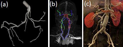
Endovascular guidewire manipulation is essential for minimally-invasive clinical applications; Percutaneous Coronary Intervention (PCI) is used to open narrowed coronary arteries and restore arterial blood flow to heart tissue, Mechanical thrombectomy techniques for acute ischemic stroke (AIS) to remove blood clots from the brain veins, and Transjugular intrahepatic portosystemic shunt (TIPS) for liver portal hypertension use a special needle and position a wire between the portal vein through the liver. All procedures commonly require 3D vessel geometries from 3D CTA (Computed Tomography Angiography) images (Fig. 1). During these procedures, the clinician generally places a guiding catheter in the ostium of the relevant vessel and then manipulates a wire through the catheter and across the blockage. The clinician only uses X-ray fluoroscopy intermittently to visualize and guide the catheter, guidewire, and other devices (e.g., angioplasty balloons and stents).
Various types of endovascular robot-assisted systems [2, 3] are being developed to provide efficient positional control of devices, helping clinicians to mitigate therapeutical risks. The primary motions that a clinician can use to control the movement and direction of the wire are rotation and pushing/retracting from the proximal end of the wire outside the insertion point on the patient’s body.
Even with these robotic devices, clinicians passively control guidewires/catheters by relying on limited indirect observation (i.e., 2D partial view of devices, and intermittent updates due to radiation limit) from X-ray fluoroscopy. Modeling and controlling the guidewire manipulation in coronary vessels remains challenging because of the complicated interaction between guidewire motions with different physical properties (i.e., loads, coating) and vessel geometries with lumen conditions resulting in a highly non-linear system. Thus the recent literature has focused on behavior-based automated motion controls; Madder et al. [4] proposed the first known automatic guidewire retraction motions with a rotation of to cannulate a coronary artery bifurcation; In addition, robotic crossing techniques have demonstrated to generate distal guidewire motions that take advantage of the fast response of the robot system, and it’s autonomous and collaborative controls [5, 6].
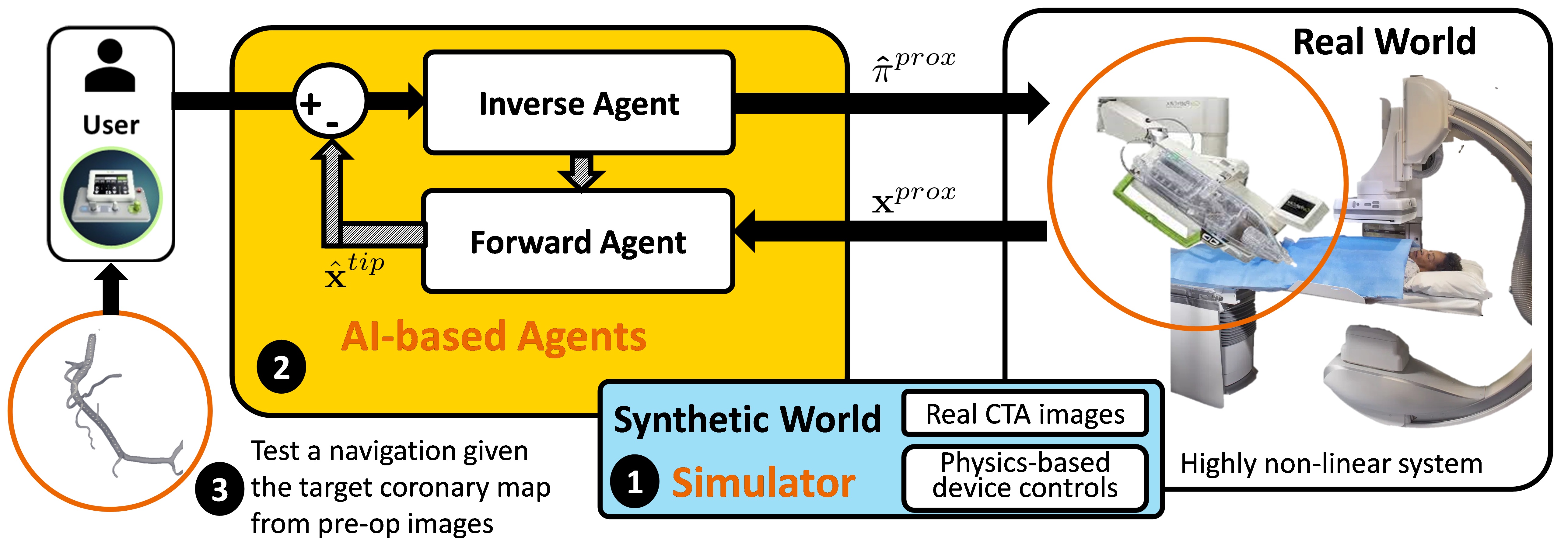
This paper introduces a scalable learning pipeline to train AI-based agent models toward automated endovascular predictive device controls. Figure 2 shows an overview of an endovascular predictive control workflow. Specifically, we create a scalable environment by pre-processing 3D CTA images, providing patient-specific 3D vessel geometry and the centerline of the coronary. Next, we apply a large quantity of randomly generated motion sequences from the proximal end to generate wire states associated with each environment using a physics-based device simulator. Then, we reformulate the control problem to a sequence-to-sequence learning problem, in which we use a Transformer-based model, trained to handle non-linear sequential forward/inverse transition functions.
MATERIALS AND METHODS
At the torquer’s attachment point to the robot, the wire’s proximal state, , has a translation and rotation . At the distal (tip) of the wire, the state is defined by its position and orientation in . The physical parameters of the wire are defined as , including diameter, Poisson ratio, Young modulus, number of elements, etc. Let represent the spatial environment of the vessel, including 3D vessel geometry, 3D vessel centerline, and sectional labels.
Since we do not have a direct measurement for the tip of the guidewire, we simplify with regard to the 3D vessel centerline by projecting it into known 3D vessel centerline. Then, where and represent the translation along the centerline and the distance from the centerline to the tip, respectively.
Then our manipulation system can be treated as a forward/inverse transition function and with control to transition from one state to another state given physical parameters and the spatial environment of vessel :
| (1) | |||
| (2) |
Given and , manipulate the wire to the desired tip state , making all state transitions via and finding the sequence of proximal controls that minimizes estimation cost . Then, the problem follows:
| (3) |
where is the current time and is the long-term time step.
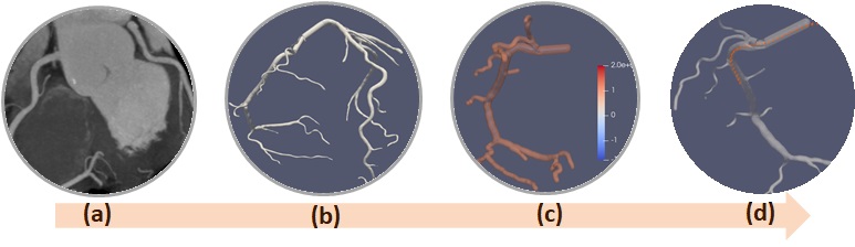
Creating a scalable environment is an important step in getting a better quality of learning-based controls for intelligent agents. Physics-based simulators are commonly used nowadays in various practical fields (e.g., self-driving cars, pick-and-place) to improve the qualities of controls. Similarly, we create the pre-processing pipeline with 3D CTA images and 3D device simulation to create a scalable environment. Figure 3 shows the overall pre-processing pipeline for scalable data. First, given 3D CTA images (Fig. 3(a)), the corresponding 3D segmentation of the whole coronary vessels is computed (Fig. 3(b)). Then, the 3D level set distance map that contains the minimum distance to the vessels at each 3D point is computed to define the boundary conditions (Fig. 3(c)). Finally, we apply the desired force to the proximal section of the wire using the Cosserat-rod model in the simulator, which interacts with the defined boundary conditions by solving partial differential equations. Finally, this provides the scalable simulated device states inside the vessel (Fig. 3(d)).
We solve the control problem by using attention-mechanism-based learning model, Transformer [7]. We use created data from the pre-processing pipeline to train the Transformer model. Our system inherently requires an open loop where spatial feedback of devices is not continuously available due to the radiation limit of X-rays. We train and as dual Transformer models to iteratively update each history of states over time. The input/output are described in Eq (1)(2). Then, we can finally estimate a long sequence of state information (i.e., and , ).
We used 100 CTA images for the right coronary artery as a simulator environment, and applied 1000 randomly generated continuous sequential controls of for 60 seconds, which generated 120 sequence sample points for each set. We used data as the training set and used for the testing set. We then present the safety ratio and difference between the estimated force and the ground-truth in the test set.
Both forward/inverse transformer models are learned with 30 sequences of states as inputs, 1 output (Many-to-one), 12 heads, 4 encoder/decoder layers, 128 dimensions of feedforward, and 0.1 dropouts. The learning rate was set to be for 20 epochs with Adam optimizer in Pytorch.
RESULTS
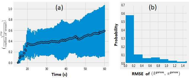
We assumed the first 30 states of are given as measurements. Then, we update states using and iteratively over time. Figure 4 (a) shows a ratio of for the test set, where means the tip is located in the centerline while approaching to 1 represents the tip is close to the vessel wall, which means we might need to obtain new measurements from X-ray in time. The radius of the vessel that we tested is between and . Figure 4 (b) shows the distribution of our control output errors by computing errors between the ground-truth of and our estimation .
DISCUSSION
Based on our results, our AI-based agents might provide an efficient approach to indicate when to turn on/off X-ray. As a future work, we plan to investigate more sophisticated controls for complicated scenarios with a systematic evaluation. In addition, we plan to apply various parameters to handle uncertainty.
DISCLAIMER
The concepts and information presented in this paper are based on research results that are not commercially available. Future availability cannot be guaranteed.
References
- Goren et al. [2018] N. Goren, J. Avery, T. Dowrick, E. Mackle, A. Witkowska-Wrobel, D. Werring, and D. Holder, “Multi-frequency electrical impedance tomography and neuroimaging data in stroke patients,” Scientific Data, vol. 5, p. 180112, 07 2018.
- Rafii-Tari et al. [2013] H. Rafii-Tari, C. Payne, and G.-Z. Yang, “Current and emerging robot-assisted endovascular catheterization technologies: A review,” Annals of biomedical engineering, vol. 42, 11 2013.
- Duan et al. [2023] W. Duan, T. Akinyemi, W. Du, J. Ma, X. Chen, F. Wang, O. Omisore, J. Luo, H. Wang, and L. Wang, “Technical and clinical progress on robot-assisted endovascular interventions: A review,” Micromachines, vol. 14, no. 1, p. 197, Jan 2023.
- Madder et al. [2017] R. Madder, W. Lombardi, M. Parikh, D. Kandzari, J. Grantham, and S. Rao, “Impact of a Novel Advanced Robotic Wiring Algorithm on Time to Wire a Coronary Artery Bifurcation in a Porcine Model,” Journal of the American College of Cardiology, vol. 70, no. 80, 2017.
- Kim et al. [2018a] Y.-H. Kim, A. Kapoor, R. Finocchi, and E. Girard, “Evaluation of High-Speed Dynamic Motions for Robotic Guidewire Crossing Techniques,” in Hamlyn Symposium on Medical Robotics, London, UK, Jun. 2018.
- Kim et al. [2018b] ——, “An experimental validation of behavior-based motions for robotic coronary guidewire crossing techniques,” in Proceedings of the International Symposium on Experimental Robotics, Buenos Aires, Argentina, 2018, pp. 14–23.
- Vaswani et al. [2017] A. Vaswani, N. Shazeer, N. Parmar, J. Uszkoreit, L. Jones, A. N. Gomez, L. u. Kaiser, and I. Polosukhin, “Attention is all you need,” in Advances in Neural Information Processing Systems, vol. 30, 2017.