- 2G
- Second Generation
- 3G
- 3 Generation
- 3GPP
- 3 Generation Partnership Project
- 4G
- 4th Generation
- 5G
- 5th Generation
- 6G
- 6th Generation
- AA
- Antenna Array
- AC
- Admission Control
- ACL
- adjacent channel leakage
- AD
- Attack-Decay
- ADC
- analog-to-digital converter
- ADSL
- Asymmetric Digital Subscriber Line
- AHW
- Alternate Hop-and-Wait
- AMC
- Adaptive Modulation and Coding
- AP
- Access Point
- APA
- Adaptive Power Allocation
- AR
- autoregressive
- ARMA
- Autoregressive Moving Average
- ATES
- Adaptive Throughput-based Efficiency-Satisfaction Trade-Off
- AWGN
- additive white Gaussian noise
- BB
- branch and bound
- BD
- block diagonalization
- BER
- bit error rate
- BF
- Best Fit
- BLER
- BLock Error Rate
- BPC
- Binary power control
- BPSK
- binary phase-shift keying
- BPA
- Best pilot-to-data power ratio (PDPR) Algorithm
- BRA
- Balanced Random Allocation
- BS
- base station
- CAP
- Combinatorial Allocation Problem
- CAPEX
- Capital Expenditure
- CBF
- Coordinated Beamforming
- CBR
- Constant Bit Rate
- CBS
- Class Based Scheduling
- CC
- Congestion Control
- CDF
- Cumulative Distribution Function
- CDMA
- Code-Division Multiple Access
- CL
- Closed Loop
- CLI
- cross-link interference
- CLPC
- Closed Loop Power Control
- CNR
- Channel-to-Noise Ratio
- CPA
- Cellular Protection Algorithm
- CPICH
- Common Pilot Channel
- CoMP
- Coordinated Multi-Point
- CQI
- Channel Quality Indicator
- CRM
- Constrained Rate Maximization
- CRN
- Cognitive Radio Network
- CS
- Coordinated Scheduling
- CSI
- channel state information
- CSIR
- channel state information at the receiver
- CSIT
- channel state information at the transmitter
- CUE
- cellular user equipment
- DAC
- digital-to-analog converter
- D2D
- device-to-device
- DCA
- Dynamic Channel Allocation
- DE
- Differential Evolution
- DFT
- Discrete Fourier Transform
- DIST
- Distance
- DL
- downlink
- DMA
- Double Moving Average
- DMRS
- Demodulation Reference Signal
- D2DM
- D2D Mode
- DMS
- D2D Mode Selection
- DNN
- Deep Neural Network
- DoA
- direction-of-arrival
- DOCSIS
- Data Over Cable Service Interface Specification
- DPC
- Dirty Paper Coding
- DRA
- Dynamic Resource Assignment
- DSA
- Dynamic Spectrum Access
- DSM
- Delay-based Satisfaction Maximization
- EBD
- electrical balance duplexer
- ECC
- Electronic Communications Committee
- EFLC
- Error Feedback Based Load Control
- EI
- Efficiency Indicator
- eNB
- Evolved Node B
- EPA
- Equal Power Allocation
- EPC
- Evolved Packet Core
- EPS
- Evolved Packet System
- E-UTRAN
- Evolved Universal Terrestrial Radio Access Network
- ES
- Exhaustive Search
- FD
- full-duplex
- FDD
- frequency division duplexing
- FDM
- Frequency Division Multiplexing
- FER
- Frame Erasure Rate
- FF
- Fast Fading
- FSB
- Fixed Switched Beamforming
- FST
- Fixed SNR Target
- FTP
- File Transfer Protocol
- GA
- Genetic Algorithm
- GBR
- Guaranteed Bit Rate
- GLR
- Gain to Leakage Ratio
- GOS
- Generated Orthogonal Sequence
- GPL
- GNU General Public License
- GRP
- Grouping
- HARQ
- Hybrid Automatic Repeat Request
- HD
- half-duplex
- HMS
- Harmonic Mode Selection
- HOL
- Head Of Line
- HSDPA
- High-Speed Downlink Packet Access
- HSPA
- High Speed Packet Access
- HTTP
- HyperText Transfer Protocol
- ICMP
- Internet Control Message Protocol
- ICI
- Intercell Interference
- ID
- Identification
- IETF
- Internet Engineering Task Force
- ILP
- Integer Linear Program
- JRAPAP
- Joint RB Assignment and Power Allocation Problem
- MEC
- Multi-Access edge computing
- UID
- Unique Identification
- IAB
- integrated access and backhaul
- IBFD
- in-band full-duplex
- IID
- Independent and Identically Distributed
- IIR
- Infinite Impulse Response
- ILP
- Integer Linear Problem
- IMT
- International Mobile Telecommunications
- INV
- Inverted Norm-based Grouping
- IoT
- Internet of Things
- IP
- Internet Protocol
- IPv6
- Internet Protocol Version 6
- I/Q
- in-phase/quadrature
- IRS
- Intelligent Reflective Surface
- ISAC
- integrated sensing and communications
- ISD
- Inter-Site Distance
- ISI
- Inter Symbol Interference
- ITU
- International Telecommunication Union
- JCAS
- joint communications and sensing
- JOAS
- Joint Opportunistic Assignment and Scheduling
- JOS
- Joint Opportunistic Scheduling
- JP
- Joint Processing
- JS
- Jump-Stay
- KF
- Kalman filter
- KKT
- Karush-Kuhn-Tucker
- L3
- Layer-3
- LAC
- Link Admission Control
- LA
- Link Adaptation
- LC
- Load Control
- LNA
- low-noise amplifier
- LOS
- Line of Sight
- LP
- Linear Programming
- LS
- least squares
- LTE
- Long Term Evolution
- LTE-A
- LTE-Advanced
- LTE-Advanced
- Long Term Evolution Advanced
- M2M
- Machine-to-Machine
- MAC
- Medium Access Control
- MANET
- Mobile Ad hoc Network
- MC
- Modular Clock
- MCS
- Modulation and Coding Scheme
- MDB
- Measured Delay Based
- MDI
- Minimum D2D Interference
- MF
- Matched Filter
- MG
- Maximum Gain
- MH
- Multi-Hop
- MIMO
- multiple-input multiple-output
- MINLP
- Mixed Integer Nonlinear Programming
- MIP
- Mixed Integer Programming
- MISO
- Multiple Input Single Output
- ML
- maximum likelihood
- MLWDF
- Modified Largest Weighted Delay First
- mmWave
- millimeter wave
- MME
- Mobility Management Entity
- MMSE
- minimum mean squared error
- MOS
- Mean Opinion Score
- MPF
- Multicarrier Proportional Fair
- MRA
- Maximum Rate Allocation
- MR
- Maximum Rate
- MRC
- maximum ratio combining
- MRT
- Maximum Ratio Transmission
- MRUS
- Maximum Rate with User Satisfaction
- MS
- mobile station
- MSE
- mean squared error
- MSI
- Multi-Stream Interference
- MTC
- Machine-Type Communication
- MTSI
- Multimedia Telephony Services over IMS
- MTSM
- Modified Throughput-based Satisfaction Maximization
- MU-MIMO
- multiuser multiple input multiple output
- MU
- multi-user
- NAS
- Non-Access Stratum
- NB
- Node B
- NE
- Nash equilibrium
- NCL
- Neighbor Cell List
- NLP
- Nonlinear Programming
- NLOS
- Non-Line of Sight
- NMSE
- Normalized Mean Square Error
- NORM
- Normalized Projection-based Grouping
- NP
- Non-Polynomial Time
- NR
- New Radio
- NRT
- Non-Real Time
- NSPS
- National Security and Public Safety Services
- NTNs
- non-terrestrial networks
- O2I
- Outdoor to Indoor
- OFDMA
- orthogonal frequency division multiple access
- OFDM
- orthogonal frequency division multiplexing
- OFPC
- Open Loop with Fractional Path Loss Compensation
- O2I
- Outdoor-to-Indoor
- OL
- Open Loop
- OLPC
- Open-Loop Power Control
- OL-PC
- Open-Loop Power Control
- OPEX
- Operational Expenditure
- ORB
- Orthogonal Random Beamforming
- JO-PF
- Joint Opportunistic Proportional Fair
- OSI
- Open Systems Interconnection
- PA
- power amplifier
- PAIR
- D2D Pair Gain-based Grouping
- PAPR
- Peak-to-Average Power Ratio
- PBCH
- physical broadcast channel
- P2P
- Peer-to-Peer
- PC
- Power Control
- PCI
- Physical Cell ID
- Probability Density Function
- PDPR
- pilot-to-data power ratio
- PER
- Packet Error Rate
- PF
- Proportional Fair
- P-GW
- Packet Data Network Gateway
- PL
- Pathloss
- PMN
- Perceptive Mobile Network
- PPR
- pilot power ratio
- PRB
- physical resource block
- PROJ
- Projection-based Grouping
- ProSe
- Proximity Services
- PS
- Packet Scheduling
- PSAM
- pilot symbol assisted modulation
- PSO
- Particle Swarm Optimization
- PZF
- Projected Zero-Forcing
- QAM
- Quadrature Amplitude Modulation
- QoS
- Quality of Service
- QPSK
- Quadri-Phase Shift Keying
- RAISES
- Reallocation-based Assignment for Improved Spectral Efficiency and Satisfaction
- RAN
- Radio Access Network
- RA
- Resource Allocation
- RAT
- Radio Access Technology
- RATE
- Rate-based
- RB
- resource block
- RBG
- Resource Block Group
- REF
- Reference Grouping
- RF
- radio frequency
- RIS
- reconfigurable intelligent surface
- RLC
- Radio Link Control
- RM
- Rate Maximization
- RNC
- Radio Network Controller
- RND
- Random Grouping
- RRA
- Radio Resource Allocation
- RRM
- Radio Resource Management
- RSCP
- Received Signal Code Power
- RSRP
- Reference Signal Receive Power
- RSRQ
- Reference Signal Receive Quality
- RR
- Round Robin
- RRC
- Radio Resource Control
- RSSI
- Received Signal Strength Indicator
- RT
- Real Time
- RU
- Resource Unit
- RUNE
- RUdimentary Network Emulator
- RV
- Random Variable
- RX
- receiver
- SAC
- Session Admission Control
- SBFD
- sub-band full-duplex
- SCM
- Spatial Channel Model
- SC-FDMA
- Single Carrier - Frequency Division Multiple Access
- SD
- Soft Dropping
- S-D
- Source-Destination
- SDPC
- Soft Dropping Power Control
- SDMA
- Space-Division Multiple Access
- SER
- Symbol Error Rate
- SES
- Simple Exponential Smoothing
- S-GW
- Serving Gateway
- SI
- self-interference
- SINR
- signal-to-interference-plus-noise ratio
- SIC
- self-interference cancellation
- SIP
- Session Initiation Protocol
- SISO
- single-input single-output
- SIMO
- Single Input Multiple Output
- SIR
- signal-to-interference ratio
- SLNR
- Signal-to-Leakage-plus-Noise Ratio
- SMA
- Simple Moving Average
- SNR
- signal-to-noise ratio
- SORA
- Satisfaction Oriented Resource Allocation
- SORA-NRT
- Satisfaction-Oriented Resource Allocation for Non-Real Time Services
- SORA-RT
- Satisfaction-Oriented Resource Allocation for Real Time Services
- SPF
- Single-Carrier Proportional Fair
- SRA
- Sequential Removal Algorithm
- SRS
- Sounding Reference Signal
- STAR
- simultaneous transmit-and-receive
- SU-MIMO
- single-user multiple input multiple output
- SU
- Single-User
- SVD
- Singular Value Decomposition
- TCP
- Transmission Control Protocol
- TDD
- time division duplexing
- TDMA
- Time Division Multiple Access
- TETRA
- Terrestrial Trunked Radio
- TP
- Transmit Power
- TPC
- Transmit Power Control
- TTI
- Transmission Time Interval
- TTR
- Time-To-Rendezvous
- TSM
- Throughput-based Satisfaction Maximization
- TU
- Typical Urban
- TX
- transmitter
- UE
- user equipment
- UEPS
- Urgency and Efficiency-based Packet Scheduling
- UL
- uplink
- UMTS
- Universal Mobile Telecommunications System
- URI
- Uniform Resource Identifier
- URM
- Unconstrained Rate Maximization
- UT
- user terminal
- VR
- Virtual Resource
- VoIP
- Voice over IP
- WAN
- Wireless Access Network
- WCDMA
- Wideband Code Division Multiple Access
- WF
- Water-filling
- WiMAX
- Worldwide Interoperability for Microwave Access
- WINNER
- Wireless World Initiative New Radio
- WLAN
- Wireless Local Area Network
- WMPF
- Weighted Multicarrier Proportional Fair
- WPF
- Weighted Proportional Fair
- WSN
- Wireless Sensor Network
- WWW
- World Wide Web
- XIXO
- (Single or Multiple) Input (Single or Multiple) Output
- XDD
- cross-division duplex
- ZF
- zero-forcing
- ZMCSCG
- Zero Mean Circularly Symmetric Complex Gaussian
Full-Duplex Wireless for 6G:
Progress Brings New Opportunities and Challenges
Abstract
The use of in-band full-duplex (FD) enables nodes to simultaneously transmit and receive on the same frequency band, which challenges the traditional assumption in wireless network design. The full-duplex capability enhances spectral efficiency and decreases latency, which are two key drivers pushing the performance expectations of next-generation mobile networks. In less than ten years, in-band FD has advanced from being demonstrated in research labs to being implemented in standards, presenting new opportunities to utilize its foundational concepts. Some of the most significant opportunities include using FD to enable wireless networks to sense the physical environment, integrate sensing and communication applications, develop integrated access and backhaul solutions, and work with smart signal propagation environments powered by reconfigurable intelligent surfaces. However, these new opportunities also come with new challenges for large-scale commercial deployment of FD technology, such as managing self-interference, combating cross-link interference in multi-cell networks, and coexistence of dynamic time division duplex, subband FD and FD networks.
Index Terms:
Cross-link interference, full-duplex, self-interference cancellation, localization, integrated access and backhaul, integrated sensing and communication, multiple-input multiple-output systems, reconfigurable intelligent surface, and non-terrestrial networks.I Introduction
The Mobile Internet is a crucial worldwide infrastructure that supports countless services and has exhibited a remarkable growth trajectory that continues to surpass expectations. Over the last five years, wireless broadband subscriptions have experienced an annual increase of 7%, with the total number recently surpassing billion [1]. In the period between the third quarters of and , mobile network data traffic grew by 38%, reaching a usage rate of Exabytes (i.e., 1018 bytes) per month. To meet the future growth of diverse applications, next-generation broadband networks must be ever-more spectrally efficient, and achieve lower latency while reducing infrastructure costs and energy consumption per bit [2, 3]. For wireless innovators, these expectations necessitate questioning current network design principles and encouraging the introduction of disruptive technological solutions [4, 5, 6, 7].
A fundamental assumption in traditional wireless network design has been the half-duplex (HD) communication, according to which a node either transmits or receives a signal in a single channel usage. The HD design assumption manifests itself in the design of all current networks, with frequency division duplexing (FDD) and time division duplexing (TDD) being the two most commonly used techniques. While conceptually simple, in-band full-duplex (FD), which enables simultaneous transmissions and receptions in the same frequency band, was considered practically infeasible till its initial experimental results back in using off-the-shelf radios [8, 9]. Those pioneering proof-of-concepts demonstrated that self-interference (SI) can be sufficiently mitigated, paving the way for practical implementations of the technology. In fact, FD communications were independently discovered and experimentally confirmed by many research groups worldwide [10, 11, 12, 13, 14, 15, 16, 17, 18], ushering a new theoretical and practical research avenue for the wireless communications community [19, 20, 21, 22, 23, 24, 25, 26, 27, 28, 29, 30]. This simultaneous transmit-and-receive (STAR) technology has the potential to increase the spectral efficiency and reduce the latency of wireless systems, which constitute two of the key performance drivers for the design of next generation broadband networking. To this end, the FD technology can enable the convergence of future networks towards a unified communication, sensing, and backhaul platform.
Between 2010 and 2020, there was a significant research and development dedicated to in-band FD wireless communication [31, 32, 33]. In fact, by 2015, the cable modem industry had already adopted in-band full-duplex to create the Data Over Cable Service Interface Specification (DOCSIS) 4.0 standard, which enabled next-generation cable modems to operate in FD mode [34]. By 2020, FD wireless products had begun to appear. Thus, within the span of just one decade, the concept of in-band FD communication has moved from being a laboratory idea to being incorporated into telecommunications standards.
The evolution of envisioned applications and use cases is a defining characteristic of successful technological ideas, which drives technical progress. The same trend is observed in the development of in-band FD technology, which is the central focus of this overview paper. The paper begins by outlining the fundamental characteristics and current progress in SI cancellation (SIC), the core component of in-band FD radios. The paper then explores the potential impact of this technology on the future design of wireless networks, underlining the motivation for this paper.
Section III of the paper provides an overview of the major current and future applications of FD wireless, such as wireless sensing, integrated sensing and communications (ISAC), and integrated access and backhaul (IAB). The section also considers the technology’s potential for networking latency reduction, its inclusion in 5G-Advanced systems, and its integration with emerging 6th Generation (6G) technologies such as reconfigurable intelligent surfaces and non-terrestrial networks (NTNs). For each application, the paper highlights important open questions and challenges for future research, with the aim of inspiring further investigation and research within the wireless communications community.
II Self-interference Cancellation Techniques

For successful FD communications, it is important to suppress SI to a level below the receiver’s thermal noise floor. In a system with multiple antennas, passive analog cancellation can be achieved using a directive antenna or an antenna cancellation technique. However, if the transmitter and receiver share a single antenna, an isolator is required to separate the SI from the signal of interest. The remaining SI after passive analog cancellation can be divided into linear and nonlinear components. Linear components are typically caused by multipath propagation between the transmitter and receiver, and in a single-antenna system with a circulator, leakage from the circulator is modeled as linear. On the other hand, nonlinear components mostly come from power amplifier nonlinearity, analog-to-digital converter (ADC) quantization noise, transmitter noise, and other radio frequency (RF) imperfections.
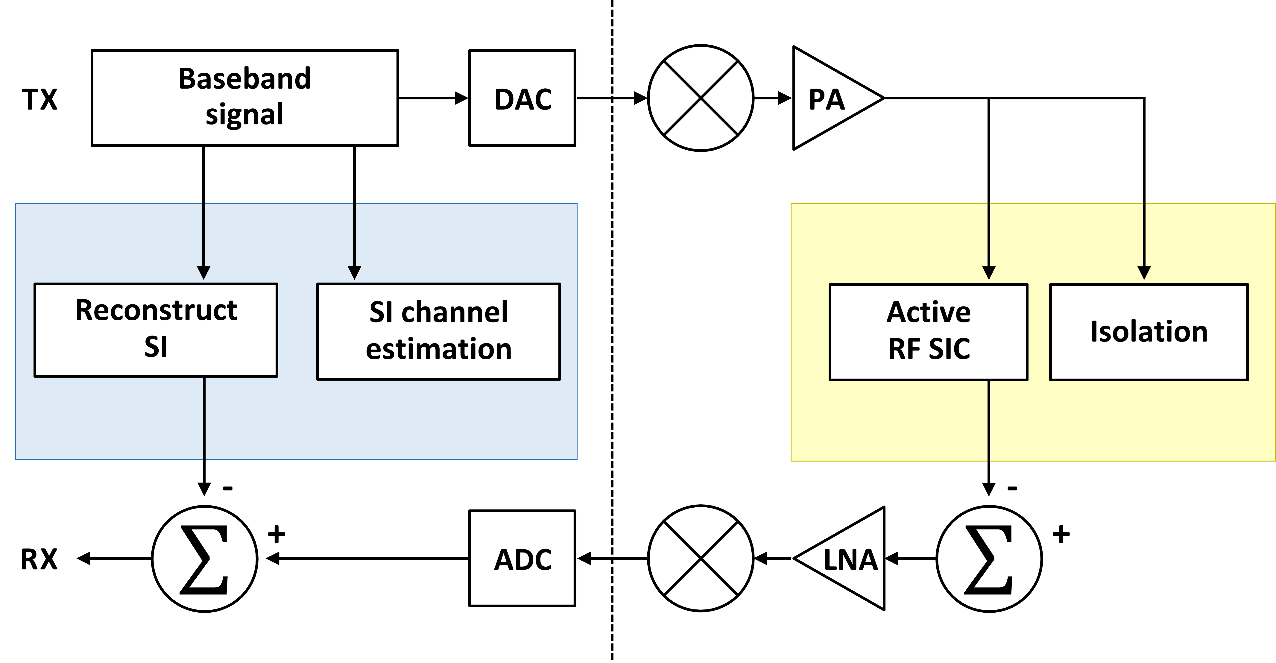
Channel estimation-based cancellation can be carried out in both analog and digital domains. The cancellation procedure consists of three steps: (1) modeling the SI channel, (2) estimating the SI channel using perfect knowledge of the transmit signal, and (3) reconstructing and subtracting the SI from the received signal. Linear components of SI can be easily mitigated by existing channel estimation methods. Nonlinear components such as power amplifier nonlinearity and I/Q imbalance can be modeled as described in references [35, 36]. The primary challenge of SIC is the required dynamic range of the ADC to acquire both the SI and signal-of-interest simultaneously. For instance, with a 14-bit ADC, the dynamic range is 86 dB,111A dynamic range of a -bit ADC is calculated as which implies that the SI power after analog cancellation must not exceed the receiver noise floor by 86 dB. Fig. 1 demonstrates the power levels in a successful SIC scenario. The ADC’s dynamic range determines the amount of required analog cancellation, which is typically not achievable with intrinsic cancellation alone. As a result, most full-duplex systems use additional active cancellation in the analog domain, which is also based on SI channel estimation. A full-duplex system that combines analog and digital domain SIC is shown in Fig. 2.
II-A Passive Analog SI Cancellation
In the propagation stage, an isolator can be used to separate the desired signal and the SI. Passive analog cancellation, which does not require an active RF component, is often employed in this stage. One approach is to use separate antennas for the transmit and receive chains, which can be described in terms of path loss between the two antennas as
| (1) |
where , , and denote the path loss exponent, the distance between the two antennas, and a system-dependent constant, respectively. Clearly, as (1) indicates, the SIC amount is determined by the size of the FD transceiver (specified by ).
Another analog SIC solution relies on antenna cancellation via using an additional transmitter (TX) (or receiver (RX) antenna), aiming to generate a -phase rotated SI signal at the RX of the FD transceiver [11]. Let us denote the wavelength of the transmitted signal by . Suppose also that the distance between a TX antenna of the FD radio and its RX is larger than the distance between its TX and RX. In this case, considering also line-of-sight signal propagation, the two transmit signals will arrive with a phase difference of at the RX. To compensate for the different path loss, we have to allocate more power to the TX . This transmission scheme implies that the SI signal will be perfectly mitigated, because the signal from the two transmit antennas will add destructively at the receive antenna. The authors in [9] adopted interference cancellation for this antenna-based SIC scheme. Note that, since it depends on wavelength , this asymmetric antenna cancellation method is inherently applicable in narrowband systems.
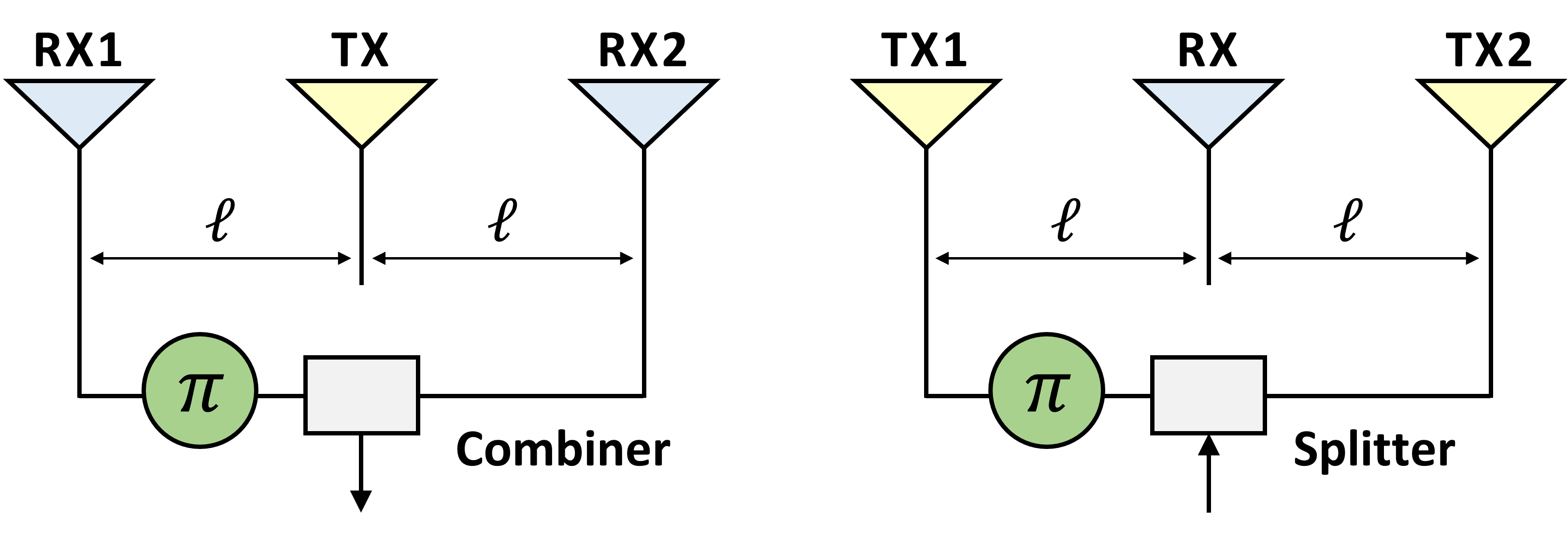
To alleviate the dependency on the narrow bandwidth assumption, a symmetric antenna cancellation scheme was presented in [16, 11]. The antenna system architecture for such an FD system is demonstrated in Fig. 3. As shown, a -phase shifter is employed instead of having space separate TXs. It should be emphasized here that we can mitigate SI by using two RX antennas and one TX antenna. The -phase shifter is placed after one of the RX antenna as illustrated in Fig. 3. In [37, 38], passive analog SIC techniques using polarized antennas were proposed, while [38] experimented with an FD-based Long Term Evolution (LTE) prototype including a dual-polarized antenna.
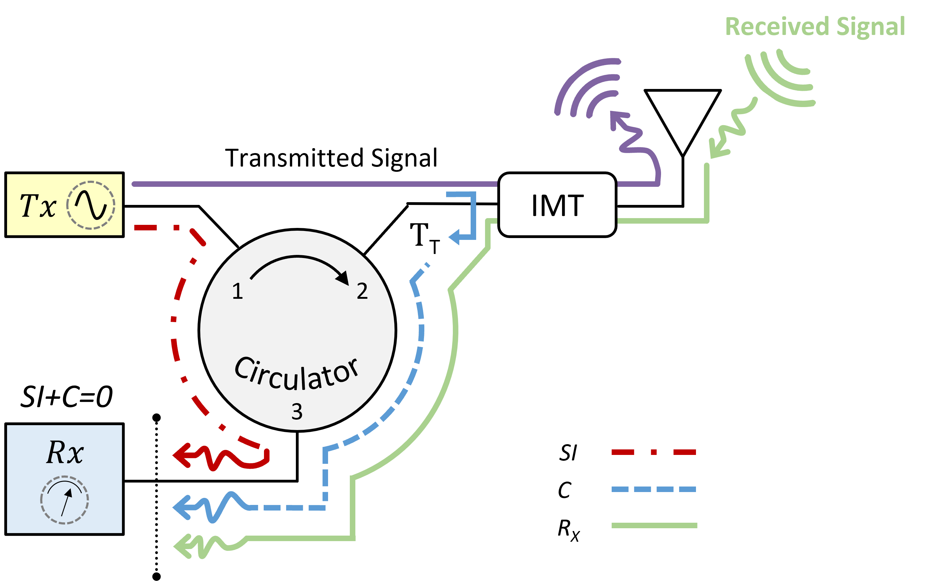
To achieve passive analog SIC in FD radios utilizing the same antenna for simultaneous transmission and reception, one needs a circulator. It is noted that circulators can provide isolation only for narrow bandwidths. As shown in Fig. 4, this is a -port device (TX, antenna, and RX ports) that steers the signal entering any port to only the next port; ferrite circulators are often used in communication systems. When a signal enters to Port , the ferrite changes a magnetic resonance pattern to create a null at Port . The resulting SI components from a circulator are sketched in Fig. 4.
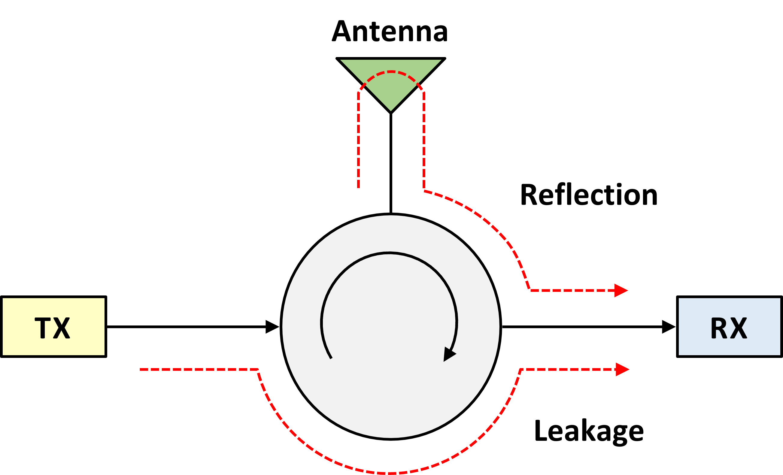
As shown, the strongest SI component comes from the direct leakage, with a typical circulator being capable to provide and up to dB isolation for this signal. The remaining SI components can mitigated using active analog SIC, as will be described in the sequel. The second signal component contributed by the circulator is the signal reflected by the antenna. Its reflected power (a.k.a., return loss) can be computed in dB as follows:
| (2) |
where and represent the load (i.e. receiver, transmitter and circulator) and the source (i.e. antenna) impedance, respectively. Finally, the third component resulting from the deployment of the circulator is a reflected signal from the environment that depends on the objects lying in the proximity of the FD system.
Passive analog SIC has a major drawback in that it cannot eliminate the SI signal resulting from reflections from the environment. In [39], the researchers compared the residual SI after passive cancellation in both an anechoic chamber and a highly reflective room with metallic walls. To address this issue, they used a combination of directional isolation, absorptive shielding, and cross polarization. The absorptive shielding involved placing an RF-absorptive material between the TX and RX of the FD system to increase path loss. They used Eccosorb AN-79 as the absorber, which consists of discrete layers of lossy material and has an impedance designed to be similar to air. The impedance gradually increased from the incident layer to the rear layer, making the multi-layer structure more effective at absorbing electromagnetic waves over a broad frequency range than the single-layer structure used in [39]. These findings suggest that active cancellation, in combination with passive suppression, may require higher-order filters or per-subcarrier cancellation.
II-B Active Analog SI Cancellation
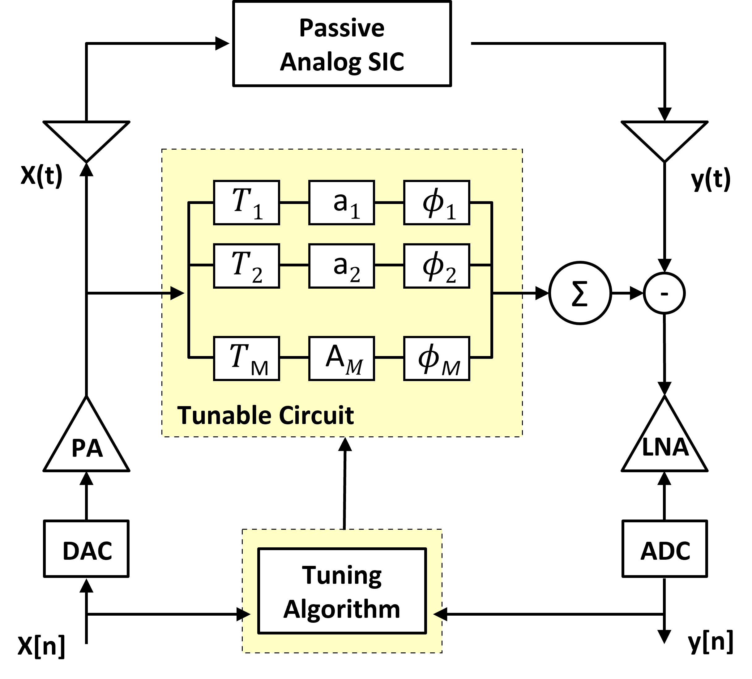
Active analog SIC targets at generating a signal that matches to the usually unavoidable leakage from the passive analog SIC. This is done by using a dynamically tunable circuit mimicking an auxiliary transmit RF chain [15, 40], which is fed with a copy of the transmitted signal. A general multi-tap analog SI canceller consisting of delay line is illustrated in Fig. 5. As shown, each -th delay line, with , comprises an attenuator and a phase shifter . The triplets of analog cancellation parameters are configured via solving the following optimization problem:
| (3) |
where denotes the output signal of each -th delay line that will be a function of its tunable parameters, and is the leaking signal at the output of the passive analog SIC. In Fig. 5, represents the transmitted signal, resulting from the baseband version when it passes through the transmit RF chain. The paper [41] introduces the use of neural network machine learning to accelerate the tuning of multi-tap adaptive RF cancellers. In an analogous way, is the baseband transformation of , when the latter feeds the receive RF chain. It is noted that the optimization problem (3) is performed in the digital domain (i.e., the optimization algorithm receives as input variables the baseband signals and ). Recall that the aim of the analog SIC is to avoid the ADC saturation. Therefore, at an initial phase, the SI signal is transmitted at a weak power to carry out the optimization (i.e., tune the active analog SIC circuit), while avoiding ADC the saturation. When the parameters are set, the FD transmission is performed.
To eliminate the two main sources of interference in SI leakage, an adaptive circuit must be developed when using a circulator as a passive isolator. This circuit should incorporate delay lines with variable attenuators to fix the delays using the properties of the leakage [42, 43]. By selecting appropriate fixed delays, the original SI can be regenerated even if it has arbitrary delays within a particular range. Using fixed delays in this way eliminates the need for high-resolution delays, making the proposed approach more feasible to implement.
With a similar objective in mind, the authors of [44, 45] adopted a straightforward approach by utilizing an impedance mismatched terminal (IMT) circuit and the secondary SI signals inherent at the circulator (i.e., those reflected by the antenna), to nullify the primary SI signals that leaked from the TX to the RX port. They modified the frequency response of the secondary SI signals, referred to as , by employing a reconfigurable IMT circuit with two varactor diodes at the antenna port, as shown in Fig. 6. By controlling the bias voltages of those diodes, the frequency band and bandwidth were adjusted. The IMT adjustability made it resilient to fabrication errors and antenna input impedance variations. The proposed method achieved a cancellation of more than dB over MHz bandwidth at GHz.
II-C Digital SI Cancellation
II-C1 Filtering
Digital-domain SIC can be accomplished via by SI regeneration using digital filters fitted to the detector input through the known transmitted data. A key challenge for this cancellation is the nonlinear distortion introduced at the TX and RX. The effect of the transmit and receive power amplifier nonlinearities on the digital SIC techniques was analyzed in [46], whereas the impact of the in-phase/quadrature (I/Q) imbalances and the resulting image components were investigated in [47]. Signal models including the phase noise at the TX and RX oscillators were presented in [48]. It was observed that the phase noise is a bottleneck for perfect SIC while using two different oscillators for transmission and reception. A scenario with a common oscillator for both the TX and RX sides was also analyzed in [49]. A comprehensive SI model for single-antenna FD radios, considering all impairments including the TX and RX I/Q imbalances, nonlinear distortions in all the transceiver components, RX’s noise figure, and the phase noise effect at both TX and RX I/Q mixers was provided in [50].
II-C2 Linearization via Deep Neural Networks
All of the aforementioned digital SIC techniques require knowledge of the nonlinear model prior to implementation, including the order of a polynomial model. In contrast, DNN-based solutions, such as those proposed in [51, 52, 53, 54, 55, 56], do not require prior knowledge of the nonlinear distortion model. Additionally, it has been demonstrated in [51, 56, 57] that the use of a DNN can reduce computational complexity by up to when compared to non-DNN-based solutions [58]. Most current DNN-based methods combine estimation of the typically time-invariant nonlinear distortion and the time-varying SI propagation channel, which must be periodically re-acquired. As such, these approaches require online training, since they do not make use of information from previous time intervals. This can be addressed by decoupling the time-varying SI propagation channel from the estimation of the time-invariant nonlinear distortion and utilizing transfer learning to combine elements of both off-line and on-line training while accumulating information across time intervals [59, 60].
II-D MIMO Architectures and Spatial SI Cancellation
Spatial signal processing schemes, based on the multiple-input multiple-output (MIMO) technology, can be used to suppress the SI signal to desired levels, and have been usually deployed in conjunction with any of the previously described analog and digital SIC techniques [20, 62, 17, 63, 64]. In the available FD MIMO transceiver architectures, which intend to profit from the diversity or multiplexing gain offered by the efficient usage of the multiple antennas, the spatial degrees of freedom can be used to simultaneously handle the SI signal as well as the downlink (DL) and uplink (UL) signals of interest. It is noted, however, that more SI signals are inevitably generated due to the larger number of antenna elements at an FD node’s TX side, that need to be efficiently suppressed. To this end, FD MIMO targets to balance between the received signal quality and SI suppression, and various techniques have been lately presented, namely, null-space projection or transmitting and receiving in orthogonal subspaces [20, 65, 66, 67, 68], antenna selection for choosing the best pair or subset of TX/RX antennas minimizing the SI [69, 70, 71, 72], joint TX and RX beam selection [73, 74], use of lenses [75], and zero-forcing (ZF) beamforming for SI elimination [69, 76, 77] or minimum mean squared error (MMSE) filtering that maintains the useful signal’s quality [78, 79, 80, 81, 82].
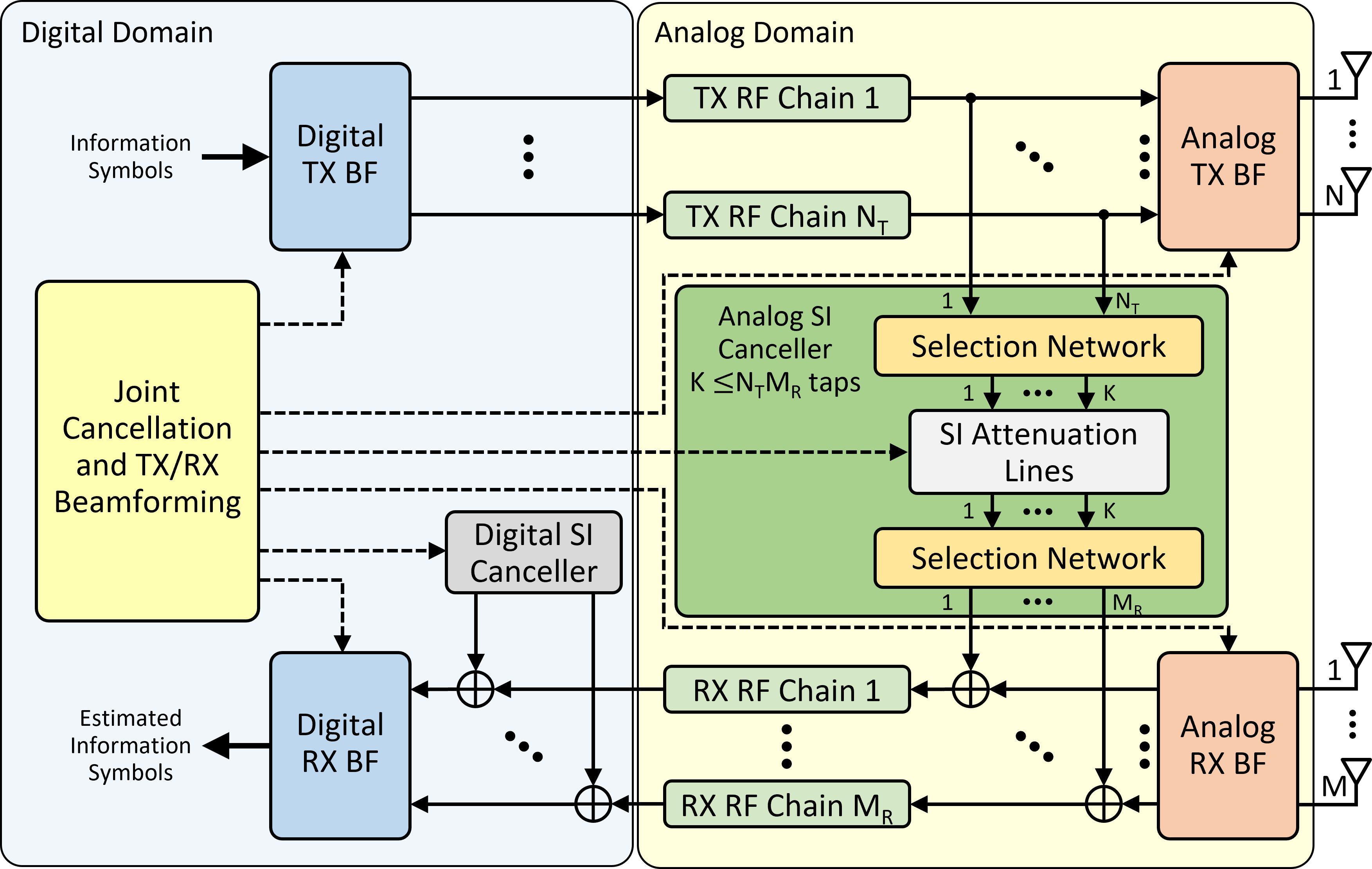
The generic unified FD MIMO transceiver architecture of Fig. 7 was recently presented in [73, 61] for the case of TX and RX antennas, where any of the and can be arbitrarily large. All TX antenna elements are attached to TX RF chains, and all RX antenna elements are connected to RX RF chains. A TX RF chain consists of a digital-to-analog converter (DAC), a mixer which upconverts the signal from baseband to RF, and a power amplifier. An RX RF chain consists of a low-noise amplifier (LNA), a mixer which downconverts the signal from RF to baseband, and an ADC converter. The RX side of the architecture in Fig. 7 is composed of analog RX beamforming connecting the RX antennas with the inputs of the RX RF chains, and digital RX beamforming that processes the outputs of the RX RF chains in baseband before symbol decoding. Similar to the TX side, each of the RX RF chains is connected to a sub-array of (again, assumed integer-valued) antenna elements via constant-magnitude phase shifters. The complex-valued analog RX beamforming vectors belong in a predefined RX beam codebook, similar to the analog beamforming ones. The signals at the outputs of the receive RF chains are being downconverted and fed to the digital RX beamformer to derive the estimated information symbols. As previously described, the objective of SIC in FD radios is to suppress the SI signal below the RX noise floor. In practical wireless communication systems, each receive RF chain is characterized by a maximum input signal power level, above which saturation happens. This means that when the SI signal is larger than the chain’s maximum allowable power level, this RX RF chain gets saturated. The role of the active analog SIC is to suppress the SI signal power level below the latter threshold in order to avoid saturation.
Several variations of the MIMO architecture in Fig. 7 were investigated over various hardware impairments in [78, 79, 80, 81]. A active multi-tap wideband analog SIC architecture, whose number of taps does not scale with the number of transceiver antennas and multipath SI components, was presented in [83]. An alternative architecture for the analog canceller, which is based on auxiliary TXs for locally generating the SIC signal, was presented in [84]. An extreme case of the unified architecture in Fig. 7 relies solely on TX digital beamforming to reduce SI at the RX antennas of the FD node, without making use of any analog SIC [65, 85]. In addition, [86] studied two methods of partial active analog SIC: the one, where the analog cancellers are assigned to a fixed set of antennas, and the other, where the cancellers are reconfigurable such that they can be dynamically assigned to any RX antennas based on the channel conditions.
As shown in Fig. 7, SI attenuation lines appear in the analog SIC, which also includes two selection networks. The role of these networks is to decide which SI signals will be mitigated from which inputs to the RX RF chains. In [78], the selection network feeding the inputs to the SI attenuation lines was implemented with MUltipleXers (MUXs) of -to-, while DEMUltipleXers (DEMUXs) of -to- were considered for implementing the selection network at the outputs of the attenuation lines. Each attenuation line can be realized via a fixed delay, a variable phase shifter, and a variable attenuator, termed also compactly as an analog tap [78], or with an auxiliary TX for locally generating the SIC signal [84]. The adders appearing before the RX RF chains in Fig. 7 can be implemented via power combiners or directional couplers.
The conventional FD MIMO architectures of [20, 62, 64] deploy fully-connected analog SIC, which interconnects all inputs to the TX antennas to all outputs of the RX antennas in order to suppress all possible SI signals. This cancellation approach requires SI attenuation lines. In the recent architecture of [87], the active analog SIC connects all outputs of the TX RF chains with all inputs to the RX RF chains, which results in attenuation lines. Clearly, when or , the architecture of [87] has the lowest complexity analog SIC. However, an algorithmic design for the parameters of the attenuation lines as well as for TX/RX beamforming to justify improved performance with the fully-connected architectures of [20] was not presented in [87].
The FD MIMO architectures in [88, 89, 90, 91] adopt also fully-connected analog TX/RX beamforming, which results in large numbers of phase shifters, as compared to the partially-connected architecture in Fig. 7. The architectures in [88, 89] include active analog SIC with taps, i.e., the canceller’s hardware scales with the product of the TX and RX antennas. This complexity is prohibitive for FD massive MIMO systems. The paper [92] presents a neural network structure that exploits the spatial correlation among the transmit and receive antennas to reduce the complexity of echo cancellation filters at the receivers. In [90] and [91], passive SI suppression was used instead of analog SIC. However, it has been shown that only digital TX/RX beamforming falls short in efficiently handling nonlinear SI resulting from TX impairments. The architecture in Fig. 7 deploys active analog SIC with taps (i.e., its complexity does not scale with the number of TX/RX antennas, hence, suitable for massive MIMO), which is jointly designed with the analog and digital TX/RF beamformers.
III Current Applications and Trends
In this section, we present the latest applications and trends of the in-band FD technology, highlighting the unique opportunities offered by its STAR operation as well as the technical challenges that need to be addressed for each application’s consideration for future wireless systems. We particularly discuss FD for sensing, ISAC, IAB, latency reduction, its potential inclusion in the upcoming 5G-Advanced, interplay with the emerging wireless technology of reconfigurable metasurfaces and how NTNs for ubiquitous connectivity could benefit from it.
III-A Wireless Networks That Sense
Opportunity: In current and next generation wireless networks, higher spectral bands are of significant interest, e.g., millimeter wave (mmWave) bands and above. Interestingly, those bands have been extensively used for sensing, e.g., automotive radars, airport security systems, and quality control in manufacturing. Thus, the use of such frequencies for wireless networks opens new possibilities for leveraging the same hardware and network infrastructure for both sensing and communications [93, 94]. As a result, driven by efficient spectrum usage and enabled by the deployment of advanced antenna systems at cellular base stations, integrated or harmonized communication and sensing systems are gaining renewed interest both by the academic and industrial research communities [95, 96, 97].
State-of-the-art: In recent years, there has been significant activity in developing algorithms and establishing practical feasibility investigations in the broad area of wireless sensing. For example, several works on human sensing have demonstrated ability to sense heart rate, gait, or gestures using wireless signals [98, 99]. That body of work has also shed light on the differences between sensing and channel estimation; sensing appears to be a form of channel estimation that is commonly performed in all wireless systems. The difference between the latter two lies in the details about the physical medium that is modeled to address communication and sensing objectives [100]. The aim of communication is maximal energy transfer from a source to a sink via the channel between them. Hence, the channel models need to capture how the energy transfer from an TX to and RX occurs, e.g., often modeled as a linear transfer function that does not distinguish between different objects in the scene. On the other hand, different sensing objectives explicitly model specific scene properties of interest. For example, radar sensing models the location and velocity of the targets of interest in the environment [101], [98] and human sensing models specify human-focused parameters, like heart rate and gait [99].
Challenges: Three sensing architectures, namely mono-static, bi-static, and multi-static sensing, as illustrated in Fig. 8, that are based on the location and number of TXs and RXs, are of practical interest. Two metrics of interest in sensing are that of the sensing accuracy and sensing coverage; these are equivalent to the communication systems’ metrics of error probability and cell coverage.
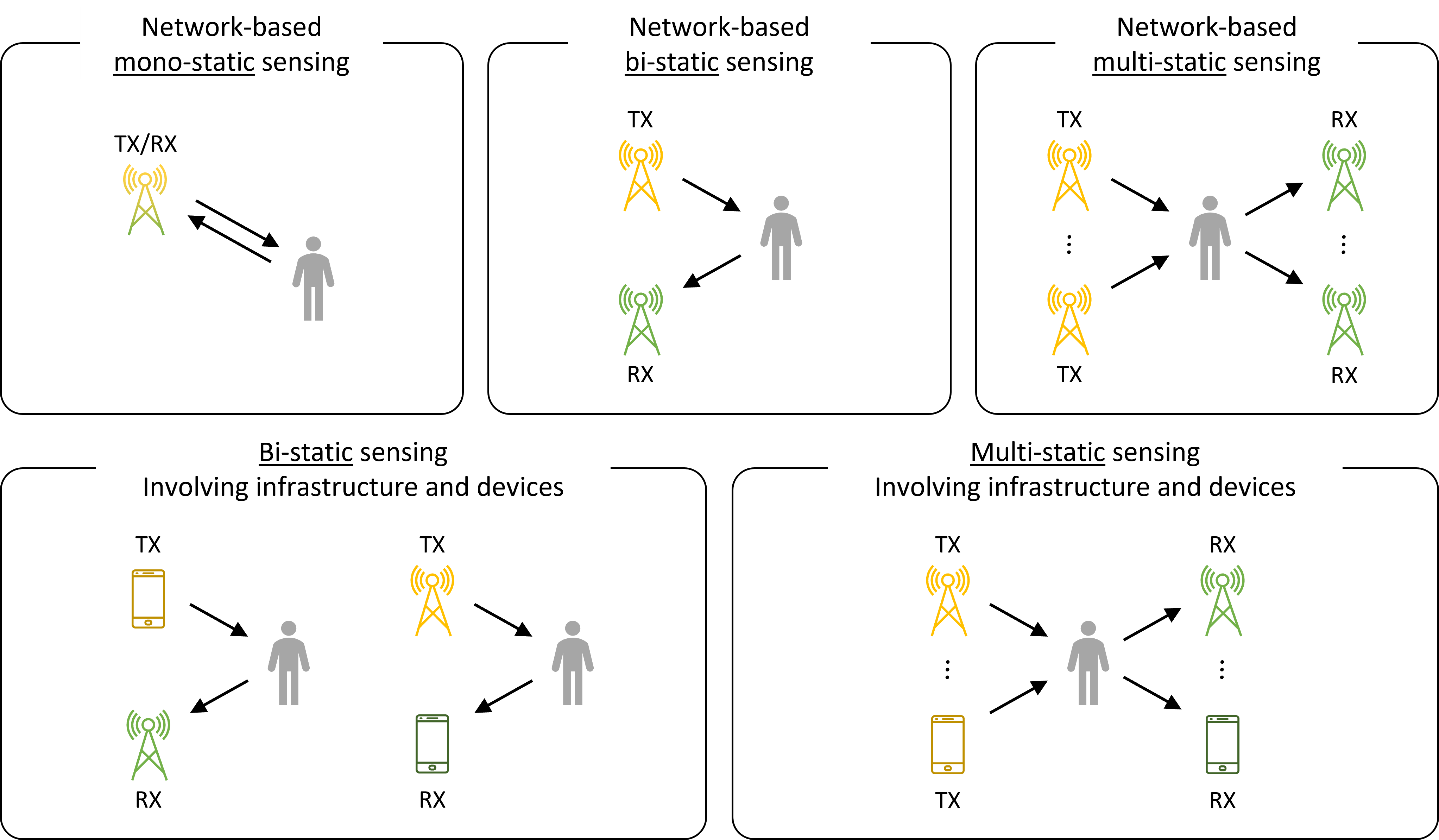
In the architecture of mono-static sensing, the TX and RX are co-located. This architecture is commonly used in radar sensors. The co-location of a TX and RX allows time and frequency synchronization, enabling the highest sensing accuracy. For sensing applications where the distance to a target is of the order as that witnessed in wireless networks, mono-static sensing requires in-band FD operation. However, when conventional SIC is applied, all useful information for sensing is removed. To this end, a key challenge in developing mono-static wireless sensing is to retaining backscatter, while cancelling out SI or reflection paths that do not provide any sensing information. Recent theoretical results [102] demonstrate that multipath could potentially be used to increase performance of monostatic sensing.
The second architecture is bi-static sensing, where the TX and RX cannot be time and frequency synchronized, which is often the case when the two communication ends are physically not co-located. The lack of synchronization creates a significant challenge, which has to be accounted for in the design of sensing algorithms. Overall, the sensing accuracy is lower in bi-static architectures than mono-static ones. However, the bi-static architectures do not require FD operation, and hence, can leverage existing hardware capabilities of radio transceivers
The last sensing architecture is multi-static sensing, which is a generalization of bi-static sensing to allow arbitrary number of TXs and RXs to participate in sensing. The sensing coverage of multi-static sensing is (by definition) higher than mono- and bi-static systems, as it can illuminate more of the scene and capture larger portions of reflected energy. However, this gain in sensing coverage requires coordination in transmission and joint processing of received signals, which is a major challenge in mobile wireless networks.
III-B Integrated Sensing and Communication (ISAC)
Opportunity: The emerging concept of ISAC, according to which the previously competing sensing and communication functionalities are jointly optimized in the same hardware platform using a unified signal processing framework, is lately gaining increased attention from both academia and industry for future wireless networks [103, 104, 105]. In-band FD is being considered as a key enabling technology for ISAC applications due to its STAR capability, with promising theoretical results demonstrating advantages of joint design [106].
State-of-the-art: In [107, 108], single-antenna FD systems were considered for ISAC operation, where both communication and radar waveforms were optimized for sensing performance. Frequency-domain radar processing building on the‘ LTE or the 5G New Radio (NR) time–frequency resource grid, and complemented with interpolation to account for missing samples due to the null subcarriers within the transmit waveform passband, was presented in [107]. It was shown that the large channel bandwidths supported by 5G NR provide good sensing performance already at below GHz frequencies. With MHz channel bandwidth, range estimation accuracy in the order of m and target detection probability exceeding were shown to be feasible at signal-to-noise ratio (SNR) values lower than dB. To prevent RX saturation in mono-static shared-antenna BS deployments and reduce the inherent masking effect of the direct leakage sidelobes, efficient analog and digital SIC solutions, tailored to the orthogonal frequency division multiplexing (OFDM) radar use, were introduced in [107]. The various provided measurements verified successful sensing of static and moving targets, such as drones and cars, while evidencing measured TX/RX isolation at the FD node of approximately dB.
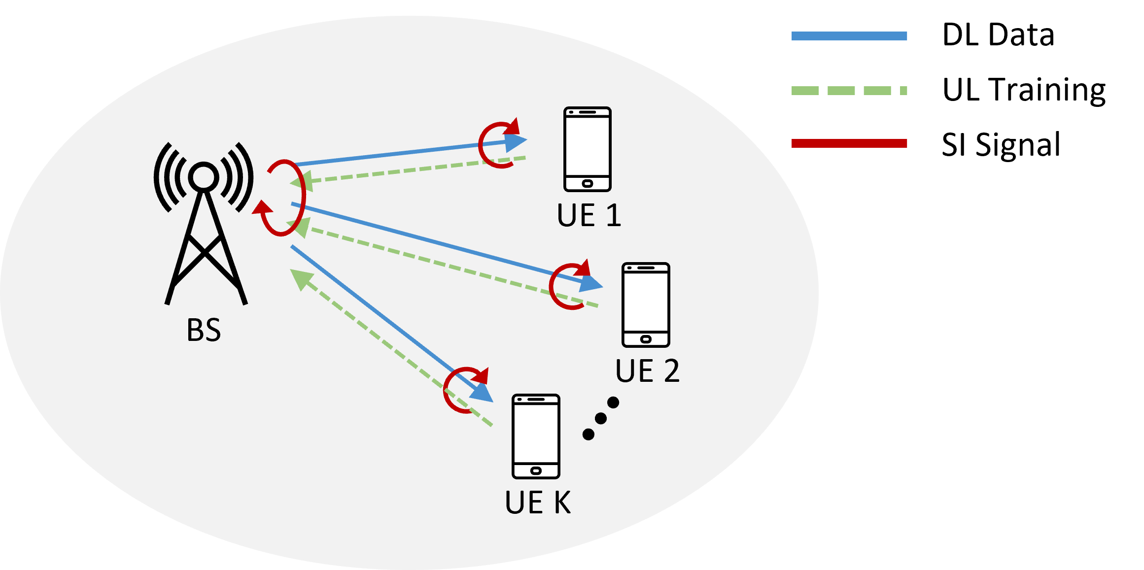
Apart from the typical optimization of the UL and DL sum rate, FD radios have been considered to continuously update the channel state information at the transmitter (CSIT), which is required to compute the DL precoding matrix in multi-user (massive) MIMO systems, as schematically shown in Fig. 9. By design principle, FD operation leverages channel reciprocity for open-loop UL training to estimate the DL channels. However, the UL transmission of training might create interference at the DL receiving mobile nodes. Most predominantly, the DL transmission contaminates the reception of the training symbols in the UL. For this channel sounding process based on FD systems, the optimal training resource allocation and its associated spectral efficiency was studied in [109, 110, 111, 112]. In particular, simultaneous DL data transmission and UL channel state information at the receiver (CSIR) has been considered for an FD MIMO BS serving multiple HD UE. The latter were assigned to transmit training symbols through the UL channel in a time division multiple access manner, which are utilized by the BS to estimate the DL channels, while at the same time transmitting the DL payload to the user for whom the CSIT is already available. The adopted multi-user FD system models in [109, 110, 111] deployed ideal active analog SIC that was based on MIMO architectures with fully-connected analog SIC, interconnecting all TX antenna elements in the FD node with all its RX antennas. Recently, in [113, 114], the reduced complexity acive analog SIC of [78] was adopted to jointly design the BS’s transmit and receive BF matrices, as well as the settings for the multiple analog taps and the digital SI canceller, with the objective to maximize the DL sum rate. It was showcased that the proposed approach outperforms its conventional HD counterpart with reduction in the hardware complexity of the analog canceller compared to the schemes in [109, 110, 111].
FD MIMO radios have been also leveraged for efficient low-latency beam management in mmWave MIMO systems. In particular, [115] presented a direction-assisted beam management framework, where the BS was equipped with a large antenna array realizing DL analog beamforming and few digitally controlled reception antenna elements used for UL estimation of the direction-of-arrival (DoA) of the UL signal from an intended UE. A simultaneous DoA estimation and data transmission scheme for boosting beam management was presented, capitalizing on the FD MIMO architecture of [78]. Leveraging channel reciprocity, the UL dominant DoA was estimated at the FD BS, which then transmits analog beamformed data in the estimated DL direction. A joint design of the DoA-assisted analog beamformer as well as the active analog and digital SIC units was proposed with the objective to maximize the achievable DL rate.
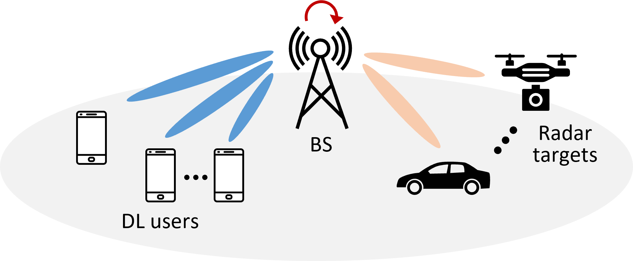
A multi-beam mmWave FD ISAC system was presented [116], according to which the TX and RX beamformers were optimized to have multiple beams for both communications and sensing, as schematically presented in Fig. 10. The proposed optimization targeted at suppressing the SI signal arising from the FD operation, and the sensing performance was further improved by minimizing the reflections from the communication beams; the latter was accomplished by implementing beamforming nulls in both the frequency and angular domains. In addition, an OFDM waveform design, through filling the unused subcarriers with optimized symbols, was designed, which was shown to minimize the delay estimation error, while also minimizing the peak-to-average power ratio of the waveform. In [117, 118], the RX spatial signal was further used to estimate the range and angle profiles corresponding to the targets. Very recently, in [119], the authors presented an ISAC system where a massive MIMO BS equipped with hybrid analog and digital beamformers is communicating with multiple DL users, and simultaneously estimates via the same signaling waveforms the DoA as well as the range of radar targets, which are randomly distributed within its coverage area. A joint radar target tracking and DL data transmission protocol was presented together with an optimization framework for the joint design of the massive-antenna beamformers and the SIC unit, with the dual objective of maximizing the radar tracking accuracy and DL communication performance. The provided simulation results at mmWave frequencies, using 5G NR wideband waveforms, showcased the accuracy of the radar target tracking performance of the proposed system, which simultaneously offered increased sum rate compared with benchmark HD schemes. A more involved joint optimization framework for designing the analog and digital TX and RX beamformers, as well as the active analog and digital SIC units, was presented in [120] with the objective to maximize the achievable DL rate and the accuracy performance of the DoA, range, as well as the relative velocity estimation of radar targets. The simulation results, considering 5G NR OFDM waveforms, showcased high target parameters’ estimation accuracy, while maximizing the DL communication rate.
Challenges: In multi-function networks enabling ISAC, several important design aspects need to be considered, namely, the choice of the sensing architecture, the signal design for each functionality, and the resource sharing between the communications and sensing operations.
III-B1 To Mono or Not
In a tightly ISAC system, a key design question is whether sensing should utilize a mono-static or bi-static setup, as illustrated in Fig. 8. Mono-static operation together with continuous time radar signals imposes the requirement for sophisticated FD operation with adequate SIC. In some cases, the FD requirement can be avoided by using pulsed radar signals, rather than continuous-wave signals, which use long silent periods of post-transmission to allow for the interference-free reception of the echo signals. Alternatively, when using continuous-wave signals, the known TX signal can be used as “template signal” to detect only the difference between the transmitted and received signals, and estimate the parameters of this “beat” signal [93]. In a bi-static radar setup, the FD requirement is eliminated at the expense of a stringent synchronization problem, that applies to both the timing and frequency offsets between the oscillators of the TX and RX nodes. In practice, mono-static and bi-static sensing can be advantageously employed simultaneously when sensing is integrated in the operation of cellular networks, depending on the duplexing scheme of the network. For example, in 5G NR systems operating in TDD mode, mobile terminals (i.e., UE devices) obtain channel state information by means of synchronization signal blocks transmitted in a physical broadcast channel (PBCH), while the BS may acquire information about the communication channel by decoding the sounding reference signals (pilots) sent periodically by the mobile terminals. Due to channel reciprocity, the channel state information obtained by the BS serves as CSIR and CSIT facilitating both UL data reception and DL data transmission, respectively. In this operation, mono-static sensing is conveniently integrated in the DL frames, while bi-static sensing can be optionally added to utilize the UL pilot or data signals to enhance the sensing precision at the BS.
III-B2 From SIC to SI Management
As discussed above, in mono-static DL sensing, the BS transmits the same signal to multiple UE devices, while having its RX active for backscattered signals to sense its surroundings. That is, sensing information is completely contained in the backscattered signal. However, in FD communications, the backscattered signal is an SI signal that has to be eliminated to improve communications. Thus, SIC developed for communications could potentially remove the key signals required in sensing. Thus, an open question for ISAC networks is how to manage backscattering, i.e., it remains to understand which part of the backscattered signal to suppress and which to admit. To enable mono-static DL sensing, it is necessary to admit reflections from the surrounding objects and not cancel useful backscattered signals, while ensuring sufficient TX/RX isolation [121, 107]. To enable ISAC using mono-static radar, more than dB of total SI suppression is required, which calls for multiple complementary methods, since no single technique can facilitate such high TX/RX isolation at FD devices. Therefore, in addition to basic passive analog SIC and radar-domain digital suppression methods, efficient active analog and digital SIC methods are needed, particularly from the static and slow-moving targets’ viewpoint, as well as overall, to prevent RX saturation [107]. To this end, active analog and time-domain digital SIC methods are important. Compared to the existing in-band FD radio research, a specific radar-related aspect is that only the direct SI should be canceled or suppressed, along with possible reflections from very close surfaces, while the echoes from the targets of interest must be properly detected. This aspect is an important difference to FD radio works developed solely for communication networks, such as that in [122], which does not distinguish between the direct and reflected SI components. In addition, agnostic digital SIC techniques, independent of the specific radar processing approach, are desirable, which can then be complemented with SIC methods operating in the radar domain [123].
III-C Integrated Access and Backhaul (IAB)
Opportunity: Future cellular networks are expected to be highly dense to support extended coverage and capacity expansion. However, traditional fiber-backhauling can be expensive. To address this, a new technology called Integrated Access and Backhaul (IAB) has been developed, which integrates access and backhaul functions using wireless links. IAB was included in the 3GPP NR Release 16, and the work on IAB was finalized in 2020 [124].
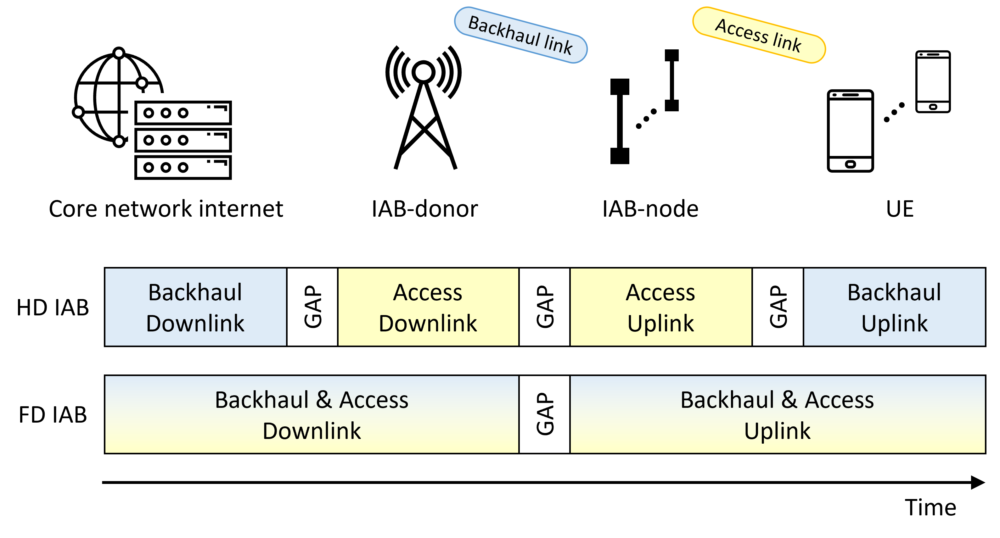
State-of-the-art: A typical IAB architecture, where only some of the gNBs (generation Node B) are connected to the traditional wired infrastructures (core network internet) via fiber as IAB-donors, while the rest of them, termed as IAB-nodes, decode and forward the backhaul traffic wirelessly, is illustrated in Fig. 11. It is noted that an gNB BS provides NR protocol terminations to UE. As defined in 3GPP technical specification [125], the gNB is a logical node, which may be split into one central unit (CU) and one or more distributed units (DU). The CU hosts the higher layer protocols to the UE and terminates the control and user plane interfaces to the core network. The CU controls the DU nodes over the F1 interface(s), where the DU node hosts the lower layers for the NR Uu interface to the UE. The conventional scenario in Fig. 11, which we refer to as HD IAB, involves an in-band system in which the backhaul and access links share the same frequency spectrum under the typical HD constraints. In other words, the access and backhaul links must use the given radio resources in an orthogonal manner, be it time or frequency, to avoid collision. Thus, HD-based IAB clearly fails to exploit the full potential of the given radio resources.
In contrast, researchers have proposed a smarter IAB framework, referred to as FD IAB, that eliminates the HD constraint and enables simultaneous transmission and reception of backhaul and access links. With advanced FD capability and proper SI mitigation, FD IAB can achieve a spectral efficiency more than double that of the conventional HD IAB scenario, as illustrated in Fig. 11. Additionally, FD technology can reduce end-to-end and feedback delays and provide more degrees-of-freedom in wireless protocol design [126].
Challenges: As previously discussed, to realize FD IAB in practice, and then include into the future 3 Generation Partnership Project (3GPP) releases, it is necessary to verify the performance of the system.
III-C1 Link-Level Simulations
Although FD IAB has a promising future, SI mitigation is a crucial challenge. Since SI increases with TX power, deploying IAB-nodes with high TX power infrastructures requires state-of-the-art SI reduction performance. In a macrocell scenario, the transmit power at the IAB-DU can be as high as SI 46 dBm, which means that more than 120 dB of aggregate SI reduction is necessary to reduce the SI close to the RX noise floor. This is a significant technical challenge that needs to be addressed for the successful deployment of FD IAB.
The strict performance requirements have led some to question the feasibility of implementing FD in infrastructure systems. Nevertheless, exploiting highly directional beams in the millimeter wave band can lead to significant suppression of SI in the propagation domain, making FD feasible. In the subsection that follows, we provide link-level performance evaluations based on a realistic configuration of an IAB system.
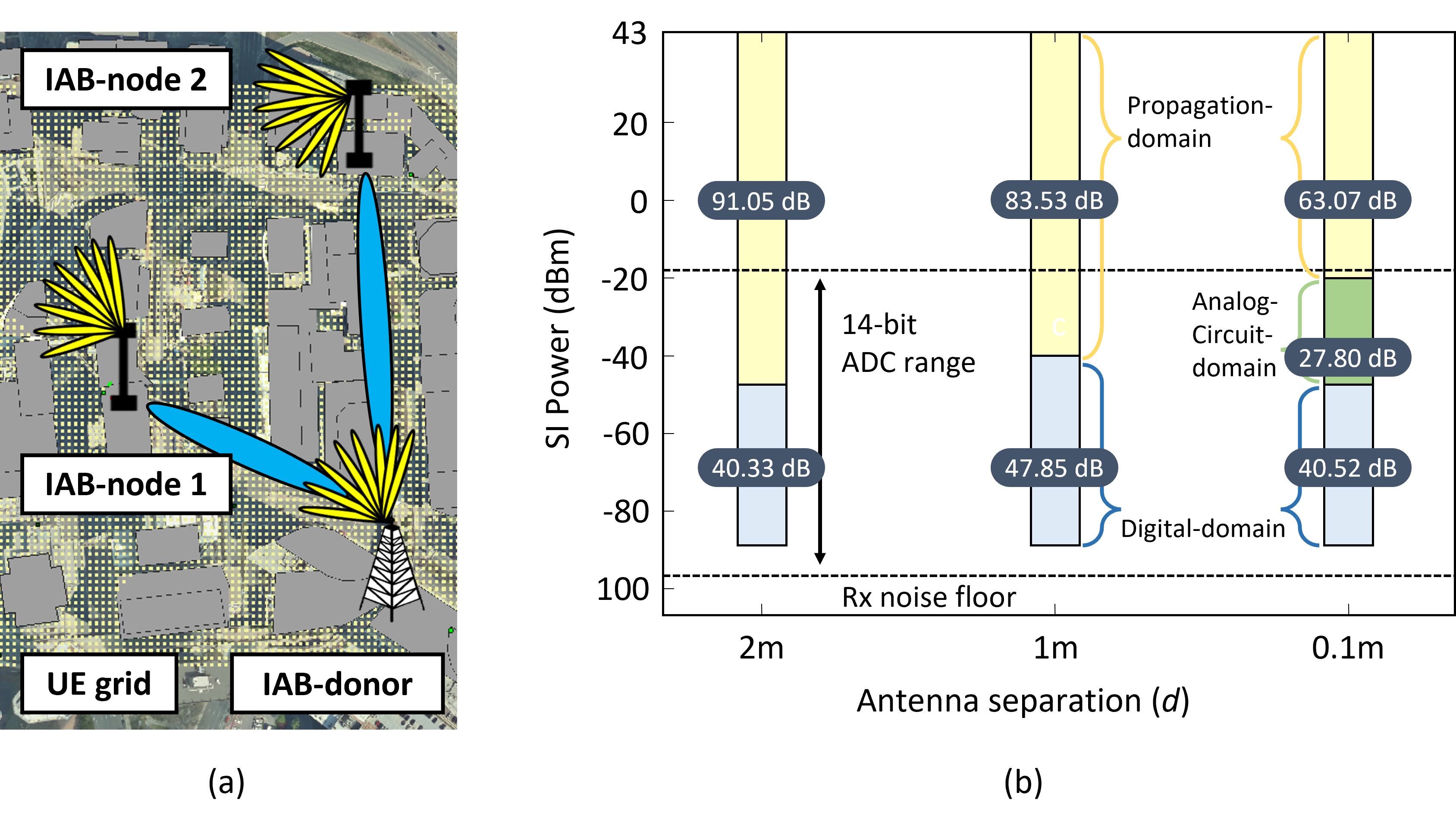
Fig. 12 presents the results of link-level simulations conducted in a virtual 3D environment modeling the downtown area of Rosslyn City, Virginia, USA, using realistic settings. The simulation considers an in-band FD IAB scenario, with physically fixed relays equipped with a narrow beam codebook and an RF chain at both the DU and mobile termination (MT)222It should be noted that the backhaul links are terminated by an IAB-MT function [125]. The IAB-MT could either use a separate antenna or share the access antenna of the BS (virtual IAB-MT). The latter provides the ultimate level of integration, as well as utilizing the high-performance BS antennas for backhaul over longer distances, operating over a 120 MHz bandwidth channel at the central frequency of GHz is considered.
The setting includes a IAB-donor and two IAB-nodes, all of which have FD capabilities, to serve multiple UEs. Once the access link decisions are made, such as UE scheduling and beam alignment, the residual SI channel after the propagation-domain SI suppression can be calculated. The link-level simulation uses single-stream OFDM and includes a pilot-based, channel-aware, two-tap canceller circuit for analog-circuit-domain SIC, as well as nonlinear digital SIC with the fifth-order parallel Hammerstein model [127, 128].
Fig. 12 illustrates the average reduction of SI and its components across all FD transmission scenarios with three distinct antenna separations. It is evident that the total average SI suppression is adequate in all cases to decrease the residual SI to a level that is similar to that of the RX noise floor. For antenna separations of and meters, suppressing SI in the propagation-domain alone was sufficient to achieve the effective ADC range, which corresponds to dB for a -bit resolution ADC as reported in [23], above the RX noise floor. Thus, in these cases, using analog active-domain SIC was unnecessary, leading to cost-effective systems. However, for the meter case, although the average suppression of SI in the propagation-domain was adequate to stay within the effective ADC range above the RX noise floor, there were specific instances where the suppression was insufficient, causing significant performance degradation in the digital-domain SIC. As a result, active analog SIC was utilized to ensure that the residual SI falls within the ADC range. Generally, the impact of antenna separation and analog beamforming in the propagation-domain is substantial in the considered mmWave frequency band, accounting for a significant proportion of the total SI reduction.
III-C2 Prototyping at GHz
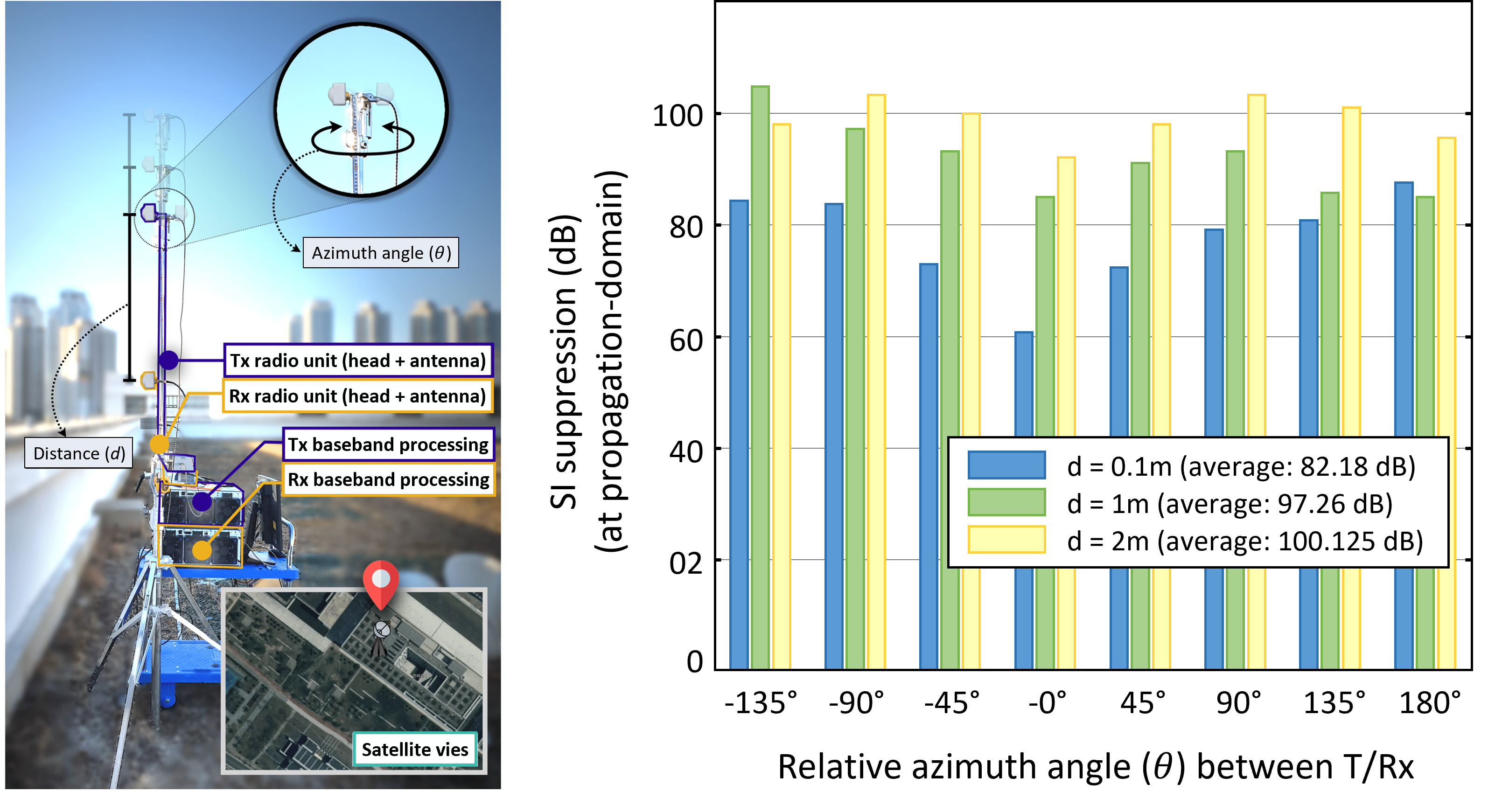
Previous practical observations have shown that a significant part of the total suppression of SI is due to passive analog SIC in the propagation domain. Building on that practical evidence, researchers implemented a hardware prototype for an in-band FD-based IAB system at GHz in [130, 131, 132], and measured the propagation-domain SIC with an MHz bandwidth. This bandwidth is twice the maximum channel bandwidth of the mmWave band in 5G NR. The prototype was developed using the LabVIEW™ system design software and a PXIe software-defined radio platform based on a field-programmable-gate-array (FPGA). The measurement campaign was carried out on the rooftop of a 4-floor building, as shown in the left subfigure of Fig. 13.
The goal of the prototype was to replicate an FD IAB node in a suburban DL setting, where the DU and MT were positioned at a certain distance apart and had different orientations relative to one another. The RX beneath the TX represented the MT of an IAB node, while the TX acted as the DU. The SI in this scenario was the signal on the access link that was not intended for the MT to receive. Nevertheless, we established a synchronized communication link between the DU and MT to measure the SI as the received signal strength. While the experimentation setup provided a useful reference for evaluating the SI suppression performance of IAB by simulating an IAB-node and its environment, improvements in the equipment’s form factor and the surrounding reflectors have yet to be made. These enhancements would lead to a more refined and stable SI mitigation performance. In the designed prototype, both the TX and RX were equipped with a single antenna and a corresponding RF chain. To generate a sharp analog beam at the RX RF front-end, advanced lens antennas with a gain of dBi and an approximate 3 dB beamwidth of 13.4∘ were used. At the TX end, an external power amplifier (PA) with 35 dB gain and a compression point of dBm P1dB was employed.
The measured SI suppression via propagation-domain passive analog SIC in dB as a function of the relative azimuth angle between the TX and RX antennas is illustrated in Fig. 13(c) for various antenna separation distances . The results show that the average suppression for , , and meters were , , and dB, respectively. These values were influenced by the antenna directionality and path loss. This demonstrates that FD-based IAB systems operating at the mmWave frequency band can effectively achieve a significant amount of SI suppression, particularly when compared to the results obtained at the GHz band, as reported in [133, 126, 134]. The aforementioned study demonstrated a SI suppression of dB for a separation distance of meters, utilizing absorbing shielding and cross-polarized antennas. In contrast, the GHz experiment showed an SI suppression of dB for a separation distance of meters, highlighting the importance of using directional antennas [135] (without absorbing shielding) that offer a sharp radiation pattern and high path loss.
III-D Full-Duplex in 5G-Advanced Systems
Opportunity: 5G networks are primarily designed to operate in TDD mode, which offers flexibility in resource allocation and can be deployed in unpaired spectrum bands. Since DL traffic load is often much higher than the UL traffic load, typical TDD schedules assign more time slots to the former, for example, or DL/UL pattern. While this asymmetry is favorable to meet the UL/DL capacity demands, it may compromise the UL performance in terms of latency, which may not be acceptable for applications requiring ultra-reliable low-latency communication (URLLC) links [136]. Therefore, for FD, there is an opportunity to ensure the required flexibility in terms of DL/UL traffic demands, while meeting latency requirements.
State-of-the-art: Recognizing that in multicell systems, different cells may benefit from differing DL/UL patterns, modern cellular networks support dynamic TDD, which allows to dynamically configure of the DL/UL patterns. Although dynamic TDD is attractive, since it can adjust the duplexing pattern to the prevailing traffic load conditions in different cells, it suffers from cross-link interference (CLI) [137, 138]. Due to CLI, which may severely degrade the UL performance due to BS-to-BS interference, dynamic TDD has so far not been successful in practice. However, as effective CLI mitigation schemes emerge, dynamic TDD systems may gain greater adoption in the future [139, 140, 141].
Therefore, meeting the throughput, capacity, reliability, and latency requirements motivates the adoption of FD schemes in evolving 5G systems, since they allow to simultaneously serve UL and DL traffic irrespective of the traffic pattern and without imposing duplexing delay on the UL traffic. However, due to the formidable hardware challenges of implementing high-power FD radios in a cost-efficient fashion, the research and engineering communities have recently proposed the adoption of cross-division duplex (XDD) or subband FD, as an intermediary step from dynamic TDD systems towards true FD communications [142, 139].
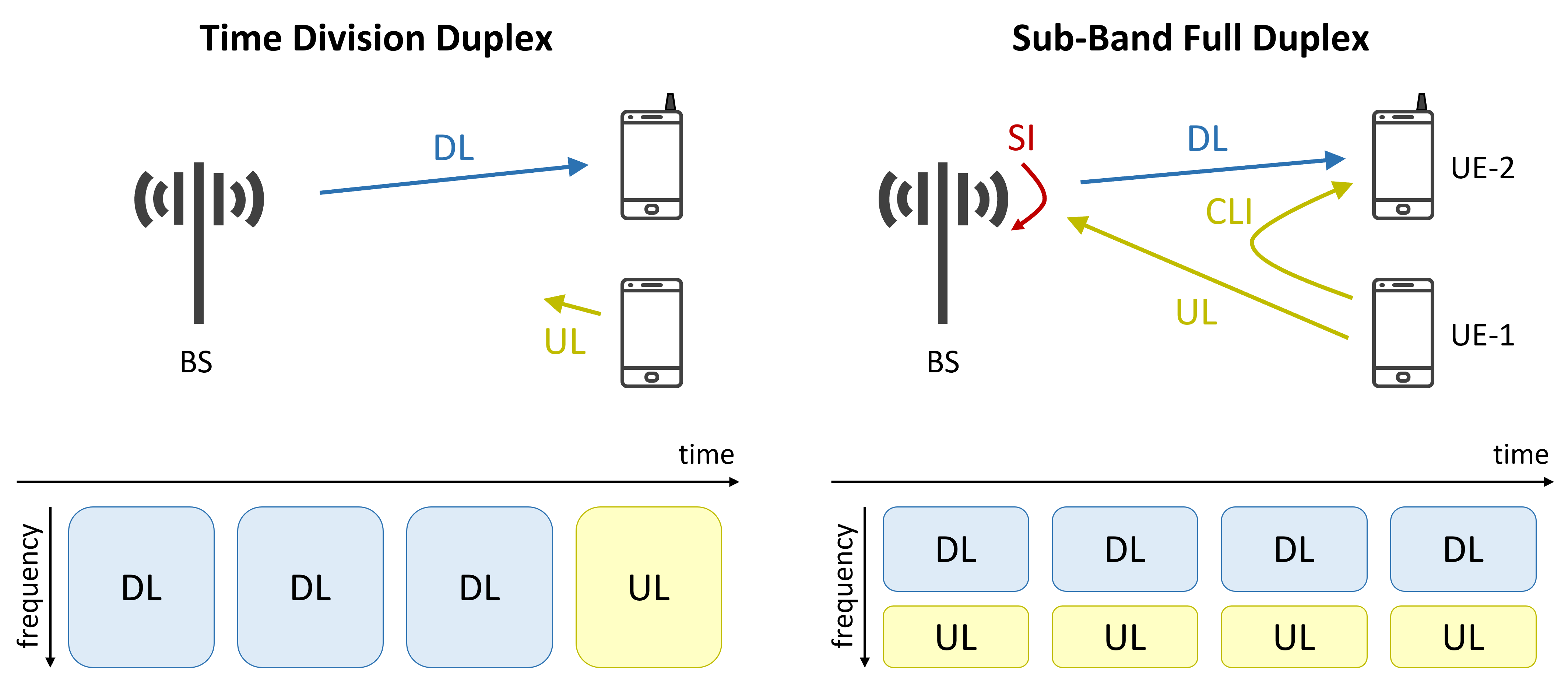
In subband FD, each subband within the TDD carrier implements a specific DL/UL ratio, enabling the cellular BS to operate UL and DL on the same carrier but on different frequency resources within the subband, see Fig. 14 [143]. Notice in Fig. 14 that even though separate chunks of the frequency band are allocated to DL and UL, the BS simultaneously schedules UL data from UE-1 and DL data to UE-2, and thereby implements a (virtual) 3-node FD schedule [144].
Challenges: As discussed, with XDD, two separate TDD schedules operate in adjacent frequency chunks, which gives rise to two problems.
The first problem (crosstalk) is caused by the – typically high-power – DL TX signals operating in close frequency channels to the those used by the UL RX channels, which may saturate the LNA in the receiver chains [143]. The second problem is due to the adjacent channel leakage (ACL) power injected by the TX signals into the UL channels, which may desensitize (block) the receiver amplifier [145]. For cellular BSs employing advanced antenna systems, these problems can be to some extent mitigated by smart antenna assignments (referred to as smart antenna splitting) that assign some antenna elements to either DL or UL traffic, while the remaining antenna elements may act as integrated DL/UL antennas [144]. However, even with careful antenna splitting and antenna isolation techniques, additional isolation enhancements are necessary to reach the at least 100 dB of total isolation of the TX and RX signals. We list some promising techniques that are applicable in advanced antenna and massive MIMO systems:
III-D1 Beam Nulling
Multi-antenna algorithms aim to ensure high signal-to-interference-plus-noise ratio (SINR) at the intended UE devices using beamforming, while creating minimum interference to other UEs by creating nulls in the non-intended directions. In a massive MIMO radio units that support subband or true FD links, additional isolation between the TX and RX antennas may be achieved by creating nulls on the transmit side towards the co-located RX antennas [67, 66, 144]. Such spatial domain interference suppression using beamforming and beam nulling algorithms may degrade the performance of the beamforming algorithm towards the intended UE in terms of the achieved SINR, since some degrees-of-freedom are used to form nulls towards the co-located RX antennas [143].
III-D2 Digital Cancellation and Linearization
As mentioned, subband FD requires to mitigate the impacts of both crosstalk and ACL, while true FD requires to minimize the SI. In both cases, digital cancellation can increase the TX/RX isolation. For digital cancellation, a sufficient ADC/DAC dynamic range and resolution are required to capture both the SI and the desired signals, with enough resolution to cancel the injected TX signal into the RX baseband [146]. In practice, the achievable digital cancellation is affected by hardware impairments and limitations, including nonlinearities, limited dynamic range and resolution of the ADC/DAC circuits, phase noise and multipath environmental reflections.
III-D3 RF Cancellation
RF cancellation creates an intentional and controllable leakage path between the TX and RX chains to provide cancellation at the analog stage of the receiver. It typically provides much higher dynamic range path compared to digital cancellation, making it suitable for minimizing ACL. However, the main challenge of RF cancellation is to manage the associated hardware complexity due to the large number of TX and RX antennas [84, 143].
Similarly to the challenges faced by dynamic TDD systems, a major challenge for introducing FD technology in evolving 5G systems is the intra-cell and inter-cell CLI [139, 147]. As pointed out in [139], dynamic TDD as well as FD cellular networks suffer from two kinds of interference, which are not present in static TDD and FDD systems. The BS-to-BS interference is caused by a transmitting BS to surrounding neighbour BSs that are currently receiving due to operating either in FD or dynamic TDD mode [148, 149]. The UE-to-UE interference is caused by a transmitting UE – either in a dynamic TDD UL slot or as part of an FD schedule – to a receiving UE either in a neighboring dynamic TDD cell or in the same FD cell [150]. These types of interference sources are referred to as intracell or intercell CLI [147]. In practice, the BS-to-BS adjacent-channel CLI, that is, CLI caused by a DL transmission of a BS in a frequency channel to an UL reception of a neighbouring BS in an adjacent frequency channel also needs to be taken into account. This type of CLI includes the adjacent-channel CLI between BSs in the same and different sectors of the same or closely located sites. Finally, adjacent-channel CLI also causes UE-to-UE interference, since an UL transmission of a UE may leak into the DL reception of a DL UE operating in an adjacent frequency channel. To harvest the benefits of FD systems, these additional interference sources need to be mitigated.
As shown in [139, 147, 148], for FD networks to become feasible in multicell cellular networks, the SI, CLI, as well as the conventional intercell interference, must be properly mitigated, which is a difficult requirement in macro networks employing high-power BSs.
Since combating CLI is vital in both dynamic TDD as well as in FD multicell systems, recent research and standardization efforts proposed practical solutions to mitigate CLI [151, 152, 153, 154, 155, 139]. Specifically, a CLI mitigation scheme utilizing a massive number of antennas and ZF, termed BSint was proposed in [139]. This technique utilizes channel state information between neighbor BSs and additional information exchange among BSs through the standardized X2 interface. Building on these pieces of information, transmitting BSs are able to beamform away from neighbors, while using some of their spatial-degrees-of freedom to suppress interference that leaks into the useful signal. Using the BSint technique, BSs can accurately cancel the BS-to-BS interference by using some of their spatial-degrees-of freedom to combat CLI rather than scheduling multiple UEs in the spatial domain [139]. It is important to notice that this scheme is applicable in both dynamic TDD and FD systems.
III-E Low-Latency Networking
Opportunity: Low-latency and highly reliable communications are increasingly important in private and public wireless networks that are deployed to provide mission critical and highly monetizable services, such as factory automation, advanced driver assistance, telemedicine, autonomous train control services and online gaming [156]. Accordingly, one of the goals of 5G NR is to achieve a consistent latency of 1 ms while 6G will further unlock services that demand extremely low latency with additional requirements such as improved spectral and energy efficiency, security and low age-of-information. Moreover, to enhance coverage and capacity, wireless backhauling and multi-hop relaying are emerging as natural components of contemporary and future wireless networks [157, 158, 159, 160]. Cooperative schemes are also attractive for enhancing the coverage and capacity of random access Medium Access Control (MAC) protocols [161]. However, cooperative schemes employing relaying nodes [162, 163, 164, 165, 166, 167] in both scheduled and random access MAC protocols may increase the end-to-end latency due to the need for processing at the relaying node. It has been observed in several recent works that FD-capable relaying nodes may reduce the latency compared with their HD counterparts.
State-of-the-art: Several academic and standardization contributions proposed FD transmission schemes that reduce the end-to-end delay, while maintaining high spectrum utilization and simplifying the MAC design [168, 25, 169, 170, 171, 172, 158, 173, 161]. As previously discussed, 3GPP proposed cost-effective dense deployments of wireless backhauling using IAB nodes to enhance coverage and capacity with rather limited capital expenditures [157], as illustrated in Fig. 11. In fact, FD-based IAB nodes can significantly reduce the delay of packet delivery in multi-hop deployments compared with HD store-and-forward relay nodes [25, 171].
Challenges: As showcased via simulations in [168, 169, 170], FD relays experience interference problems that can limit the relaying gains in the achievable rate. In addition, the FD mode of operation imposes higher processing power at the IAB node, since it has to process twice the number of packets per unit of time due to STAR. An additional challenge for multi-antenna FD IAB nodes is to manage the trade-off between suppressing SI caused by the TX panel to the RX antenna elements and the dynamic beamforming towards the intended RX node, such as the served UE device in the DL direction [158].
As new use cases emerge, future network operations are set to take advantage of innovations made in the areas of computation, storage, and communications to improve user experience [174, 175]. Additionally, features, such as wider bandwidth channels (e.g. in mmWave and sub-THz frequency bands) and strict quality-of-service requirements of applications, continue to demand reduced latency as well as distributed resources for computation and storage. Multi-Access edge computing (MEC) has a significant role in 5G NR, and is expected to do the same in 5G-Advanced and 6G networks, in terms of making use of cloud networking infrastructure to offload some of the user computational tasks to edge servers. However, as the number of UEs getting connected using limited spectrum resources and data generated increases, it becomes challenging for MEC to guarantee low latency. Moreover, today’s MEC architectures are largely ineffective to cater emerging high-throughput and low-latency demands originating from applications such as mixed and extended reality, aiming to combine physical and virtual worlds with haptic interactions. Such applications are expected to gain from FD, involving offloading and downloading made possible due to simultaneous UL and DL transmissions thus significantly reducing the associated latency.
Connected and autonomous driving of the future is another example in which vehicle-to-vehicle communication would benefit from the low-latency capability of FD radios. In those scenarios, the FD mode of operation would enable communication among vehicles through simultaneous sensing and transmission, and without relying on cellular coverage, at low latency to ensure traffic safety [176]. It is also argued in [177] that transceivers capable of FD would merge well with vehicular onboard units without causing power and processing issues. In addition, 5G-Advanced and beyond systems are expected to seamlessly integrate terrestrial, underwater, and air networks to deliver ubiquitous coverage and connect remote areas of the world. In this regard, “connectivity from the sky” is an innovative trend that would connect aerial vehicles such as drones, low- and high-altitude platforms, and satellites with terrestrial segments, bringing new communication opportunities and services. These aerial networks are characterized by frequently varying topologies and very long transmission distances, causing severe communication delays and, in certain cases, outages. To this end, FD radios promise to reduce the involved high latency and improve the network throughput [178, 179]. However, under the FD operation, long-distance satellite communications introduce a power imbalance between the TX and RX signals, rendering SIC a significant challenge.
III-F Interplay with Reconfigurable Intelligent Surfaces (RISs)
Opportunity: A RIS is a two-dimensional metasurface comprising metamaterials, whose responses on impinging electromagnetic signals can be programmed to offer several desired functionalities, like signal scattering, generalized reflection, and absorption [180, 181]. The RIS, commonly discrete, unit elements are usually implemented with basic and ultra-low-power integrated electronic circuits, which are orchestrated in real-time by a dedicated controller. This controller is usually a simple printed circuit board that manages the metasurface’s reconfiguration and is responsible for its interface with the rest of the wireless network [182]. It is envisioned that a RIS can be used to shape the wireless environment for smart and sustainable connectivity [183, 184]. Note that, up to date, wireless environments are not programmable, in the sense that, the propagation of electromagnetic signals is determined by the geometry of the wireless channel, which serves as an uncontrollable factor in a given deployment scenario.
The operation of a RIS closely mimics an amplify-and-forward FD relay [180, 185]. Information-bearing electromagnetic fields are impinging upon an almost passive RIS and get reflected with programmable phase shifts in order to reach the desired end-user location with minimal SI. In such metasurfaces, signal amplification is not feasible, however, there are lately appearing various hardware architectures of RISs with active elements [186], enabling signal reception and sensing at the RIS side [187, 188, 189], as well as reflection amplification [190]. The former category of architectures facilitates the RIS reconfiguration/optimization with reduced overhead, while the latter confronts the inevitable dual path loss effect due to the dual-hop signal propagation. However, in general, a RIS is not expected to be as costly, power-hungry, and computation-capable device as an amplify-and-forward relay, hence, it is envisioned to consist of hundreds of metamaterials. In this way, the RIS technology can become competitive with the relay and/or smart repeater deployments. Very recently, relay-aided RIS deployments have been proposed to exploit the advantages of both propagation extension technologies in order to offer increased network coverage [191].
It is already well known that simultaneously operated and overlapping channels in frequency, resulting from the FD operation, can escalate both the inter- and intra-cell interference in cellular networks [148, 169, 170, 149]. In certain cellular applications, FD BSs and RIS can be deployed in combination to improve the overall system performance. In such deployments, the RISs can help to either enhance the received signals or to control interference at the UEs. To this end, properly designed reflective beams to a particular direction through RIS phase optimization [192] would be an effective solution to lower the number of UEs affected by interfering signals.
State-of-the-art: Optimizing the RIS placement and orientation has been shown to deliver higher gains [193], while switching on/off the RIS is effective to combat blockage-induced effects with high energy efficiency. Moreover, in some applications, such as wireless power transfer, sensor-like devices can harvest energy not only from power beacons but also from reflected signals by the RISs [194]. Leveraging the high-aperture efficiency offered by metasurfaces with fine-grained adjustable phase profiles, passive beamforming gains can be achieved to further deal with the path loss-induced performance degradation![195], and harvesting a significant amount of energy to supplement the energy requirements of wireless devices stand out as a near-term possibility. The combination of FD nodes and RISs can also be used to deliver physical-layer security solutions in emerging networks [196]. Such security techniques are well suited to enhance the security of Internet-of-Things devices that incorporate sensors [197], since such devices are unable to deploy sophisticated security countermeasures. As an example, an RIS can be used to reflect jamming signals generated from FD transceivers, and collectively, such transmissions can enhance the system’s secrecy rate [198].
Potential deployment scenarios combining the FD and RIS technologies are illustrated in Fig. 15. The deployment of an RIS to cover the dead zones of cellular systems, enabling multi-user two-way FD communications, is depicted in Fig. 15(a). The benefits of FD relays and RISs can also be merged to deliver extended coverage and flexible deployment as illustrated in Fig. 15(b), where the orientation and placement of the metasurfaces, as well as the number of multiple signal propagation hops, can be optimized to provide large received SNR within the cell coverage areas. Another example is shown in Fig. 15(c) where an FD BS serves both UL and DL users with the aid of an RIS. The metasurface can dynamically adjust its reflection coefficients to boost the received signal power at the DL receivers. This, in turn, helps to reduce transmit powers at the BS and UL users, rendering the network design spectrally and energy efficient.
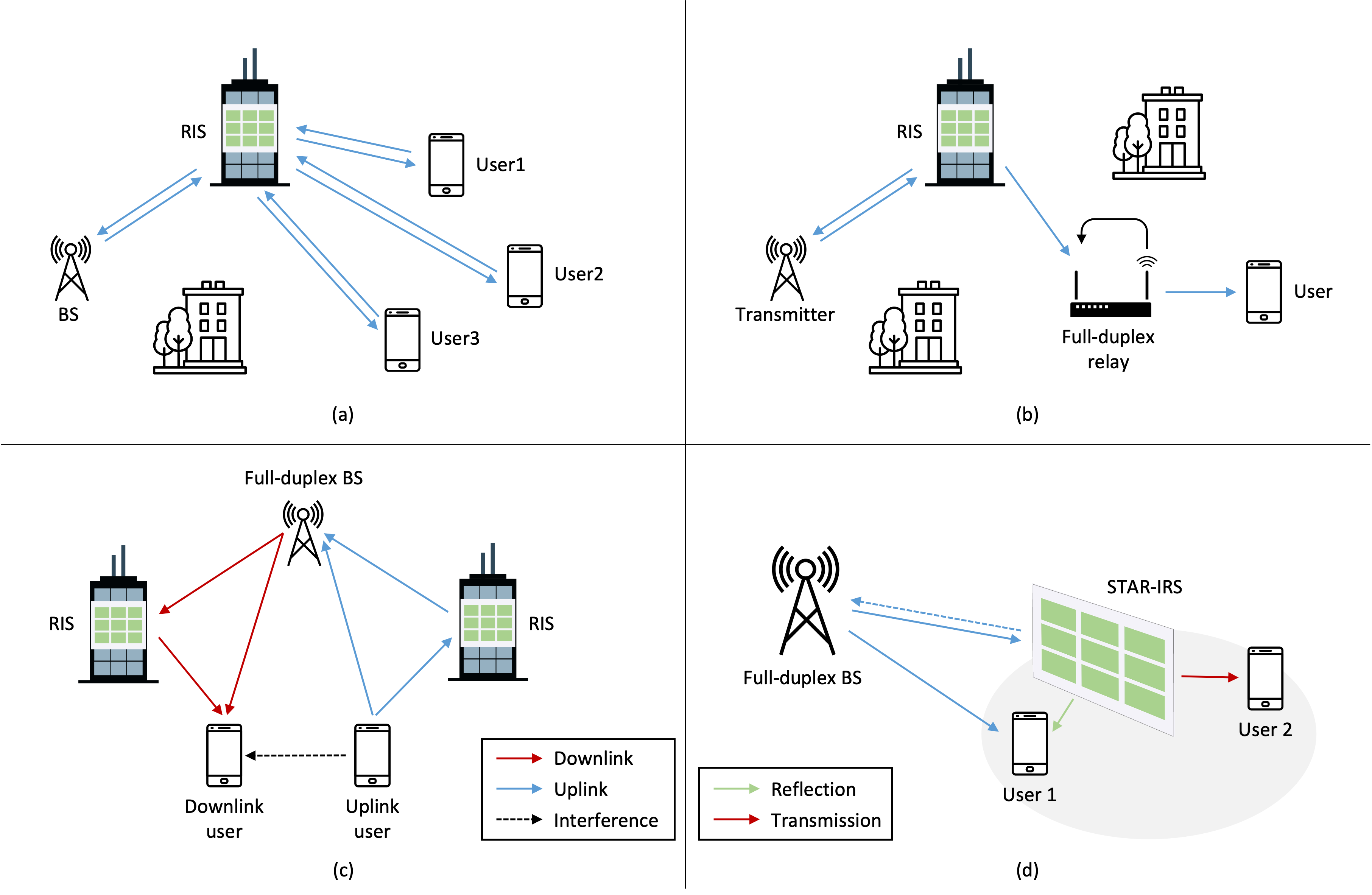
In fact, several late works have investigated the combination of FD transceivers with RISs for two-way communications [199], UL/DL transmission [200], and relaying [191, 201]. The findings of those papers revealed the benefits of using FD communications over HD counterparts in the presence of RISs, in terms of sum-rate maximization and transmit power minimization [202]. Interestingly, to perform SIC, an RIS can be utilized to form a suitable phase-reversed cancellation signal in the analog domain. This novel concept was introduced in [203] in which a greedy heuristic algorithm to converge to a locally optimal RIS phase profile was developed. The -element RIS prototype designed in [203] has been shown to be capable of canceling the leaked signal by dB, achieving a total of dB SI suppression. Clearly, RIS-aided SIC opens up new possibilities for reduced cost transceiver design, potentially allowing conventional transceivers to be operated in the FD mode. However, for the latter framework to be applied with 5G mmWave signals, experimental work to design new RIS-assisted wideband SIC techniques are required. Very recently in [204], an RIS was deployed in the near-field region of an FD MIMO node to enable joint communications and sensing. In particular, the RIS phase configuration was jointly optimized with the MIMO digital beamformers to enable this simultaneous dual functionality, while efficiently handling SI. Near-field ISAC, but in sub-THz frequencies, was also lately investigated in [205] considering a novel FD architecture incorporating metasurface-based holographic MIMO transceivers [206].
In the existing RIS-empowered wireless commnunication systems, the TX and RX have to be on the same side, while this restriction can be removed with the use of the simultaneous transmitting and reflecting RIS (STAR-RIS) concept [207, 208]. Such hybrid metasurfaces are capable of reflecting and transmitting the incident electromagnetic waves into both of their sides. This allows full coverage since UL/DL users located in front and behind of the STAR-RIS can be served, enabling various applications (e.g., simultaneous indoor and outdoor 3D localization [209]). In addition, the transmission and reflection coefficients of the STAR-RIS unit elements can be configured according to a energy splitting, mode switching, and time switching protocols. Such flexible operation enables to optimize diverse design objectives in FD wireless systems, e.g., the sum-rate maximization when users are concurrently operating in the UL and DL directions [210, 211]. As recently shown in [210], all STAR-RIS protocols outperform HD transmissions and those based on the conventional RIS operation. It was also found that, as the number of the STAR-RIS unit elements increases, the average rates of the energy splitting and mode switching protocols increase, however with diminishing returns. The mode switching protocol and that based on the conventional RIS exhibited similar performance for small metasurface elements. Those observations collectively revealed the importance of intelligently selecting the number of STAR-RIS elements and optimizing the amplitudes of reflection and transmission coefficients to improve the system performance.
Challenges: Research on the efficient combination of FD-capable nodes with the RIS technology is still not mature. Acquisition of accurate channel information is a key challenge for active and passive beamforming, since large training overhead and channel estimation errors can limit the desired signal power at users in practice. This inspires the need to develop novel reflective coefficient configuring techniques with low complexity and low power consumption. Although progress has been made in this direction, based, e.g., on approaches such as random phase rotations [212], deep reinforcement learning [213], and parallel factor decomposition [214], the joint consideration with the FD technology is still absent. Hence, joint FD transceiver and hybrid active/passive RIS designs and respective algorithmic optimizations are notable research directions. Coordination of multiple RISs to control the interfering signals and enable their energy-efficient green operation serves as another key challenge in multi-cell mixed HD and FD networks. There are some promising directions to follow in this research direction, such as advanced network designs based on distributed machine learning, optimization and intelligent resource allocation, as well as research on novel signaling schemes and intelligent network orchestration. However, their effectiveness needs to be showcased through dedicated research.
III-G Empowering Non-Terrestrial Networks (NTNs)
Opportunity: 6G’s vision represents a major departure from past wireless standards, which concentrated on providing coverage on the ground. Instead, the overarching goal is to integrate both ground and air by leveraging drones and high-altitude platforms (HAPs) to achieve worldwide connectivity [215, 216]. Additionally, due to advancements in materials development, inexpensive manufacturing, and satellite launches, NTNs in the form of mega constellation cube satellites are anticipated to be a component of 6G. This new wave of innovation is highlighted in recent publications in 2022 [217].
In comparison to geostationary earth orbit satellites, which orbit at a distance of 35,800 km from Earth, drones, HAPs, and nanosatellites operate at a much lower altitude. Unmanned aerial vehicles (UAVs) typically fly at an altitude of a few hundred meters above the ground, while HAPs can be positioned in the stratosphere at an altitude of 20 km. Low-Earth-orbit (LEO) satellites, on the other hand, orbit at an altitude ranging between 200 and 2000 km [218]. These lower orbits cause LEO satellites to be “non-stationary” in relation to the ground. Therefore, a constellation of LEO satellites is necessary to ensure service continuity. However, the shorter transmission distances of drones, HAPs, and LEO satellites result in less propagation loss, higher signal strength attenuation, and a lower transmission delay. These appealing features have prompted 3GPP to initiate study items through Rel. 14 to Rel. 20, identifying architectures, potential issues, and use cases such as roaming, backhauling, broadcast/multicast, and IoT, with the goal of integrating NTNs into modern cellular systems and beyond [217, 219].
The above-mentioned features bring forth fresh possibilities for FD operation in aerial networks of 6G. One such opportunity is the relaxation of the power imbalance between the transmitting and receiving signals, thereby reducing the burden of self-interference (SI) that can lead to performance deterioration due to shorter transmission distances. Furthermore, advancements in powerful on-board capabilities such as processors, high-gain antennas, RF hardware, and low complexity signal processing algorithms are making significant progress. This progress is expected to facilitate the implementation of feasible SI cancellation schemes that can leverage these developments for FD implementation.
One potential application of upcoming aerial networks is to enable Internet of Things (IoT) services in remote and unconnected locations, such as polar regions, oceans, and even space. Since many IoT applications are sensitive to latency, FD operation can help minimize delays in end-to-end data delivery. As NTNs continue to evolve, new use cases requiring higher spectral efficiencies are expected to emerge. These applications would benefit from the increased spectral efficiencies offered by FD. Security is also a crucial consideration for communication in NTNs. For example, drones are increasingly being used in the military for surveillance and localization purposes, making them susceptible to jamming attacks by external parties due to their relatively shorter distances. In response, FD-capable aerial vehicles can perform active jamming while simultaneously receiving information, thereby ensuring improved physical layer security.
State-of-the-art: Several recent studies have investigated the feasibility of using FD mode for communication in UAV and satellite networks, with a focus on performance analysis and optimization. For instance, [220] aimed to achieve 130 dB of SI cancellation for an FD ground-LEO satellite link using expensive components. In [221], the benefits of using FD relaying on-board DVB-S2 satellite networks were demonstrated, including more efficient use of satellite spectrum. In [222], the use of an FD UAV as an aerial base station for small cell wireless communication was studied, and system performance was optimized by optimizing the UAV trajectory, DL/UL user scheduling, and UL user transmit power to maximize the system’s UL and DL sum rate. In [223], power allocation, user pairing, and subchannel assignment were optimized for a UL/DL communication system that used a UAV as a relay, and the authors demonstrated that a proposed non-orthogonal access method could provide better spectral and energy efficiencies than the orthogonal access method. In [224], multiple UAVs simultaneously reused all available DL and UL channels, while using isolated DL and UL channels to avoid SI, but directional antennas and flight control of the UAVs were used to eliminate co-channel interference. In [225], the outage probability of a satellite-ground network utilizing FD relays and relay selection was studied in the presence of interference, while [226] presented a two-tier cache-enabled satellite-terrestrial network that used FD transmission to reduce content delivery latency. However, the motion of aerial terminals can introduce significant challenges for FD implementation, including handover and interference control, and the limited onboard energy of aerial vehicles may limit the introduction of FD aerial terminals for certain use cases.
Challenges: The movement of aerial terminals poses considerable obstacles to implementing FD, particularly in terms of handover and interference control. For instance, the flight paths of drones may lead to time-varying interference patterns of varying strengths between air-to-air or air-to-ground signals. Additionally, dynamic and challenging-to-model shadowing conditions in certain scenarios could further complicate how interference affects performance. Thus, integrating air or space segments with terrestrial networks would require meticulous planning. Furthermore, for certain use cases, the limited on-board energy available could significantly constrain the adoption of FD aerial terminals, unless lightweight and cost-effective energy storage technologies are developed in the near future.
IV Future Outlook and Concluding Remarks
Wireless networks are poised for a significant transformation, offering new degrees of design freedom in the form of fresh spectrum, advanced sensing capabilities, and novel use cases. Additionally, learning-based methods will play a pivotal role in this evolution, particularly in 5G-Advanced Rel-18 and beyond, where artificial intelligence and machine learning techniques will enhance the air interface by enabling adaptive waveform design, energy-efficient sustainable operation, and predictive user mobility patterns and behavior. Devices and systems that support FD communication will complement these new design degrees, pushing the limits of throughput and latency. Moreover, learning-based methods hold promise for eliminating the need for hand-tuning and effectively canceling self-interference in the presence of system nonlinearities and challenging wireless propagation conditions. As in-band full-duplex communication gains wider acceptance in standards, it is not only becoming a well-established concept but also an active area of research. This overview highlighted some of the emerging research and usage directions for in-band FD communication, with many new opportunities and challenges remaining, as evidenced by the strong set of papers in this special issue.
References
- [1] Ericsson, “Ericsson Mobility Report,” Nov. 2022 [Online], https://www.ericsson.com/en/reports-and-papers/mobility-report.
- [2] M. Z. Chowdhury, M. Shahjalal, S. Ahmed, and Y. M. Jang, “6G wireless communication systems: Applications, requirements, technologies, challenges, and research directions,” IEEE Open J. Commun. Soc., vol. 1, pp. 957–975, 2020.
- [3] H. Tataria, M. Shafi, A. F. Molisch, M. Dohler, H. Sjöland, and F. Tufvesson, “6G wireless systems: Vision, requirements, challenges, insights, and opportunities,” Proc. IEEE, vol. 109, no. 7, pp. 1166–1199, 2021.
- [4] F. Tariq, M. R. A. Khandaker, K.-K. Wong, M. A. Imran, M. Bennis, and M. Debbah, “A speculative study on 6G,” IEEE Wireless Commun., vol. 27, no. 4, pp. 118–125, 2020.
- [5] W. Chen, X. Li, J. Lee, A. Toskala, S. Sun, C. F. Chiasserini, and L. Liu, “5G-Advanced towards 6G: Past, present, and future,” arXiv preprint arXiv:2303.07456, 2023.
- [6] G. Fodor, C.-B. Chae, R. Wichman, A. Sabharwal, H. A. Suraweera, R. Rao, and H. Alves, “Guest editorial: Full duplex communications theory, standardization, and practice,” IEEE Wireless Commun. Mag., vol. 28, no. 1, pp. 10–11, 2021.
- [7] J. Kwak, H. B. Yilmaz, N. Farsad, C.-B. Chae, and A. Goldsmith, “Two-way molecular communications,” IEEE Trans. Commun., vol. 6, no. 68, pp. 3550–3563, June 2020.
- [8] M. Duarte and A. Sabharwal, “Full-duplex wireless communications using off-the-shelf radios: Feasibility and first results,” in Proc. Asilomar Conference on Signals, Systems and Computers, 2010, pp. 1558–1562.
- [9] J. I. Choi, M. Jain, K. Srinivasan, P. Levis, and S. Katti, “Achieving single channel, full duplex wireless communication,” in Proc. Annual International Conference on Mobile Computing and Networking (MobiCom), 2010, pp. 1–12.
- [10] D. W. Bliss, P. A. Parker, and A. R. Margetts, “Simultaneous transmission and reception for improved wireless network performance,” in Proc. IEEE/SP Workshop on Statistical Signal Processing, 2007, pp. 478–482.
- [11] A. K. Khandani, “Methods for spatial multiplexing of wireless two-way channels,” in US Patent US7817641, Oct. 2010.
- [12] E. Everett, M. Duarte, C. Dick, and A. Sabharwal, “Empowering full-duplex wireless communication by exploiting directional diversity,” in Proc. Asilomar Conference on Signals, Systems and Computers (ASILOMAR), 2011, pp. 2002–2006.
- [13] M. Jain, J. I. Choi, T. Kim, D. Bharadia, S. Seth, K. Srinivasan, P. Levis, S. Katti, and P. Sinha, “Practical, real-time, full duplex wireless,” in Proc. Annual International Conference on Mobile Computing and Networking (MobiCom), 2011, pp. 301–312.
- [14] A. K. Khandani, “Shaping the future of wireless: Two-way connectivity,” http://www.nortel-institute.uwaterloo.ca/content/Shaping Future of Wireless Two-way Connectivity 18ne2012.pdf, June 2012.
- [15] M. Duarte, C. Dick, and A. Sabharwal, “Experiment-driven characterization of full-duplex wireless systems,” IEEE Trans. Wireless Commun., vol. 11, no. 12, pp. 4296–4307, 2012.
- [16] E. Aryafar, M. A. Khojastepour, K. Sundaresan, S. Rangarajan, and M. Chiang, “MIDU: Enabling MIMO full duplex,” in Proc. ACM Mobile Comp. and Net. (MobiCOM), Aug. 2012, pp. 257–268.
- [17] M. Duarte, A. Sabharwal, V. Aggarwal, R. Jana, K. K. Ramakrishnan, C. W. Rice, and N. K. Shankaranarayanan, “Design and characterization of a full-duplex multiantenna system for WiFi networks,” IEEE Trans. Veh. Technol., vol. 63, no. 3, pp. 1160–1177, 2014.
- [18] D. Righini and A. M. Tonello, “MIMO in-band-full-duplex PLC: Design, analysis and first hardware realization of the analog self-interference cancellation stage,” IEEE Open J. Commun. Soc., vol. 2, pp. 1344–1357, 2021.
- [19] T. Riihonen, S. Werner, and R. Wichman, “Hybrid full-duplex/half-duplex relaying with transmit power adaptation,” IEEE Trans. Wireless Commun., vol. 10, no. 9, pp. 3074–3085, 2011.
- [20] ——, “Mitigation of loopback self-interference in full-duplex MIMO relays,” IEEE Trans. Signal Process., vol. 59, no. 12, pp. 5983–5993, 2011.
- [21] I. Krikidis, H. A. Suraweera, S. Yang, and K. Berberidis, “Full-duplex relaying over block fading channel: A diversity perspective,” IEEE Trans. Wireless Commun., vol. 11, no. 12, pp. 4524–4535, 2012.
- [22] S. Hong, J. Brand, J. I. Choi, M. Jain, J. Mehlman, S. Katti, and P. Levis, “Applications of self-interference cancellation in 5G and beyond,” IEEE Commun. Mag., vol. 52, no. 2, pp. 114–121, 2014.
- [23] A. Sabharwal, P. Schniter, D. Guo, D. W. Bliss, S. Rangarajan, and R. Wichman, “In-band full-duplex wireless: Challenges and opportunities,” IEEE J. Sel. Areas Commun., vol. 32, no. 9, pp. 1637–1652, Jun. 2014.
- [24] M. Heino, D. Korpi, T. Huusari, E. Antonio-Rodriguez, S. Venkatasubramanian, T. Riihonen, L. Anttila, C. Icheln, K. Haneda, R. Wichman, and M. Valkama, “Recent advances in antenna design and interference cancellation algorithms for in-band full duplex relays,” IEEE Commun. Mag., vol. 53, no. 5, pp. 91–101, 2015.
- [25] Z. Zhang, K. Long, A. V. Vasilakos, and L. Hanzo, “Full-duplex wireless communications: Challenges, solutions, and future research directions,” Proc. IEEE, vol. 104, no. 7, pp. 1369–1409, 2016.
- [26] N. V. Shende, O. Gürbüz, and E. Erkip, “Half-duplex or full-duplex communications: Degrees of freedom analysis under self-interference,” IEEE Trans. Wireless Commun., vol. 17, no. 2, pp. 1081–1093, 2018.
- [27] M. Mohammadi, X. Shi, B. K. Chalise, Z. Ding, H. A. Suraweera, C. Zhong, and J. S. Thompson, “Full-duplex non-orthogonal multiple access for next generation wireless systems,” IEEE Commun. Mag., vol. 57, no. 5, pp. 110–116, 2019.
- [28] K. E. Kolodziej, B. T. Perry, and J. S. Herd, “In-band full-duplex technology: Techniques and systems survey,” IEEE Trans. Microw. Theory Tech., vol. 67, no. 7, pp. 3025–3041, 2019.
- [29] S. Vaibhav, M. Susnata, G. Akshay, S. Milind, P. Jeyanandh, and K. Swarun, “Millimeter-wave full duplex radios,” in Proc. 26th Annual International Conference on Mobile Computing and Networking (MobiCom ’20), 2020, pp. 1–14.
- [30] I. P. Roberts and H. A. Suraweera, “Full-duplex transceivers for next-generation wireless communication systems,” arXiv preprint arXiv:2210.08094, 2022.
- [31] L. Song, R. Wichman, Y. Li, and Z. Han, Full-Duplex Communications and Networks. Cambridge University Press, 2017.
- [32] H. Alves, T. Riihonen, and H. A. Suraweera, Full-Duplex Communications for Future Wireless Networks. Springer, 2020.
- [33] K. Kolodziej, In-Band Full-Duplex Wireless Systems Handbook. Artech House, 2021.
- [34] B. Berscheid and C. Howlett, “Full duplex DOCSIS: Opportunities and challenges,” IEEE Commun. Mag., vol. 57, no. 8, pp. 28–33, 2019.
- [35] L. Anttila, D. Korpi, V. Syrjälä, and M. Valkama, “Cancellation of power amplifier induced nonlinear self-interference in full-duplex transceivers,” in Proc. Asilomar Conference on Signals, Systems and Computers, 2013, pp. 1193–1198.
- [36] A. Sahai, G. Patel, C. Dick, and A. Sabharwal, “On the impact of phase noise on active cancelation in wireless full-duplex,” IEEE Trans. Veh. Technol., vol. 62, no. 9, pp. 4494–4510, Nov. 2013.
- [37] T. Oh, Y.-G. Lim, C.-B. Chae, and Y. Lee, “Dual-polarization slot antenna with high cross-polarization discrimination for indoor small-cell MIMO systems,” IEEE Antennas Wirel. Propag. Lett., vol. 14, no. Feb., pp. 374–377, 2015.
- [38] M. Chung, M. S. Sim, J. Kim, D. K. Kim, and C.-B. Chae, “Prototyping real-time full duplex radios,” IEEE Commun. Mag., vol. 53, no. 9, pp. 56–63, Sep. 2015.
- [39] E. Everett, A. Sahai, and A. Sabharwal, “Passive self-interference suppression for full-duplex infrastructure nodes,” IEEE Trans. Wireless Commun., vol. 13, no. 2, pp. 680–694, Jan. 2014.
- [40] Y. Xing, S. Li, X. Chen, X. Xue, and X. Zheng, “Optical multi-tap rf canceller for in-band full-duplex wireless communication systems,” IEEE Photonics J., vol. 14, no. 5, pp. 1–7, 2022.
- [41] K. E. Kolodziej, A. U. Cookson, and B. T. Perry, “RF canceller tuning acceleration using neural network machine learning for in-band full-duplex systems,” IEEE Open J. Commun. Soc., vol. 2, pp. 1158–1170, 2021.
- [42] T. Huusari, Y.-S. Choi, P. Liikkanen, D. Korpi, S. Talwar, and M. Valkama, “Wideband self-adaptive RF cancellation circuit for full-duplex radio: Operating principle and measurements,” in IEEE Vehicular Technology Conference (VTC Spring), 2015, pp. 1–7.
- [43] S. Maddio, A. Cidronali, A. Palonghi, and G. Manes, “A reconfigurable leakage canceler at 5.8 GHz for DSRC applications,” in Proc. IEEE MTT-S International Microwave Symposium Digest (MTT 2013), June 2013, pp. 1–3.
- [44] S. Khaledian, F. Farzami, B. Smida, and D. Erricolo, “Inherent self-interference cancellation at 900 MHz for in-band full-duplex applications,” in Proc. IEEE Wireless and Microwave Technology Conference (WAMICON 2018), 2018, pp. 1–4.
- [45] ——, “Inherent self-interference cancellation for in-band full-duplex single-antenna systems,” IEEE Trans. Microw. Theory Tech., vol. 66, no. 6, pp. 2842–2850, 2018.
- [46] E. Ahmed and A. M. Eltawil, “All-digital self-interference cancellation technique for full-duplex systems,” IEEE Trans. Wireless Commun., vol. 14, no. 7, pp. 3519–3532, 2015.
- [47] D. Korpi, L. Anttila, V. Syrjälä, and M. Valkama, “Widely linear digital self-interference cancellation in direct-conversion full-duplex transceiver,” IEEE J. Sel. Areas Commun., vol. 32, no. 9, pp. 1674–1687, 2014.
- [48] X. Quan, Y. Liu, S. Shao, C. Huang, and Y. Tang, “Impacts of phase noise on digital self-interference cancellation in full-duplex communications,” IEEE Trans. Signal Process., vol. 65, no. 7, pp. 1881–1893, 2017.
- [49] A. Balatsoukas-Stimming, A. Austin, P. Belanovic, and A. Burg, “Baseband and rf hardware impairments in full-duplex wireless systems: experimental characterisation and suppression,” EURASIP J. Wirel. Commun. Netw., vol. 2015, no. 1, pp. 1–11, 2015.
- [50] M. A. Islam and B. Smida, “A comprehensive self-interference model for single-antenna full-duplex communication systems,” in Proc. IEEE International Conference on Communications (ICC), May 2019, pp. 1–7.
- [51] A. Balatsoukas-Stimming, “Non-linear digital self-interference cancellation for in-band full-duplex radios using neural networks,” in Proc. IEEE SPAWC 2018, Kalamata, Greece, June 2018, pp. 1–5.
- [52] H. Guo, S. Wu, H. Wang, and M. Daneshmand, “Deep learning based self-interference cancellation for in-band full duplex wireless,” in Proc. IEEE Global Commun. Conf. (GLOBECOM), Dec. 2019, pp. 1–6.
- [53] C. Shi, Y. Hao, Y. Liu, and S. Shao, “Digital self-interference cancellation for full duplex wireless communication based on neural networks,” in Proc. Int. Conf. Commun. and Inform. Syst., Wuhan, China, Dec. 2019, pp. 53–57.
- [54] Y. Kurzo, A. Burg, and A. Balatsoukas-Stimming, “Design and implementation of a neural network aided self-interference cancellation scheme for full-duplex radios,” in Proc. Asilomar Conf. Signals, Syst. and Comput., Oct. 2018, pp. 589–593.
- [55] C. Huang, G. C. Alexandropoulos, A. Zappone, C. Yuen, and M. Debbah, “Deep learning for UL/DL channel calibration in generic massive MIMO systems,” in Proc. IEEE Intl. Conf. Commun. (ICC), Dec. 2019, pp. 1–6.
- [56] M. Elsayed, A. A. A. El-Banna, O. A. Dobre, W. Shiu, and P. Wang, “Low complexity neural network structures for self-interference cancellation in full-duplex radio,” IEEE Commun. Lett., vol. 25, no. 1, pp. 181–185, 2021.
- [57] ——, “Hybrid-layers neural network architectures for modeling the self-interference in full-duplex systems,” IEEE Trans. Veh. Technol., vol. 71, no. 6, pp. 6291–6307, 2022.
- [58] D. Korpi, L. Anttila, and M. Valkama, “Nonlinear self-interference cancellation in MIMO full-duplex transceivers under crosstalk,” EURASIP J. Wireless Commun. Netw., no. 24, 2017.
- [59] K. Muranov, M. A. Islam, B. Smida, and N. Devroye, “On deep learning assisted self-interference estimation in a full-duplex relay link,” IEEE Wireless Commun. Lett., vol. 10, no. 12, pp. 2762–2766, 2021.
- [60] D. H. Kong, Y.-S. Kil, and S.-H. Kim, “Neural network aided digital self-interference cancellation for full-duplex communication over time-varying channels,” IEEE Trans. Veh. Technol., vol. 71, no. 6, pp. 6201–6213, 2022.
- [61] G. C. Alexandropoulos, M. A. Islam, and B. Smida, “Full duplex massive MIMO architectures: Recent advances, applications, and future directions,” IEEE Veh. Technol. Mag., vol. 17, no. 4, pp. 83–91, Dec. 2022.
- [62] D. Bharadia and S. Katti, “Full duplex MIMO radios,” in Proc. IEEE USENIX NSDI, Apr. 2014, pp. 359–372.
- [63] A. Sahai, G. Patel, and A. Sabharwal, “Asynchronous full-duplex wireless,” in ”Proc. Int. Conf. on Commun. Systems and Networks”, 2012, pp. 1 – 9.
- [64] K. E. Kolodziej, J. G. McMichael, and B. T. Perry, “Multitap RF canceller for in-band full-duplex wireless communications,” IEEE Trans. Wireless Commun., vol. 15, no. 6, pp. 4321–4334, Jun. 2016.
- [65] E. Everett, C. Shepard, L. Zhong, and A. Sabharwal, “SoftNull: Many-antenna full-duplex wireless via digital beamforming,” IEEE Trans. Wireless Commun., vol. 12, no. 15, pp. 80 770–8092, Dec. 2016.
- [66] N. M. Gowda and A. Sabharwal, “JointNull: Combining partial analog cancellation with transmit beamforming for large-antenna full-duplex wireless systems,” IEEE Trans. Wireless Commun., vol. 17, no. 3, pp. 2094–2108, 2018.
- [67] H. Q. Ngo, H. A. Suraweera, M. Matthaiou, and E. G. Larsson, “Multipair full-duplex relaying with massive arrays and linear processing,” IEEE J. Sel. Areas Commun., vol. 32, no. 9, pp. 1721–1737, 2014.
- [68] S.-M. Kim, Y.-G. Lim, L. Dai, and C.-B. Chae, “Performance analysis of self-interference cancellation in full-duplex massive MIMO systems: Subtraction versus spatial suppression,” IEEE Trans. Wireless Commun., vol. 22, no. 1, pp. 642–657, Jan. 2023.
- [69] H. A. Suraweera, I. Krikidis, G. Zheng, C. Yuen, and P. J. Smith, “Low-complexity end-to-end performance optimization in MIMO full-duplex relay systems,” IEEE Trans. Wireless Commun., vol. 13, no. 2, pp. 913–927, 2014.
- [70] N. Zarifeh, Y. Zantah, Y. Gao, and T. Kaiser, “Full-duplex femto base-station with antenna selection: Experimental validation,” IEEE Access, vol. 7, pp. 108 781–108 794, 2019.
- [71] M. Mohammadi, Z. Mobini, H. A. Suraweera, and Z. Ding, “Antenna selection in full-duplex cooperative NOMA systems,” in Proc. IEEE Intl. Conf. Commun. (ICC), May 2018, pp. 1–6.
- [72] Z. Mobini, M. Mohammadi, T. A. Tsiftsis, Z. Ding, and C. Tellambura, “New antenna selection schemes for full-duplex cooperative MIMO-NOMA systems,” IEEE Trans. Commun., vol. 70, no. 7, pp. 4343–4358, 2022.
- [73] G. C. Alexandropoulos, M. A. Islam, and B. Smida, “Full duplex hybrid A/D beamforming with reduced complexity multi-tap analog cancellation,” in Proc. IEEE SPAWC, May 2020, pp. 1–6.
- [74] I. P. Roberts, A. Chopra, T. Novlan, S. Vishwanath, and J. G. Andrews, “Steer: Beam selection for full-duplex millimeter wave communication systems,” IEEE Trans. Commun., vol. 70, no. 10, pp. 6902–6917, 2022.
- [75] Z. Chen, C. B. Barati, J. Veihl, C. Shepard, and A. Sabharwal, “Lensfd: Using lenses for improved sub-6 ghz massive mimo full-duplex,” IEEE Transactions on Vehicular Technology, 2023.
- [76] M. Mohammadi, H. A. Suraweera, and C. Tellambura, “Uplink/downlink rate analysis and impact of power allocation for full-duplex cloud-RANs,” IEEE Trans. Wireless Commun., vol. 17, no. 9, pp. 5774–5788, 2018.
- [77] R. Sultan, K. G. Seddik, Z. Han, and B. Aazhang, “Joint transmitter-receiver optimization and self-interference suppression in full-duplex MIMO systems,” IEEE Trans. Veh. Technol., vol. 70, no. 7, pp. 6913–6929, 2021.
- [78] G. C. Alexandropoulos and M. Duarte, “Joint design of multi-tap analog cancellation and digital beamforming for reduced complexity full duplex MIMO systems,” in Proc. IEEE Intl. Conf. Commun. (ICC), May 2017.
- [79] M. A. Islam, G. C. Alexandropoulos, and B. Smida, “A unified beamforming and A/D self-interference cancellation design for full duplex MIMO radios,” in Proc. IEEE PIMRC, Sep. 2019.
- [80] H. Iimori, G. Abreu, and G. C. Alexandropoulos, “MIMO beamforming schemes for hybrid SIC FD radios with imperfect hardware and CSI,” IEEE Trans. Wireless Commun., vol. 18, no. 10, pp. 4816–4830, Oct. 2019.
- [81] G. C. Alexandropoulos, “Low complexity full duplex MIMO systems: Analog canceler architectures, beamforming design, and future directions,” ITU J. Future Evolving Technol., vol. 2, no. 2, pp. 1–19, Dec. 2021.
- [82] C.-T. Lin, F.-S. Tseng, and W.-R. Wu, “MMSE transceiver design for full-duplex MIMO relay systems,” IEEE Trans. Veh. Technol., vol. 66, no. 8, pp. 6849–6861, 2017.
- [83] M. A. Islam, G. C. Alexandropoulos, and B. Smida, “Joint analog and digital transceiver design for wideband full duplex MIMO systems,” IEEE Trans. Wireless Commun., early access, 2022.
- [84] M. Duarte and G. C. Alexandropoulos, “Full duplex MIMO digital beamforming with reduced complexity AUXTX analog cancellation,” in Proc. IEEE Intl. Conf. Commun. (ICC), Jun. 2020, pp. 1–6.
- [85] S.-M. Kim, Y.-G. Lim, L. Dai, and C.-B. Chae, “Performance analysis of self-interference cancellation in full-duplex massive MIMO systems: Subtraction versus spatial suppression,” IEEE Trans. Wireless Commun., vol. 22, no. 1, pp. 642–657, 2023.
- [86] N. M. Gowda and A. Sabharwal, “Jointnull: Combining partial analog cancellation with transmit beamforming for large-antenna full-duplex wireless systems,” IEEE Trans. Wireless Commun., vol. 17, no. 3, pp. 2094–2108, Mar. 2018.
- [87] I. P. Roberts, H. B. Jain, and S. Vishwanath, “Equipping millimeter-wave full-duplex with analog self-interference cancellation,” in Proc. IEEE Intl. Conf. Commun. (ICC), Jun. 2020, pp. 1–6.
- [88] Z. Xiao, P. Xia, and X.-G. Xia, “Full-duplex millimeter-wave communication,” IEEE Wireless Commun., vol. 24, no. 6, pp. 136–143, Dec. 2017.
- [89] K. Satyanarayana, M. El-Hajjar, P.-H. Kuo, A. Mourad, and L. Hanzo, “Hybrid beamforming design for full-duplex millimeter wave communication,” IEEE Trans. Veh. Technol., vol. 68, no. 2, pp. 1394–1404, Dec. 2018.
- [90] I. P. Roberts and S. Vishwanath, “Beamforming cancellation design for millimeter-wave full-duplex,” in Proc. IEEE Global Commun. Conf. (GLOBECOM), Dec. 2019, pp. 1–6.
- [91] J. M. B. Da Silva, A. Sabharwal, G. Fodor, and C. Fischione, “1-bit phase shifters for large-antenna full-duplex mmwave communications,” IEEE Trans. Wireless Commun., vol. 19, no. 10, pp. 6916–6931, Jul. 2020.
- [92] Y. Chen, R. K. Mishra, D. Schwartz, and S. Vishwanath, “MIMO full duplex radios with deep learning,” in Proc. 2020 IEEE Intl. Conf. Commun. Workshops (ICC Workshops), 2020, pp. 1–6.
- [93] J. A. Zhang, F. Liu, C. Masouros, R. W. Heath, Z. Feng, L. Zheng, and A. Petropulu, “An overview of signal processing techniques for joint communication and radar sensing,” IEEE J. Sel. Topics Signal Process., vol. 15, no. 6, pp. 1295–1315, 2021.
- [94] F. Liu, Y. Cui, C. Masouros, J. Xu, T. X. Han, Y. C. Eldar, and S. Buzzi, “Integrated sensing and communications: Toward dual-functional wireless networks for 6G and beyond,” IEEE J. Sel. Areas Commun., vol. 40, no. 6, pp. 1728–1767, 2022.
- [95] F. Liu, C. Masouros, A. P. Petropulu, H. Griffiths, and L. Hanzo, “Joint radar and communication design: Applications, state-of-the-art, and the road ahead,” IEEE Trans. Commun., vol. 68, no. 6, pp. 3834–3862, 2020.
- [96] X. Liu, T. Huang, N. Shlezinger, Y. Liu, J. Zhou, and Y. C. Eldar, “Joint transmit beamforming for multiuser MIMO communications and MIMO radar,” IEEE Trans. Signal Process., vol. 68, pp. 3929–3944, 2020.
- [97] “3GPP S1-214242 New SID on study on integrated sensing and communication, 3GPP System Architecture Group SA1,” Nov. 2021.
- [98] A. Behravan, R. Baldemair, S. Parkvall, E. Dahlman, V. Yajnanarayana, H. Björkegren, and D. Shrestha, “Introducing sensing into future wireless communication systems,” in Proc. 2nd IEEE International Symposium on Joint Communications & Sensing (JC&S 2022), Seefeld, Austria, 2022, pp. 1–5.
- [99] C. Wu, B. Wang, O. C. Au, and K. R. Liu, “Wi-fi can do more: Toward ubiquitous wireless sensing,” IEEE Commun. Stand. Mag., vol. 6, no. 2, pp. 42–49, 2022.
- [100] M. Davis, “Key differences between radar and communications systems,” in Proc. Annu. Int. Symp. Adv. Radio Technol., Jul. 2011, Available: https://www.its.bldrdoc.gov/media/31075/DavisRadar_vs_comms.pdf.
- [101] C. B. Barneto, E. Rastorgueva-Foi, M. F. Keskin, T. Riihonen, M. Turunen, J. Talvitie, H. Wymeersch, and M. Valkama, “Millimeter-wave mobile sensing and environment mapping: Models, algorithms and validation,” IEEE Trans. Veh. Technol., vol. 71, no. 4, pp. 3900–3916, 2022.
- [102] N. Mehrotra and A. Sabharwal, “When does multipath improve imaging resolution?” IEEE Journal on Selected Areas in Information Theory, vol. 3, no. 1, pp. 135 – 146, March 2022.
- [103] F. Liu, Y. Cui, C. Masouros, J. Xu, T. X. Han, Y. C. Eldar, and S. Buzzi, “Integrated sensing and communications: Towards dual-functional wireless networks for 6G and beyond,” IEEE J. Sel. Areas Commun., vol. 40, no. 6, pp. 1728–1767, 2022.
- [104] S. Prabhakar Chepuri, N. Shlezinger, F. Liu, G. C. Alexandropoulos, S. Buzzi, and Y. C. Eldar, “Integrated sensing and communications with reconfigurable intelligent surfaces,” https://arxiv.org/abs/2211.01003.
- [105] S. A. Hassani, V. Lampu, K. Parashar, L. Anttila, A. Bourdoux, B. v. Liempd, M. Valkama, F. Horlin, and S. Pollin, “In-band full-duplex radar-communication system,” IEEE Syst. J., vol. 15, no. 1, pp. 1086–1097, 2021.
- [106] N. Mehrotra and A. Sabharwal, “On the degrees of freedom region for simultaneous imaging & uplink communication,” IEEE Trans. Wireless Commun., vol. 40, no. 6, pp. 1768 – 1779, June 2022.
- [107] C. B. Barneto, T. Riihonen, M. Turunen, L. Anttila, M. Fleischer, K. Stadius, J. Ryynänen, and M. Valkama, “Full-duplex OFDM radar with LTE and 5G NR waveforms: Challenges, solutions, and measurements,” IEEE Trans. Microw. Theory Techn., vol. 67, no. 10, pp. 4042–4054, Oct. 2019.
- [108] S. D. Liyanaarachchi, T. Riihonen, M. Turunen, A. Lauri, M. Fleischer, K. Stadius, and M. Valkama, “Optimized waveforms for 5G–6G communication with sensing: Theory, simulations and experiments,” IEEE Trans. Wireless Commun., vol. 20, no. 12, Dec. 2021.
- [109] X. Du, J. Tadrous, C. Dick, and A. Sabharwal, “MU-MIMO beamforming with full-duplex open-loop training,” in Proc. IEEE SPAWC 2015, Jun. 2015, pp. 301–305.
- [110] X. Du, J. Tadrous, and A. Sabharwal, “Sequential beamforming for multi-user MIMO with full-duplex training,” IEEE Trans. Wireless Commun., vol. 15, no. 12, pp. 8551–8564, Dec. 2016.
- [111] J. Mirza, G. Zheng, K.-K. Wong, S. Lambotharan, and L. Hanzo, “On the performance of multi-user MIMO systems relying on full-duplex CSI acquisition,” IEEE Trans. Wireless Commun., vol. 66, no. 10, pp. 4563–4577, Oct. 2018.
- [112] H.-B. Jeon, B.-H. Koo, S.-H. Park, J. Park, and C.-B. Chae, “Graph-theory-based resource allocation and mode selection in D2D communication systems: The role of full-duplex,” IEEE Wireless Commun. Lett., vol. 10, no. 2, pp. 236–240, Feb. 2021.
- [113] M. A. Islam, G. C. Alexandropoulos, and B. Smida, “Simultaneous data communication and channel estimation in multiuser full duplex MIMO systems,” in Proc. IEEE Asilomar Signals Sys. Comp. Conf., Nov. 2020, pp. 1–5.
- [114] ——, “Simultaneous downlink data transmission and uplink channel estimation with reduced complexity full duplex MIMO radios,” in Proc. IEEE Intl. Conf. Commun. (ICC), Jun. 2020, pp. 1–6.
- [115] ——, “Direction-assisted beam management in full duplex millimeter wave massive MIMO systems,” in Proc. IEEE Global Commun. Conf. (GLOBECOM), Dec. 2021, pp. 1–6.
- [116] C. B. Barneto, S. D. Liyanaarachchi, T. Riihonen, M. Heino, L. Anttila, and M. Valkama, “Beamforming and waveform optimization for OFDM-based joint communications and sensing at mm-waves,” in Proc. IEEE Asilomar Signals Sys. Comp. Conf., Nov. 2020, pp. 895–899.
- [117] S. D. Liyanaarachchi, C. B. Barneto, T. Riihonen, M. Heino, and M. Valkama, “Joint multi-user communication and MIMO radar through full-duplex hybrid beamforming,” in Proc. IEEE Int. Symp. Joint Commun. & Sensing (JC&S), Feb. 2021, pp. 1–5.
- [118] Z. He, W. Xu, H. Shen, D. W. K. Ng, Y. C. Eldar, and X. You, “Full-duplex communication for isac: Joint beamforming and power optimization,” 2022. [Online]. Available: https://arxiv.org/abs/2211.00229
- [119] M. A. Islam, G. C. Alexandropoulos, and B. Smida, “Simultaneous multi-user MIMO communications and multi-target tracking with full duplex radios,” in Proc. IEEE Global Commun. Conf. (GLOBECOM), Dec. 2022, pp. 1–6.
- [120] ——, “Integrated sensing and communication with millimeter wave full duplex hybrid beamforming,” in Proc. IEEE Intl. Conf. Commun. (ICC), May 2022, pp. 1–6.
- [121] C. B. Barneto, S. D. Liyanaarachchi, M. Heino, T. Riihonen, and M. Valkama, “Full duplex radio/radar technology: The enabler for advanced joint communication and sensing,” IEEE Wireless Commun., vol. 28, no. 1, pp. 82–88, Feb. 2021.
- [122] D. Korpi, M. Heino, C. Icheln, K. Haneda, and M. Valkama, “Compact inband full-duplex relays with beyond 100 dB self-interference suppression: Enabling techniques and field measurements,” IEEE Trans. Antennas Propag., vol. 65, no. 2, pp. 960–965, Feb. 2017.
- [123] S. Mercier, D. Roque, and S. Bidon, “Study of the target self-interference in a low-complexity OFDM-based radar receiver,” IEEE Trans. Aerosp. Electron. Syst., vol. 55, no. 3, pp. 1200–1212, 2019.
- [124] TS 38.174, Integrated access and backhaul radio transmission and reception, Release 16, 3GPP Std.
- [125] TS 38.401, NG-RAN; Architecture description, 3GPP Std.
- [126] D. Kim, H. Lee, and D. Hong, “A survey of in-band full-duplex transmission: From the perspective of PHY and MAC layers,” IEEE Commun. Surveys Tuts., vol. 17, no. 4, pp. 2017–2046, Feb. 2015.
- [127] J. W. Kwak, M. S. Sim, I.-W. Kang, J. S. Park, J. Park, and C.-B. Chae, “A comparative study of analog/digital self-interference cancellation for full duplex radios,” in Proc. Asilomar Conf. on Signal, Syst. and Comput., Nov. 2019, pp. 1114–1119.
- [128] J. W. Kwak, M. S. Sim, and C.-B. Chae, “Analog self-interference cancellation with practical RF components for full-duplex radios,” IEEE Trans. Wireless Commun., 2023.
- [129] G. Y. Suk, S.-M. Kim, J. Kwak, S. Hur, E. Kim, and C.-B. Chae, “Full duplex integrated access and backhaul for 5G NR: Analyses and prototype measurements,” IEEE Wireless Commun. Mag., vol. 29, no. 4, pp. 40–46, Aug. 2022.
- [130] Y. J. Cho, G.-Y. Suk, B. Kim, D. K. Kim, and C.-B. Chae, “RF lens-embedded antenna array for mmWave MIMO: Design and performance,” IEEE Commun. Mag., vol. 56, no. 7, pp. 42–48, July 2018.
- [131] S.-H. Park, D. Jun, B. Kim, D. K. Kim, and C.-B. Chae, “Demo: Mmwave lens MIMO,” in Proc. IEEE Wireless Commun. and Netw. Conf. (WCNC), April 2020, pp. 1–2.
- [132] S.-H. Park, B. Kim, D. Ku Kim, L. Dai, K.-K. Wong, and C.-B. Chae, “Beam squint in mmWave systems: RF lens array vs. phase-shifter-based array,” IEEE Wireless Commun. Mag., vol. 30, no. 4, pp. 1–8, Aug. 2023.
- [133] E. Everett, A. Sahai, and A. Sabharwal, “Passive self-interference suppression for full-duplex infrastructure nodes,” IEEE Trans. Wireless Commun., vol. 13, no. 2, pp. 680–694, Jan. 2014.
- [134] G.-Y. Suk, J. Kwak, J. Choi, and C.-B. Chae, “Dynamic RF beam codebook reduction for cost-efficient mmwave full-duplex systems,” in Proc. IEEE Global Commun. Conf. (GLOBECOM), Dec. 2022, pp. 1–5.
- [135] S.-H. Park, C.-K. Park, H. Yoo, B. Kim, and C.-B. Chae, “Window-type and AR glass-type transparent antenna systems for B5G/6G,” in Proc. IEEE Consumer Commun. and Net. Conf. (CCNC), Jan. 2023, pp. 937–938.
- [136] S. Guo, B. Lu, M. Wen, S. Dang, and N. Saeed, “Customized 5G and beyond private networks with integrated URLLC, eMBB, mMTC, and positioning for industrial verticals,” IEEE Commun. Stand. Mag., vol. 6, no. 1, pp. 52–57, 2022.
- [137] H. Kim, J. Kim, and D. Hong, “Dynamic TDD systems for 5G and beyond: A survey of cross-link interference mitigation,” IEEE Commun. Surv. Tutor., vol. 22, no. 4, pp. 2315–2348, 2020.
- [138] “3GPP TR 38.828 cross link interference (CLI) handling and remote interference management (RIM) for NR,” Sep. 2019.
- [139] J. M. B. da Silva, G. Wikström, R. K. Mungara, and C. Fischione, “Full duplex and dynamic TDD: Pushing the limits of spectrum reuse in multi-cell communications,” IEEE Wirel. Commun., vol. 28, no. 1, pp. 44–50, 2021.
- [140] A. Chowdhury, R. Chopra, and C. R. Murthy, “Can dynamic TDD enabled half-duplex cell-free massive MIMO outperform full-duplex cellular massive MIMO?” IEEE Trans. Commun., vol. 70, no. 7, pp. 4867–4883, 2022.
- [141] M. M. Razlighi, N. Zlatanov, and P. Popovski, “Dynamic time-frequency division duplex,” IEEE Trans. Wireless Commun., vol. 19, no. 5, pp. 3118–3132, 2020.
- [142] H. Ji, Y. Kim, K. Muhammad, C. Tarver, M. Tonnemacher, S. Lim, J. Shim, J. Kim, B. Yu, and G. Xu, “XDD: Cross division duplex in 5G-Advanced,” in Proc. IEEE Vehicular Technology Conference (VTC2021-Fall), 2021, pp. 1–5.
- [143] “3GPP R4-2212117 discussion on RF requirements for massive MIMO antenna for subband non-overlapping full duplex, 3GPP Radio Access Network Group RAN4,” Aug. 2022.
- [144] J. M. B. d. Silva, H. Ghauch, G. Fodor, M. Skoglund, and C. Fischione, “Smart antenna assignment is essential in full-duplex communications,” IEEE Trans. Commun., vol. 69, no. 5, pp. 3450–3466, 2021.
- [145] N. Rostomyan, V. Diddi, P. Gudem, and P. Asbeck, “Adaptive cancellation of digital power amplifier receive band noise for FDD transceivers,” IEEE Microw. Wireless Compon. Lett., vol. 29, no. 1, pp. 59–61, 2019.
- [146] M. Katanbaf, K.-D. Chu, T. Zhang, C. Su, and J. C. Rudell, “Two-way traffic ahead: RF analog self-interference cancellation techniques and the challenges for future integrated full-duplex transceivers,” IEEE Microw. Mag., vol. 20, no. 2, pp. 22–35, 2019.
- [147] “3GPP R1-2207461 Evaluation of NR duplex evolution, 3GPP Radio Access Network Group RAN1,” Aug. 2022.
- [148] S. Goyal, P. Liu, S. S. Panwar, R. A. Difazio, R. Yang, and E. Bala, “Full duplex cellular systems: will doubling interference prevent doubling capacity?” IEEE Commun. Mag., vol. 53, no. 5, pp. 121–127, 2015.
- [149] C. Psomas, M. Mohammadi, I. Krikidis, and H. A. Suraweera, “Impact of directionality on interference mitigation in full-duplex cellular networks,” IEEE Trans. Wireless Commun., vol. 16, no. 1, pp. 487–502, 2017.
- [150] M. Mohammadi, H. A. Suraweera, Y. Cao, I. Krikidis, and C. Tellambura, “Full-duplex radio for uplink/downlink wireless access with spatially random nodes,” IEEE Trans. Commun., vol. 63, no. 12, pp. 5250–5266, 2015.
- [151] Y. Huang, B. Jalaian, S. Russell, and H. Samani, “Reaping the benefits of dynamic TDD in massive MIMO,” IEEE Syst. J., vol. 13, no. 1, pp. 117–124, 2019.
- [152] J. Rachad, R. Nasri, and L. Decreusefond, “3D beamforming based dynamic TDD interference mitigation scheme,” in Proc. IEEE Vehicular Technology Conference (VTC2020-Spring), 2020, pp. 1–7.
- [153] O. Al-Saadeh and K. W. Sung, “A performance comparison of in-band full duplex and dynamic TDD for 5G indoor wireless networks,” EURASIP J. Wirel. Commun. Netw., vol. 2017, no. 50, pp. 1–14, 2017.
- [154] J. Koh, Y.-G. Lim, C.-B. Chae, and J. Kang, “On the feasibility of full-duplex large-scale MIMO cellular systems,” IEEE Trans. Wireless Commun., vol. 17, no. 9, pp. 6231–6250, 2018.
- [155] K. Wang, F. R. Yu, L. Wang, J. Li, N. Zhao, Q. Guan, B. Li, and Q. Wu, “Interference alignment with adaptive power allocation in full-duplex-enabled small cell networks,” IEEE Trans. Veh. Technol., vol. 68, no. 3, pp. 3010–3015, 2019.
- [156] G. Fodor, J. Vinogradova, P. Hammarberg, K. K. Nagalapur, Z. T. Qi, H. Do, R. Blasco, and M. U. Baig, “5G new radio for automotive, rail, and air transport,” IEEE Commun. Mag., vol. 59, no. 7, pp. 22–28, 2021.
- [157] J. Zhang, N. Garg, M. Holm, and T. Ratnarajah, “Design of full duplex millimeter-wave integrated access and backhaul networks,” IEEE Wirel. Commun., vol. 28, no. 1, pp. 60–67, 2021.
- [158] J. R. Malayter and D. J. Love, “Precoding for low-latency full-duplex MIMO relays: A dynamic approach,” in Proc. IEEE Wireless Commun. and Networking Conf. (WCNC), Apr. 2022, pp. 2417–2422.
- [159] A. Papadogiannis, G. C. Alexandropoulos, A. G. Burr, and D. Grace, “Bringing mobile relays for wireless access networks into practice–learning when to relay,” IET Commun., vol. 60, no. 6, pp. 618–627, Jun. 2012.
- [160] B. Can, M. Portalski, H. S. D. Lebreton, S. Frattasi, and H. A. Suraweera, “Implementation issues for OFDM-based multihop cellular networks,” IEEE Commun. Mag., vol. 45, no. 9, pp. 74–81, 2007.
- [161] K. Vaezi and F. Ashtiani, “Delay-optimal cooperation policy in a slotted aloha full-duplex wireless network: Static approach,” IEEE Syst. J., vol. 14, no. 2, pp. 2257–2268, 2020.
- [162] G. C. Alexandropoulos, A. Papadogiannis, and K. Berberidis, “Performance analysis of cooperative networks with relay selection over Nakagami- fading channels,” IEEE Signal Process. Lett., vol. 17, no. 5, pp. 441–444, May 2010.
- [163] G. C. Alexandropoulos, A. Papadogiannis, and P. C. Sofotasios, “A comparative study of relaying schemes with decode-and-forward over Nakagami- fading channels,” HINDAWI J. Comp. Netw. Commun., vol. 2011, no. 560528, 2011.
- [164] K. Ho-Van, P. C. Sofotasios, G. C. Alexandropoulos, and S. Freear, “Bit error rate of underlay decode-and-forward cognitive networks with best relay selection,” J. Commun. Netw., vol. 17, no. 2, pp. 162–171, Apr. 2015.
- [165] K. P. Peppas, G. C. Alexandropoulos, and P. T. Mathiopoulos, “Performance analysis of dual-hop AF relaying systems over mixed - and - fading channels,” IEEE Trans. Veh. Tehncol., vol. 62, no. 7, pp. 3149–3163, Sep. 2013.
- [166] N. I. Miridakis, T. A. Tsiftsis, G. C. Alexandropoulos, and M. Debbah, “Green cognitive relaying: Opportunistically switching between data transmission and energy harvesting,” IEEE J. Sel. Areas Commun., vol. 34, no. 12, pp. 3725–3738, Dec. 2016.
- [167] M. Fozooni, H. Q. Ngo, M. Matthaiou, S. Jin, and G. C. Alexandropoulos, “Hybrid processing design for multipair massive MIMO relaying with channel spatial correlation,” IEEE Trans. Commun., vol. 67, no. 1, pp. 107–123, Jan. 2019.
- [168] T. Kwon, Y. Kim, and D. Hong, “Comparison of FDR and HDR under adaptive modulation with finite-length queues,” IEEE Trans. Veh. Technol., vol. 61, no. 2, pp. 838–843, 2012.
- [169] G. C. Alexandropoulos, M. Kountouris, and I. Atzeni, “User scheduling and optimal power allocation for full-duplex cellular networks,” in Proc. IEEE SPAWC, Jul. 2016, pp. 1–6.
- [170] I. Atzeni, M. Kountouris, and G. C. Alexandropoulos, “Performance evaluation of user scheduling for full-duplex small cells in ultra-dense networks,” in Proc. European Wireless Conference, May 2016, pp. 1–6.
- [171] Y. Gu, H. Chen, Y. Li, and B. Vucetic, “Ultra-reliable short-packet communications: Half-duplex or full-duplex relaying?” IEEE Wireless Commun. Lett., vol. 7, no. 3, pp. 348–351, 2018.
- [172] F. E. Airod, H. Chafnaji, and H. Yanikomeroglu, “Performance analysis of low latency multiple full-duplex selective decode and forward relays,” in Proc. IEEE Wireless Commun. and Networking Conf. (WCNC), 2018, pp. 1–6.
- [173] L. Yuan, Q. Du, and F. Fang, “Performance analysis of full-duplex cooperative NOMA short-packet communications,” IEEE Trans. Veh. Technol., pp. 1–6, 2022.
- [174] H. Lee, J. Choi, and D. Hong, “Resource configuration for full-duplex-aided multiple-access edge computation offloading,” IEEE Trans. Wireless Commun., vol. 21, no. 4, pp. 2799–2812, 2022.
- [175] W. He, Y. Zhang, Y. Huang, D. He, Y. Xu, Y. Guan, and W. Zhang, “Integrated resource allocation and task scheduling for full-duplex mobile edge computing,” IEEE Trans. Veh. Technol., vol. 71, no. 6, pp. 6488–6502, 2022.
- [176] Z. Yuan, Y. Ma, Y. Hu, and W. Li, “High-efficiency full-duplex V2V communication,” in Proc. 6G Wireless Summit (6G SUMMIT), 2020, pp. 1–5.
- [177] C. Campolo, A. Molinaro, A. O. Berthet, and A. Vinel, “Full-duplex radios for vehicular communications,” IEEE Commun. Mag., vol. 55, no. 6, pp. 182–189, 2017.
- [178] L. Zhang, Q. Fan, and N. Ansari, “3-D drone-base-station placement with in-band full-duplex communications,” IEEE Commun. Lett., vol. 22, no. 9, pp. 1902–1905, 2018.
- [179] Q. T. Ngo, K. T. Phan, W. Xiang, A. Mahmood, and J. Slay, “Two-tier cache-aided full-duplex hybrid satellite–terrestrial communication networks,” IEEE Trans. Aerosp. Electron. Syst., vol. 58, no. 3, pp. 1753–1765, March 2022.
- [180] C. Huang, A. Zappone, G. C. Alexandropoulos, M. Debbah, and C. Yuen, “Reconfigurable intelligent surfaces for energy efficiency in wireless communication,” IEEE Trans. Wireless Commun., vol. 18, no. 8, pp. 4157–4170, Aug. 2019.
- [181] M. Di Renzo, M. Debbah, D.-T. Phan-Huy, A. Zappone, M.-S. Alouini, C. Yuen, V. Sciancalepore, G. C. Alexandropoulos, J. Hoydis, H. Gacanin, J. de Rosny, A. Bounceu, G. Lerosey, and M. Fink, “Smart radio environments empowered by reconfigurable AI meta-surfaces: An idea whose time has come,” EURASIP J. Wirel. Commun. Netw., vol. 2019, no. 1, pp. 1–20, May 2019.
- [182] G. C. Alexandropoulos, N. Shlezinger, and P. del Hougne, “Reconfigurable intelligent surfaces for rich scattering wireless communications: Recent experiments, challenges, and opportunities,” IEEE Commun. Mag., vol. 59, no. 6, pp. 28–34, Jun. 2021.
- [183] G. C. Alexandropoulos, G. Lerosey, M. Debbah, and M. Fink, “Reconfigurable intelligent surfaces and metamaterials: The potential of wave propagation control for 6G wireless communications,” IEEE ComSoc TCCN Newslett., vol. 6, no. 1, pp. 25–37, Jun. 2020.
- [184] Q. Wu, S. Zhang, B. Zheng, C. You, and R. Zhang, “Intelligent reflecting surface-aided wireless communications: A tutorial,” IEEE Trans. Commun., vol. 69, no. 5, pp. 3313–3351, 2021.
- [185] M. H. N. Shaikh, V. A. Bohara, A. Srivastava, and G. Ghatak, “Intelligent reflecting surfaces versus full-duplex relaying: Performance comparison for non-ideal transmitter case,” in Proc. 2021 IEEE 32nd Annual Intl. Symp. Personal, Indoor and Mobile Radio Commun. (PIMRC), Helsinki, Finland, 2021, pp. 513–518.
- [186] M. Jian, G. C. Alexandropoulos, E. Basar, C. Huang, R. Liu, Y. Liu, and C. Yuen, “Reconfigurable intelligent surfaces for wireless communications: Overview of hardware designs, channel models, and estimation techniques,” Intell. Converged Netw., vol. 3, no. 1, pp. 1–32, Mar. 2022.
- [187] G. C. Alexandropoulos and E. Vlachos, “A hardware architecture for reconfigurable intelligent surfaces with minimal active elements for explicit channel estimation,” in Proc. IEEE Int. Conf. Acoustics, Speech and Signal Process. (ICASSP), May 2020, pp. 9175–9179.
- [188] G. C. Alexandropoulos, N. Shlezinger, I. Alamzadeh, M. F. Imani, H. Zhang, and Y. C. Eldar, “Hybrid reconfigurable intelligent metasurfaces: Enabling simultaneous tunable reflections and sensing for 6G wireless communications,” arXiv preprint arXiv:2104.04690, 2021.
- [189] I. Alamzadeh, G. C. Alexandropoulos, N. Shlezinger, and M. F. Imani, “A reconfigurable intelligent surface with integrated sensing capability,” Scientific Reports, vol. 11, no. 20737, pp. 1–10, Oct. 2021.
- [190] R. A. Tasci, F. Kilinc, E. Basar, and G. C. Alexandropoulos, “A new RIS architecture with a single power amplifier: Energy efficiency and error performance analysis,” IEEE Access, vol. 10, pp. 44 804–44 815, May 2022.
- [191] I. Yildirim, F. Kilinc, E. Basar, and G. C. Alexandropoulos, “Hybrid RIS-empowered reflection and decode-and-forward relaying for coverage extension,” IEEE Commun. Lett., vol. 25, no. 5, pp. 1692–1696, May 2021.
- [192] M. Rahal, B. Denis, K. Keykhosravi, M. F. Keskin, B. Uguen, G. C. Alexandropoulos, and H. Wymeersch, “Arbitrary beam pattern approximation via RISs with measured element responses,” in Proc. EuCNC & 6G Summit, Jun. 2022, pp. 506–511.
- [193] A. L. Moustakas, G. C. Alexandropoulos, and M. Debbah, “Reconfigurable intelligent surfaces and capacity optimization: A large system analysis,” IEEE Trans. Wireless Commun., to appear, 2023.
- [194] M. Hua and Q. Wu, “Joint dynamic passive beamforming and resource allocation for IRS-aided full-duplex WPCN,” IEEE Trans. Wireless Commun., vol. 21, no. 7, pp. 4829–4843, 2022.
- [195] S.-K. Chou, O. Yurduseven, H. Q. Ngo, and M. Matthaiou, “On the aperture efficiency of intelligent reflecting surfaces,” IEEE Wireless Commun. Lett., vol. 10, no. 3, pp. 599–603, March 2021.
- [196] G. C. Alexandropoulos, K. Katsanos, M. Wen, and D. B. da Costa, “Safeguarding MIMO communications with reconfigurable metasurfaces and artificial noise,” in Proc. IEEE Intl. Conf. Commun. (ICC), Jun. 2021, pp. 1–6.
- [197] N. Wang, P. Wang, A. Alipour-Fanid, L. Jiao, and K. Zeng, “Physical-layer security of 5G wireless networks for IoT: Challenges and opportunities,” IEEE Internet Things J., vol. 6, no. 5, pp. 8169–8181, 2019.
- [198] Y. Jin, R. Guo, L. Zhou, and Z. Hu, “Secure beamforming for IRS-assisted nonlinear SWIPT systems with full-duplex user,” IEEE Commun. Lett., vol. 26, no. 7, pp. 1494–1498, 2022.
- [199] Z. Peng, Z. Zhang, C. Pan, L. Li, and A. L. Swindlehurst, “Multiuser full-duplex two-way communications via intelligent reflecting surface,” IEEE Trans. Signal Process., vol. 69, pp. 837–851, 2021.
- [200] Y. Cai, M.-M. Zhao, K. Xu, and R. Zhang, “Intelligent reflecting surface aided full-duplex communication: Passive beamforming and deployment design,” IEEE Trans. Wireless Commun., vol. 21, no. 1, pp. 383–397, 2022.
- [201] S. Arzykulov, G. Nauryzbayev, A. Celik, and A. M. Eltawil, “Ris-assisted full-duplex relay systems,” IEEE Syst. J., pp. 1–12, 2022.
- [202] Y. Wang, P. Guan, H. Yu, and Y. Zhao, “Transmit power optimization of simultaneous transmission and reflection RIS assisted full-duplex communications,” IEEE Access, vol. 10, pp. 61 192–61 200, 2022.
- [203] S. Tewes, M. Heinrichs, P. Staat, R. Kronberger, and A. Sezgin, “Full-duplex meets reconfigurable surfaces: RIS-assisted SIC for full-duplex radios,” in Proc. IEEE Intl. Conf. Commun. (ICC), 2022, pp. 1106–1111.
- [204] I. Gavras, M. A. Islam, B. Smida, and G. C. Alexandropoulos, “Full duplex holographic MIMO for near-field integrated sensing and communications,” in European Signal Proces. Conf., Helsinki, Finland, Sep. under review, 2023.
- [205] C. K. Sheemar, G. C. Alexandropoulos, D. Slock, J. Querol, and S. Chatzinotas, “Full-duplex-enabled joint communications and sensing with reconfigurable intelligent surfaces,” in European Signal Proces. Conf., Helsinki, Finland, Sep. under review, 2023.
- [206] T. Gong, I. Vinieratou, R. Ji, C. Huang, G. C. Alexandropoulos, L. Wei, M. Debbah, H. V. Poor, and C. Yuen, “Holographic MIMO communications: Theoretical foundations, enabling technologies, and future directions,” arXiv preprint arXiv:2212.01257, 2022.
- [207] Y. Liu, X. Mu, J. Xu, R. Schober, Y. Hao, H. V. Poor, and L. Hanzo, “STAR: Simultaneous transmission and reflection for 360 coverage by intelligent surfaces,” IEEE Wirel. Commun., vol. 28, no. 6, pp. 102–109, 2021.
- [208] J. Xu, Y. Liu, X. Mu, and O. A. Dobre, “STAR-RISs: Simultaneous transmitting and reflecting reconfigurable intelligent surfaces,” IEEE Commun. Lett., vol. 25, no. 9, pp. 3134–3138, 2021.
- [209] J. He, A. Fakhreddine, and G. C. Alexandropoulos, “Simultaneous indoor and outdoor 3D localization with STAR-RIS-assisted millimeter wave systems,” in Proc. IEEE VTC-Fall, Sep. 2022, pp. 1–6.
- [210] P. P. Perera, V. G. Warnasooriya, D. Kudathanthirige, and H. A. Suraweera, “Sum rate maximization in STAR-RIS assisted full-duplex communication systems,” in Proc. IEEE Intl. Conf. Commun. (ICC), 2022, pp. 3281–3286.
- [211] A. Papazafeiropoulos, P. Kourtessis, and I. Krikidis, “STAR-RIS assisted full-duplex systems: Impact of correlation and maximization,” IEEE Commun. Lett., pp. 1–1, 2022.
- [212] K. Chen-Hu, G. C. Alexandropoulos, and A. G. Armada, “Simultaneous RIS tuning and differential data transmission for MISO OFDM wireless systems,” in Proc. IEEE Global Conf. Commun. (GLOBECOM), Dec. 2022.
- [213] G. C. Alexandropoulos, K. Stylianopoulos, C. Huang, C. Yuen, M. Bennis, and M. Debbah, “Pervasive machine learning for smart radio environments enabled by reconfigurable intelligent surfaces,” Proc, IEEE, pp. 1–32, 2022.
- [214] L. Wei, C. Huang, G. C. Alexandropoulos, C. Yuen, and Z. Zhang, “Channel estimation for RIS-empowered multi-user MISO wireless communications,” IEEE Trans. Commun., vol. 69, no. 6, pp. 4144–4157, Jun. 2021.
- [215] G. Geraci, A. Garcia-Rodriguez, M. M. Azari, A. Lozano, M. Mezzavilla, S. Chatzinotas, Y. Chen, S. Rangan, and M. D. Renzo, “What will the future of UAV cellular communications be? A flight from 5G to 6G,” IEEE Commun. Surv. Tutor., vol. 24, no. 3, pp. 1304–1335, 2022.
- [216] G. Karabulut Kurt, M. G. Khoshkholgh, S. Alfattani, A. Ibrahim, T. S. J. Darwish, M. S. Alam, H. Yanikomeroglu, and A. Yongacoglu, “A vision and framework for the high altitude platform station (HAPS) networks of the future,” IEEE Commun. Surv. Tutor., vol. 23, no. 2, pp. 729–779, 2021.
- [217] H. Luo, X. Shi, Y. Chen, X. Meng, F. Zhao, M. Mayer, P. A. Smith, B. McCormick, A. Akhavain, D. Liu, H. Wen, Y. Wang, X. Wang, R. Yang, R. Li, B. Wang, J. Wang, and W. Tong, “Very-low-earth-orbit satellite networks for 6G,” [Online], Available: https://www.huawei.com/en/huaweitech/future-technologies/very-low-earth-orbit-satellite-networks-6g, Huawei, Dec. 2022.
- [218] M. Giordani and M. Zorzi, “Non-terrestrial networks in the 6G era: Challenges and opportunities,” IEEE Netw., vol. 35, no. 2, pp. 244–251, 2021.
- [219] X. Lin, S. Cioni, G. Charbit, N. Chuberre, S. Hellsten, and J.-F. Boutillon, “On the path to 6G: Embracing the next wave of low earth orbit satellite access,” IEEE Commun. Mag., vol. 59, no. 12, pp. 36–42, Decc. 2021.
- [220] E. Grayver, R. Keating, and A. Parower, “Feasibility of full duplex communications for LEO satellite,” in Proc. IEEE Aerospace Conference, 2015, pp. 1–8.
- [221] M. R. Bhavani Shankar, G. Zheng, S. Maleki, and B. Ottersten, “Feasibility study of full-duplex relaying in satellite networks,” in Proc. IEEE International Workshop on Signal Processing Advances in Wireless Communications (SPAWC), 2015, pp. 560–564.
- [222] M. Hua, L. Yang, C. Pan, and A. Nallanathan, “Throughput maximization for full-duplex UAV aided small cell wireless systems,” IEEE Wireless Commun. Lett., vol. 9, no. 4, pp. 475–479, 2020.
- [223] W. Shi, Y. Sun, M. Liu, H. Xu, G. Gui, T. Ohtsuki, B. Adebisi, H. Gacanin, and F. Adachi, “Joint UL/DL resource allocation for UAV-aided full-duplex NOMA communications,” IEEE Trans. Commun., vol. 69, no. 12, pp. 8474–8487, 2021.
- [224] T. Yu, K. Araki, and K. Sakaguchi, “Ground experiment of full-duplex multi-UAV system enabled by directional antennas,” in Proc. IEEE Annual Computing and Communication Workshop and Conference (CCWC), 2022, pp. 1092–1097.
- [225] T. N. Nguyen, L.-T. Tu, D.-H. Tran, V.-D. Phan, M. Voznak, S. Chatzinotas, and Z. Ding, “Outage performance of satellite terrestrial full-duplex relaying networks with co-channel interference,” IEEE Wireless Commun. Lett., vol. 11, no. 7, pp. 1478–1482, July 2022.
- [226] Q. T. Ngo, K. T. Phan, W. Xiang, A. Mahmood, and J. Slay, “Two-tier cache-aided full-duplex hybrid satellite–terrestrial communication networks,” IEEE Trans. Aerosp. Electron. Syst., vol. 58, no. 3, pp. 1753–1765, March 2022.