Characterization, synthesis, and optimization of quantum circuits over multiple-control Z-rotation gates: A systematic study
Abstract
We conduct a systematic study of quantum circuits composed of multiple-control -rotation (MCZR) gates as primitives, since they are widely-used components in quantum algorithms and also have attracted much experimental interest in recent years. Herein, we establish a circuit-polynomial correspondence to characterize the functionality of quantum circuits over the MCZR gate set with continuous parameters. An analytic method for exactly synthesizing such quantum circuit to implement any given diagonal unitary matrix with an optimal gate count is proposed, which also enables the circuit depth optimal for specific cases with pairs of complementary gates. Furthermore, we present a gate-exchange strategy together with a flexible iterative algorithm for effectively optimizing the depth of any MCZR circuit, which can also be applied to quantum circuits over any other commuting gate set. Besides the theoretical analysis, the practical performances of our circuit synthesis and optimization techniques are further evaluated by numerical experiments on two typical examples in quantum computing, including diagonal Hermitian operators and Quantum Approximate Optimization Algorithm (QAOA) circuits with tens of qubits, which can demonstrate a reduction in circuit depth by 33.40% and 15.55% on average over relevant prior works, respectively. Therefore, our methods and results provide a pathway for implementing quantum circuits and algorithms on recently developed devices.
I Introduction
With the arrival of the noisy intermediate-scale quantum (NISQ) era [1], the synthesis and optimization of quantum gate circuits have become the crucial step towards harnessing the power of quantum computing on realistic devices [2, 3]. While single-qubit rotation and two-qubit controlled-NOT (CNOT) gates have received long-term investigations as they constitute an elementary gate set capable of universal quantum computation [4, 5], the multiple-control rotation (MCR) gates defined to act on more qubits also attract a great deal of interest from both fundamental and practical aspects:
-
Theoretically, MCR operations often serve as important components in many quantum algorithms or quantum computing models, such as preparing quantum hypergraph states [6, 7], building a circuit-based quantum random access memory [8, 9], participating in Shor’s factoring algorithm [10] and different types of quantum search algorithms [11, 12, 13], quantum walk [14], fault-tolerant quantum computation [15, 16]. Therefore, a good understanding of MCR circuits can facilitate the design and analysis of new quantum information processing schemes. In fact, MCR gates have been included as basic building blocks in some popular quantum computing software frameworks, such as Qiskit [17] and PennyLane [18].
-
Instead of performing concatenated single- and two-qubit gates in conventional experiments [19, 11, 20], recent experimental progress has also been made for direct implementations of MCR gates in a variety of physical systems, including ion traps [21], neutral atoms [22], linear and nonlinear quantum optics [23, 24, 25], and superconducting circuit systems [26, 27, 28]. In particular, MCR gates have been used as quantum gates in practical experiments for demonstrating quantum algorithms [29, 30] and quantum error correction [31]. Therefore, quantum circuits over suitable MCR gates for benchmarking and exploiting these ongoing quantum hardware need to be specifically considered.
To our knowledge, several notable works have investigated quantum circuit models at the level of MCR gates with various techniques and results. For example, discussions about the use of multiple-control Toffoli gates as basic building blocks in circuit synthesis were presented in early years, including the use of Reed-Muller Spectra [32], Boolean satisfiability (SAT) techniques [33], or NCV- libraries [34]. Typically, in 2014 the issue of decomposing diagonal Hermitian quantum gates into a set consisting of solely multiple-controlled Pauli operators has been studied [35] by introducing a binary representation of these gates. In 2016, different circuit identities that can replace certain configurations of the multiple-control Toffoli gates with their simpler multiple-control relative-phase implementations were reported [36], showing the optimized resource counts. Given these promising results, quantum circuits based on a wider range of multiple-control quantum gates and their applications are worthy of more in-depth exploration as well.
In this paper, we develop a systematic characterization, synthesis and optimization of quantum circuits over multiple-control -rotation (MCZR) gates with continuous parameters, each of which would apply a -axis rotation gate with a real-valued to the target qubit only when all its control qubits are set to 1. In fact, such quantum gates play a prominent role in quantum state generation [6, 37, 38, 39], quantum circuit construction [40, 41, 42], and fault-tolerant quantum computation [15, 16]. Accordingly, schemes aimed at realizing fast and high-fidelity special or general MCZR gates are constantly being proposed [43, 44, 45, 46, 47, 48] as well as experimentally demonstrated [27, 22, 29, 31, 30] in recent years. In 2017, one-step implementation of the two-qubit , three-qubit , and four-qubit gates has been realized with an experimental fidelity of about 0.94, 0.868, and 0.817, respectively, based on the continuous-variable geometric phase in a superconducting circuit [27]. In 2020, a multimode superconducting processor circuit with all-to-all connectivity that can implement the near-perfect generalized gates with an arbitrary angle as the native three-qubit controlled operations was presented [29], and experimentally demonstrated three-qubit Grover’s search algorithm and the quantum Fourier transform. Hence, how to perform quantum computing tasks over such gates with a low gate count and circuit depth is of practical significance, motivating us to conduct a systematic study in this work. For a general consideration, the number of control qubits, the set of acting qubits and the angle parameters of MCZR gates are all unrestricted. Our main contributions are as follows:
-
In Section VI, we validate the performance of our synthesis and depth-optimization methods for MCZR circuits by experimental evaluations on two typical examples, including the diagonal Hermitian quantum operators and Quantum Approximate Optimization Algorithm (QAOA) circuits, both of which show improvements over previous results. For the former, our constructed circuits on average can achieve a 33.40% depth reduction over the prior work [35] for the circuit size . For the latter, our optimized circuit depth ranges from 3.00 to 4.05 for , and on average can reduce the circuit depth up to 58.88% over randomly selected circuits and 15.55% over the results from Ref. [49], respectively. Notably, here we achieve a nearly-constant depth for moderate-size QAOA circuits on 3-regular graphs.
We expect the methods and results of this paper would be beneficial to the study of implementing quantum circuits and algorithms on specific quantum systems, and some further directions are discussed in Section VII.
II Notation
For convenience, here we introduce some notations used throughout this paper. We denote the set by with being integers and . When , notation is simplified to . For a binary number , we use to represent its corresponding decimal number. The symbols and indicate the Hamming weight of a binary string (i.e. the number of 1s in ) and the size of the set (i.e. the number of its elements), respectively. For an -bit string , we denote the set of positions of all ‘1’ bits as such that . We use to denote the size identity matrix, and the symbol is used to concatenate subcircuits to form a circuit such that .
III Characterization of MCZR circuits
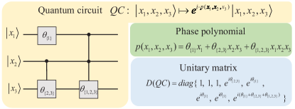
To characterize the functionality of the MCZR circuit, we first establish a useful circuit-polynomial correspondence and then illustrate its unitary matrix representation.
The MCZR gate family for an -qubit quantum circuit can be denoted as , with being the control set, being the target, and being a -rotation angle parameter. By definition, the action of a MCZR gate on each computational basis state is
| (1) |
The global phase factor in Eq. (III) indicates that the function of gate remains unchanged under any permutation of control and one target qubits in the set . Therefore, we can simply denote each MCZR gate acting on all qubits in a set as such that
| (2) |
In this way, any quantum circuit consisting of MCZR gates , ,…, can transform each basis state as
| (3) |
with
| (4) |
being a associated with the circuit . That is to say, any given -qubit MCZR circuit corresponds to a unique phase polynomial with real coefficients and degree at most .
Now we turn to the unitary matrix representation of -qubit MCZR circuits. Eq. (III) reveals that each MCZR gate can be explicitly expressed as a diagonal unitary matrix of size as
| (5) |
with all its diagonal elements being 1 or . Since all MCZR gates are diagonal and commutative, two or more MCZR gates that act on the same set of qubits in a circuit can be merged into one by just adding their angle parameters. Without loss of generality , in this paper we focus on the non-trivial MCZR circuit such that all the constituent gates have distinct qubit set , and its unique phase polynomial in Eq. (4) exactly has degree and terms with real coefficients being the angle parameters . Accordingly, the circuit in Eq. (III) would function as a diagonal unitary matrix as
| (6) |
with the polynomial defined in Eq. (4). Obviously, two MCZR circuits over different gate sets would implement two distinct diagonal unitary matrices. For clarity, we display an instance circuit with =3 and its polynomial as well as unitary matrix representation in Fig. 1.
IV Optimal synthesis of MCZR circuits
In above section, we have revealed that a MCZR circuit can implement a diagonal unitary matrix. This in turn raises a natural question: can an arbitrary diagonal operator be implemented by a MCZR gate circuit exactly? This is an attractive subject since diagonal unitary matrices have a wide range of applications in quantum computing and quantum information [14, 50, 51, 49, 52].
In this section, we address this issue by proposing a circuit synthesis method to construct an -qubit gate-count optimal MCZR circuit for implementing a size diagonal unitary matrix
| (11) | ||||
| (12) |
with , which also enables the circuit depth optimal for specific cases. In particular, we emphasize that the mentioned in this paper always indicates an optimal value for the gate count and circuit depth rather than optimal results, indicating that our optimal results cannot be improved any more. For convenience, here we rewrite each available gate in Eq. (III) as by associating with an -bit string such that
| (13) |
Theorem 1.
The MCZR gate set for implementing a target diagonal unitary matrix in Eq. (11) with given parameters is unique, and each gate parameter can be computed analytically as
| (14) |
with , , and defined in Section II. Since indicates a trivial identity gate that can be omitted, the optimal gate-count for implementing is thus with from Eq. (14).
Proof.
According to Eq. (13), there are totally 1 different types of gates available to construct a MCZR circuit that functions as Eq. (6), with its phase polynomial in Eq. (4) rewritten as
| (15) |
Since two quantum circuits which differ only by a global phase factor are equivalent, we suppose that a circuit described by Eq. (6) can perform the target diagonal matrix in Eq. (11) as
| (16) |
leading to
| (17) |
with being a global phase factor, in Eq. (15) and defined in Section II. In total, Eq. (17) gives us linear equations as
| (18) |
Thus, if we can solve a set of angle parameters satisfying Eq. (18) for any given , then we obtain a MCZR circuit over the gate set for implementing any in Eq. (11). In the following, we give an exact analytical expression of the solution to Eq. (18) and prove its uniqueness.
The linear equations in Eq. (18) can be succinctly summarized into a standard form as
| (19) |
such that the size coefficient matrix has elements
| (20) |
where the function transforms a binary string into a decimal number as the row or column index of a matrix, and the set about a string is defined in Section II. Consider another size matrix denoted with elements
| (21) |
here we can prove the product of two matrices in Eqs. (21) and (20) as is exactly an identity matrix of size . By definition, the matrix elements of are
| (22) |
For the diagonal element of with and , Eq. (IV) turns into
| (23) |
by taking . For the off-diagonal elements of with and , we have two cases:
At this point, we prove that and thus the square matrix defined in Eq. (21) is the unique inverse matrix of the coefficient matrix in Eq. (19) by the common knowledge of linear algebra. By multiplying both sides of Eq. (19) with and using Eq. (21), we obtain an analytic form of the solutions to Eq. (19) as
| (24) |
with , , and defined in Section II.

In summary, Eq. (IV) represents a unique set of solutions so that the resultant MCZR circuit for implementing in Eq. (11) naturally achieves an optimal gate count. The angle parameter indicates its associated MCZR gate is a trivial identity gate that can be omitted. Therefore, the optimal gate count for realizing any diagonal unitary operator in Eq. (11) is with the gate parameters obtained from Eq. (IV), and in the worst case is when all angle parameters are solved to be non-zero. For clarity, an example with is shown in Figs. 2 (a) and (b). ∎
As a by-product, the uniqueness of the gate set for implementing a diagonal unitary matrix as declared in Theorem 1 gives us Lemma 1.
Lemma 1.
All MCZR gates in are independent, that is, none of them can be decomposed into a combination of the others.
Besides the gate count, the circuit depth is another important circuit cost metric that needs attention, since a reduced circuit-depth means less circuit execution time. A quantum circuit can be represented as a directed acyclic graph (DAG) in which each node corresponds to a circuit’s gate and each edge corresponds to the input/output of a gate. Then the circuit depth is defined as the maximum length of a path flowing from an input of the circuit to an output [53]. Equivalently speaking, is the number of layers of quantum gates that compactly act on disjoint sets of qubits [54, 55]. For example, the depth of the circuit in Fig. 1 with three non-zero angle parameters is . Notice that a set of MCZR gates may form distinct layer configurations with respective circuit depths, as exemplified by the comparison between the depth-4 circuit in Fig. 2(c) and depth-5 circuit in Fig. 2(d). More generally, in Theorem 2 we reveal the optimal circuit depth of any MCZR circuit constructed from pairs of complementary gates as defined in Definition 1.
Definition 1.
We call a pair of MCZR gates and are complementary if and only if they satisfy .
Theorem 2.
The optimal circuit depth of any MCZR circuit constructed from pairs of complementary gates is exactly .
Proof.
Suppose we construct an -qubit MCZR circuit over pairs of complementary gates by arranging them into layers denoted such that all gates in each layer are disjoint. Here we prove the minimum value of is .
For brevity, we denote each gate layer by an -bit string as
| (25) |
and all such strings totally own bits of 0 and 1. On the other hand, the total number of ‘1’ bits in strings representing these gates is . Therefore, we have
| (26) |
and the lower bound of circuit depth as
| (27) |
Obviously, the equality in Eq. (27) can be achieved when every gate layer has a pair of complementary gates, thus forming a circuit with an optimal depth . ∎
A typical application of Theorem 2 is to construct a depth-optimal MCZR circuit over all non-zero gate parameters solved from Theorem 1 for implementing a given diagonal operator. That is, when all these gates are arranged into layers of complementary gates as , ,…, plus a sole gate in , a circuit with an optimal depth is obtained. For clarity, a circuit example with and the optimal depth is shown in Fig. 2(c), while another circuit with a larger depth is shown in Fig. 2(d) for comparison.
Finally, the combination of Theorem 1 and Theorem 2 leads to a pair-wise circuit synthesis method described as Theorem 3.
Theorem 3 (Pair-wise MCZR circuit synthesis).
A MCZR circuit over the gate set for implementing an arbitrary diagonal unitary matrix in Eq. (11) can be synthesized by computing each gate parameter according to Eq. (14) in a pair-wise way as , ,…, , such that . Note that is an identity gate that will not appear in , and thus has an optimal gate count for any . Specifically, has an optimal circuit depth when the implementation of only employs pairs of complementary gates. For example, this theorem gives us the circuit in Fig. 2(c) to implement Fig. 2(a).
In summary, we provide a gate-count optimal circuit synthesis (that is, Theorem 3) for realizing a given diagonal unitary matrix in Eq. (11), which also enables the circuit depth optimal when all obtained non-zero angle parameters correspond to pairs of complementary gates. Furthermore, in the following we consider how to optimize the depth of any other types of MCZR circuits .
V Depth optimization of MCZR circuits
Since all MCZR gates are diagonal and commutative, the task of optimizing the depth of any given MCZR circuit is equivalent to rearranging all its gates into as few disjoint layers as possible. In this section, we propose a gate-exchange strategy together with a flexible algorithm for effectively reducing the circuit depth.
V.1 A gate-exchange strategy for optimizing the circuit depth
First of all, we present a simple but useful strategy in Lemma 2 that can reduce (or retain) the depth of any MCZR circuit.
Lemma 2.
For a depth- MCZR circuit over the gate set , suppose that (1) a pair of complementary gates and are located in two different layers of , and (2) the gate and a subset of gates are located in the same layer of . Then, the exchange of and in would arrange and into one layer, leading to a new depth- circuit with .
We give an intuitive explanation of Lemma 2. In the original depth- circuit , suppose the gate and gates in are located in a layer indexed by , while the gate is located in another layer indexed . Then the exchange of and arranges the former and the latter into the layer and , respectively. Since the gate alone acts on more qubits than any gate in does, such a gate-exchange operation would lead to two possible situations about the resultant circuit : (1) has the same depth as , or (2) some (or all) of the gates in and the gates adjacent to layer can be merged into the same layer, thus causing a depth reduction over .
Based on Lemma 2, we can derive a two-step framework for achieving a depth-optimal MCZR circuit as described in Lemma 3.
Lemma 3.
In principle, the optimal circuit depth of the MCZR circuits constructed from a given gate set with can be achieved by two steps: (1) arrange all pairs of complementary gates in into a depth- configuration, and (2) find a depth-optimal circuit over the other gates. Then is equal to the total depth of these two parts.
A special case of Lemma 3 is Theorem 2, such that gives us . In general, we can accomplish the second step of Lemma 3 by comparing at most different layer configurations and find the depth-optimal circuit over a given gate set . However, for with a moderate value , the number of all possible layer configurations can be quite large and thus the optimal depth is usually hard to determine. To deal with such complicated cases, in the following we further propose a flexible iterative algorithm for optimizing the depth of a circuit with no complementary gates.
V.2 A flexible iterative depth-optimization algorithm
In this section, we propose an iterative algorithm denoted Algorithm 1 for optimizing the depth of MCZR circuits with no complementary gates, and reveal its flexibility with a use case.
The input of Algorithm 1 includes: a given MCZR circuit with its constituent gates located from left to right as a sequence , with being the set of qubits acted upon by the th gate, and an iteration number . The output is a circuit over gates in that has a depth smaller than or equal to that of . Notice that two subroutine functions Greedy_Layer_Formation and Generate_New_GateSeq are introduced here: the former receives a gate sequence and can arrange as many disjoint gates in into each layer as possible to form a circuit layer configuration , while the latter can generate a new gate sequence from a given circuit by extracting and regrouping gates in original layers . Since the application of our greedy layer formation procedure on different sequences over a given MCZR gate set may result in distinct circuits, we will iteratively use these two functions in our main program to seek circuits with the shortest possible depth as follows.
First, since two gates that act on the same qubit must be located in different layers of a circuit, a depth lower bound on all possible circuits constructed from the input gate set can be derived as:
| (28) |
where indicates the number of integer appeared in . Second, we apply the function Greedy_Layer_Formation to the input gate sequence and obtain a new depth- circuit with layer configuration such that . Third, if and , we can further iteratively generate a new gate sequence from the previous circuit via Generate_New_GateSeq, followed by applying Greedy_Layer_Formation to obtain a new circuit of depth in each loop . In this process, we can terminate the loop when getting the optimal depth as . Finally, we choose the circuit with shortest depth among all constructed above as our output depth-optimized circuit . As a result, Algorithm 1 ensures that: (1) , and (2) for two iteration numbers . Therefore, our Algorithm 1 controlled by an iteration number is a flexible depth-optimization algorithm by considering the relation between the reduced depth and optimization time cost.
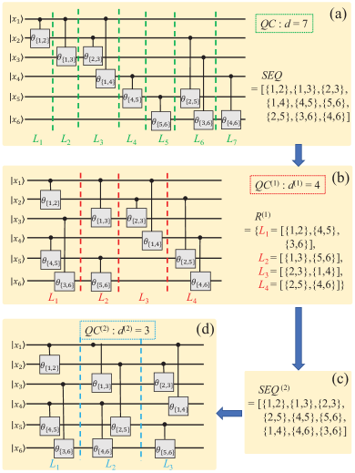
A demonstrative example of Algorithm 1 is shown in Fig. 3. The gate sequence for the 6-qubit and depth-7 circuit consisting of 9 two-qubit gates as shown in Fig. 3(a) is
| (29) |
and we apply Algorithm 1 with to achieve a depth-optimized circuit as follows:
-
(1)
First, we calculate the depth lower bound on circuits for by Eq. (28) as .
-
(2)
Second, we apply Greedy_Layer_Formation to in Eq. (V.2) and obtain a new circuit of depth as shown in Fig. 3(b), which has a layer configuration with
(30) Intuitively, the comparison between the circuit in Fig. 3(a) and in Fig. 3(b) reveals that the working principle of our function Greedy_Layer_Formation is to move the gates in the right column of original circuit to fill the vacancies in the left column as much as possible, thus causing a circuit depth reduction.
- (3)
- (4)
Note that if we apply Algorithm 1 with only to in Fig. 3(a), the resultant depth-optimized circuit would be just in Fig. 3(b). This simple example implies that, if we apply Greedy_Layer_Formation to more distinct gate sequences generated from Generate_New_GateSeq, the more significant depth reduction over the original circuit is likely to occur at the expense of more optimization time. More practical cases of Algorithm 1 will be demonstrated in Section VI.
VI Experimental evaluation
To further evaluate the performances of the proposed synthesis and optimization methods, here we refine them into two explicit workflows and consider their applications to two typical use cases in quantum computing. All experiments are performed with MATLAB 2022a on an Intel Core i5-12500 CPU operating at 3.00 GHz frequency and 16GB of RAM.
VI.1 Workflow of our synthesis and optimization methods
For convenience, here we summarize the main results in Secs. IV and V into the workflow to fulfill two types of tasks as follows:
Task 1: How to construct a gate-count optimal MCZR circuit followed by further depth-optimization for implementing a given diagonal unitary matrix in Eq. (11)?
Workflow 1: First, we synthesize a gate-count optimal MCZR circuit according to Theorem 3 with gates, which includes two parts: (i) layers of complementary gates denoted , and (ii) the other gates. Second, we apply Algorithm 1 with a specified parameter to optimize the part (ii) into a depth- circuit . Finally, the overall output circuit is of depth .
Task 2: How to optimize the circuit depth of a given MCZR circuit over the gate set with ?
Workflow 2: First, we perform the gate-exchange operation to according to Lemma 2, which arranges all pairs of complementary gates in into a depth- circuit denoted . Second, we apply Algorithm 1 to the other gates and obtain a circuit of depth . Finally, putting these results together gives a depth-optimized circuit of depth .
In the following, we demonstrate the utility of above workflows for two practical quantum computing tasks: (1) constructing diagonal Hermitian quantum operators, and (2) optimizing the depth of QAOA circuits.
VI.2 Diagonal Hermitian quantum operators
We use to denote an -qubit diagonal Hermitian quantum operator with its diagonal elements being , and there are totally different such operators since and are essentially equivalent. Note that operators of this type act as the oracle operator or fixed operator in the well-known Deutsch-Jozsa algorithm [56, 57], Grover’s algorithm [58] and some recent algorithms showing quantum advantage for string learning and identification [52, 59, 60]. Therefore, an efficient construction of over MCZR gates would facilitate the implementation of relevant quantum algorithms on specific devices [27, 30].
Prior work [35] has revealed that can be synthesized by at most multiple-controlled Pauli gates, that is, MCZR gates with a fixed angle parameter , based on a binary representation and solving linear equations over the binary field . As comparison, here we apply our synthesis and optimization methods to construct circuits for realizing such operators, and to be more specific, our strategies include: pair-wise synthesis method in Theorem 3 (), our Workflow 1 in Sec. VI.1 with (), (), and (), respectively. We perform experiments on all 8, 128, 32768 diagonal Hermitian operators for , respectively, as well as 100 randomly selected ones for each , and compare our results with the previous work. Due to the uniqueness property , our constructed circuits have the same MCZR gate set as that from Ref. [35], and therefore we mainly illustrate our circuit depth reduction. The detailed experimental results are presented in Fig. 4.
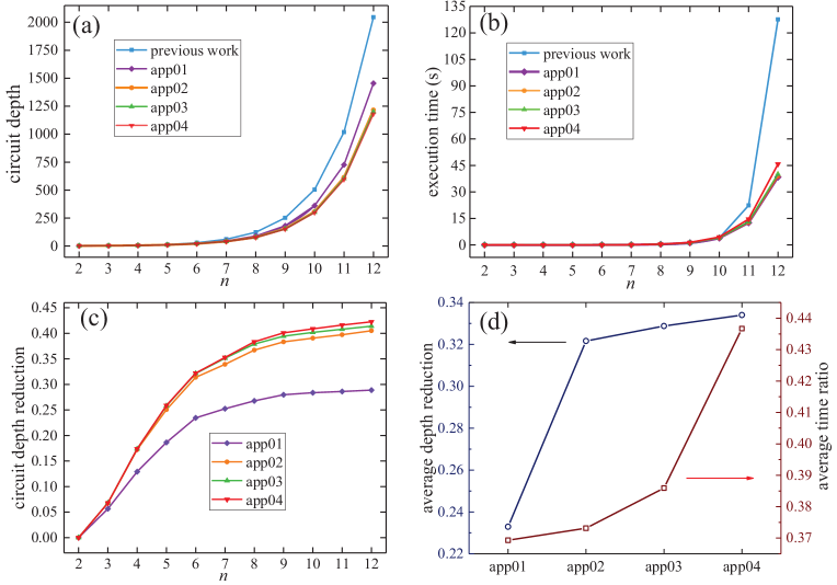
In Fig. 4 (a), we present the average circuit depth of -qubit MCZR circuits () constructed from the previous work [35], our four strategies , , , and by the blue, purple, orange, green, and red curve, respectively. Accordingly, the average execution time of constructing a circuit of size by these strategies are recorded in Fig. 4 (b). Typically, the time growth of our sole circuit synthesis algorithm as a function of agrees well with the total time complexity of calculating Eq. (14), that is, . As comparison, the time of previous work [35] increases more drastically wih , since its most time-consuming procedure for solving linear equations over to determine whether each MCZR gate exists or not would require time scaling roughly as . It is worth noting that all our four strategies have both a reduced circuit depth and less execution time over the previous work. In Fig. 4 (c), the circuit depth reduction curve for each of our strategies shows an explicit upward trend as the circuit size increases, which can achieve as high as 28.88%, 40.51%, 41.40%, 42.27% for constructing a circuit of on average in time 38.40s, 38.79s, 40.16s, and 45.78s, respectively. Also, the usefulness of Algorithm 1 is reflected by observing that can achieve a 11.57% smaller depth over the sole synthesis algorithm at the expense of only 1.03% more time for circuits of , while and give us shorter and shorter depths as increases. Finally, in Fig. 4 (d) we evaluate the overall average performances of our strategies , , , and for all involved circuit instances with , including the average depth reduction of 23.29%, 32.16%, 32.88%, and 33.40%, and the average time ratio of 36.93%, 37.31%, 38.59%, and 43.67% with respect to the previous work, respectively. It seems that for such circuit instances, the average depth-optimization trend would rise slowly as the iteration number in Workflow 1 increases.
In summary, here we demonstrate our Workflow 1 for synthesizing and optimizing MCZR circuits by taking diagonal Hermitian operators as an example, which can show substantial improvement over the previous work in terms of both circuit depth and execution time. In addition, our results empirically validate that a shorter circuit depth is likely to be achieved by increasing the iteration number in Algorithm 1 with more time (see Fig. 4.(d)). In the following, we focus on another example to highlight the flexibility of Algorithm 1 for realizing controllable depth optimization.
VI.3 Phase-separation part in QAOA circuit
Quantum Approximate Optimization Algorithm (QAOA) is a well-known hybrid quantum-classical algorithm designed to solve combinatorial optimization problems. A typical stage of the QAOA circuit for the MaxCut problem consists of three parts: a layer of Hadamard gates, a phase-separation part consisting of gates, and a layer of rotation gates. Here we focus on reducing the depth of the middle part in -qubit MaxCut-QAOA circuits of 3-regular graphs [49] by using our Workflow 2 in Sec. VI.1, which is thus Algorithm 1 for .
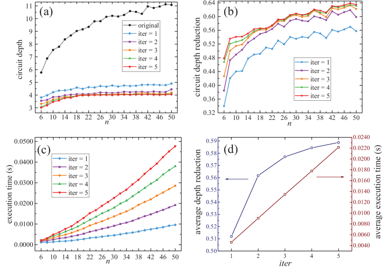
To our knowledge, prior work [49] has used a so-called min-layer formation (MLF) procedure for reducing the number of gate layers in QAOA circuits, which is exactly a particular case of our Algorithm 1 with the iteration number taken as . For comparison, here we apply Algorithm 1 with to optimize such phase-separation part consisting of two-qubit gates in OAOA circuits, respectively. According to the definition of 3-regular graphs such that every vertex is connected to three other vertices, the circuit depth lower bound in Eq. (28) is determined to be 3 for any circuit instance input to Algorithm 1. As an example, the depth optimization of a 6-qubit phase-separation circuit of depth 7 by taking has been presented in Fig. 3. More broadly, here we pick the -qubit circuit instances corresponding to -node 3-regular graphs with being an even number in the range of 6 to 50, and for each size we randomly pick 100 graphs. Thus, a total of MaxCut-QAOA circuit instances have been used for the evaluation. The experimental results are presented in Fig. 5.
The average circuit depth of 100 original randomly selected -qubit QAOA circuits for is shown as the black curve in Fig. 5 (a), where the blue, purple, orange, green, and red curves indicate the optimized circuit depth obtained from performing Algorithm 1 with (that is, MLF procedure in Ref. [49]) as well as , respectively. Specifically, the optimized circuit depths as indicated by the red line in Fig. 5(a) with grows quite slowly and ranges from 3.00 to 4.05 for . Accordingly, Figs. 5 (b) and 5(c) show the circuit depth reduction and execution time for each instance with size on average, respectively. In particular, the depth-reduction curve for each setting is growing overall as the circuit size increases, and can achieve as high as 63.45% for in time less than 0.05s when adopting . Furthermore, Fig. 5 (d) shows the overall performance of Algorithm 1 with on all 2300 circuit instances, where on average we can achieve a depth reduction of 51.19%, 56.17%, 57.71 %, 58.44%, and 58.88% over one original randomly selected QAOA circuit instance by using time of 0.0046s, 0.0090s, 0.0135s, 0.0178s and 0.0222s for each , respectively. Notably, the average execution time scales nearly linearly as increases from 1 to 5, and the average depth obtained from is 15.55% smaller than that from at the expense of 4.81X increase in time. Once again, these results reflect the flexibility of Algorithm 1 as it can achieve a shorter circuit depth at the expense of more execution time. Therefore, for dealing with such QAOA-circuit case one can take Algorithm 1 with gradually increasing the iteration number to seek the best possible results.
Finally, we point out the expense of depth-optimization time overhead is especially worthwhile in the use-case of QAOA since the obtained circuit needs to be executed on the quantum hardware many times for solving the MaxCut problem, and thus a shorter circuit depth obtained from the precedent optimization procedure could save a large amount of time in the subsequent process of running the QAOA circuit. As a result, our depth-optimized circuits might be executed on the scalable quantum processor with non-local connectivity [61], or can act as a better starting point for possible further circuit compilation if needed [49].
VII Discussion and Conclusion
In this study, we present a systematic study of quantum circuits over multiple-control -rotation gates with continuous parameters. Based on an established polynomial representation, we derive a gate-count optimal synthesis of such circuits for implementing any diagonal unitary matrix, which also enables the circuit depth optimal for specific MCZR circuits. Furthermore, we propose practical optimization strategies for reducing the circuit depth of any given MCZR circuit, which can show substantial performance improvement over prior works for typical examples in quantum computing. Compared to the conventional study of implementing diagonal unitary operators over the single- and two-qubit gate set [62, 63, 64], here we provide an alternative scheme by utilizing a multiqubit gate set as the computational primitives, which would match the quantum experimental progress in certain directions, such as neutral atoms [22] and superconducting systems [27, 29]. In addition, note that above techniques are raised for dealing with general cases, we point out there may also exist other useful ideas aimed at special-case circuits. For example, particular quantum graph states [54] or hypergraph states [65] can be prepared with linearly many MCZR gates and constant depth by observing their underlying lattice graphs. Readers of interest could explore more about such specific cases.
Although this paper mainly focuses on quantum circuits over MCZR gates, it may enlighten the research on other types of circuits as well. First, the circuit-polynomial correspondence put forward to characterize MCZR circuits extends the concept of phase polynomial representation [66], again implying that an appropriate representation could facilitate circuit synthesis and/or optimization. Second, the depth-optimization strategies introduced in Section V are actually suitable for any quantum circuit over commuting gates, such as IQP (instantaneous quantum polynomial-time) circuits used to demonstrate quantum advantage [67]. Finally, this study sheds light on implementing diagonal unitary operators over other available gate sets, such as the multiply-controlled Toffoli gates acting on fewer qubits by considering gate simulation [4]. Therefore, we would like to investigate these interesting topics in the future work.
Acknowledgements.
This work was supported by the National Natural Science Foundation of China (Grant Nos. 62102464, 62272492, 61772565), the Guangdong Basic and Applied Basic Research Foundation (Grant No. 2020B1515020050), and Project funded by China Postdoctoral Science Foundation (Grant Nos. 2020M683049, 2021T140761). We appreciate Dr. Li Zhang from South China Normal University for useful discussions on the data analysis.References
- Preskill [2018] J. Preskill, Quantum computing in the NISQ era and beyond, Quantum 2, 79 (2018).
- Leymann and Barzen [2020] F. Leymann and J. Barzen, The bitter truth about gate-based quantum algorithms in the NISQ era, Quantum Sci. Technol. 5, 044007 (2020).
- Bharti et al. [2022] K. Bharti, A. Cervera-Lierta, T. H. Kyaw, T. Haug, S. Alperin-Lea, A. Anand, M. Degroote, H. Heimonen, J. S. Kottmann, T. Menke, et al., Noisy intermediate-scale quantum algorithms, Rev. Mod. Phys. 94, 015004 (2022).
- Barenco et al. [1995] A. Barenco, C. H. Bennett, R. Cleve, D. P. DiVincenzo, N. Margolus, P. Shor, T. Sleator, J. A. Smolin, and H. Weinfurter, Elementary gates for quantum computation, Phys. Rev. A 52, 3457 (1995).
- Li et al. [2022a] H.-S. Li, P. Fan, H. Xia, and G.-L. Long, The circuit design and optimization of quantum multiplier and divider, Sci. China-Phys. Mech. Astron. 65, 1 (2022a).
- Rossi et al. [2013] M. Rossi, M. Huber, D. Bruß, and C. Macchiavello, Quantum hypergraph states, New J. Phys. 15, 113022 (2013).
- Lin [2018] Q. Lin, Multiple multicontrol unitary operations: Implementation and applications, SCIENCE CHINA Physics, Mechanics & Astronomy 61, 1 (2018).
- Park et al. [2019] D. K. Park, F. Petruccione, and J.-K. K. Rhee, Circuit-based quantum random access memory for classical data, Sci. Rep. 9, 1 (2019).
- De Veras et al. [2020] T. M. De Veras, I. C. De Araujo, D. K. Park, and A. J. Da Silva, Circuit-based quantum random access memory for classical data with continuous amplitudes, IEEE Trans. Comput. 70, 2125 (2020).
- Vandersypen et al. [2001] L. M. Vandersypen, M. Steffen, G. Breyta, C. S. Yannoni, M. H. Sherwood, and I. L. Chuang, Experimental realization of shor’s quantum factoring algorithm using nuclear magnetic resonance, Nature 414, 883 (2001).
- Figgatt et al. [2017] C. Figgatt, D. Maslov, K. A. Landsman, N. M. Linke, S. Debnath, and C. Monroe, Complete 3-qubit Grover search on a programmable quantum computer, Nat. Commun. 8, 1 (2017).
- Yoder et al. [2014] T. J. Yoder, G. H. Low, and I. L. Chuang, Fixed-point quantum search with an optimal number of queries, Phys. Rev. Lett. 113, 210501 (2014).
- Roy et al. [2022] T. Roy, L. Jiang, and D. I. Schuster, Deterministic Grover search with a restricted oracle, Phys. Rev. Res. 4, L022013 (2022).
- Qiang et al. [2016] X. Qiang, T. Loke, A. Montanaro, K. Aungskunsiri, X. Zhou, J. L. O’Brien, J. B. Wang, and J. C. Matthews, Efficient quantum walk on a quantum processor, Nat. Commun. 7, 1 (2016).
- Yoder et al. [2016] T. J. Yoder, R. Takagi, and I. L. Chuang, Universal fault-tolerant gates on concatenated stabilizer codes, Phys. Rev. X 6, 031039 (2016).
- Chao and Reichardt [2018] R. Chao and B. W. Reichardt, Fault-tolerant quantum computation with few qubits, npj Quant. Inf. 4, 1 (2018).
- Qiskit Circuit Library [2023] Qiskit Circuit Library, https://qiskit.org/documentation/apidoc/circuit_library.html (2023).
- PennyLane QML [2023] PennyLane QML, https://docs.pennylane.ai/en/stable/code/qml.html (2023).
- Martinez et al. [2016] E. A. Martinez, T. Monz, D. Nigg, P. Schindler, and R. Blatt, Compiling quantum algorithms for architectures with multi-qubit gates, New J. Phys. 18, 063029 (2016).
- Mandviwalla et al. [2018] A. Mandviwalla, K. Ohshiro, and B. Ji, Implementing Grover’s algorithm on the IBM quantum computers, in 2018 IEEE International Conference on Big Data (2018) pp. 2531–2537.
- Monz et al. [2009] T. Monz, K. Kim, W. Hänsel, M. Riebe, A. Villar, P. Schindler, M. Chwalla, M. Hennrich, and R. Blatt, Realization of the quantum Toffoli gate with trapped ions, Phys. Rev. Lett. 102, 040501 (2009).
- Levine et al. [2019] H. Levine, A. Keesling, G. Semeghini, A. Omran, T. T. Wang, S. Ebadi, H. Bernien, M. Greiner, V. Vuletić, H. Pichler, et al., Parallel implementation of high-fidelity multiqubit gates with neutral atoms, Phys. Rev. Lett. 123, 170503 (2019).
- Mičuda et al. [2013] M. Mičuda, M. Sedlak, I. Straka, M. Miková, M. Dušek, M. Ježek, and J. Fiurášek, Efficient experimental estimation of fidelity of linear optical quantum Toffoli gate, Phys. Rev. Lett. 111, 160407 (2013).
- Dong et al. [2018] L. Dong, S.-L. Wang, C. Cui, X. Geng, Q.-Y. Li, H.-K. Dong, X.-M. Xiu, and Y.-J. Gao, Polarization Toffoli gate assisted by multiple degrees of freedom, Opt. Lett. 43, 4635 (2018).
- Ru et al. [2021] S. Ru, Y. Wang, M. An, F. Wang, P. Zhang, and F. Li, Realization of a deterministic quantum Toffoli gate with a single photon, Opt. Lett. 103, 022606 (2021).
- Fedorov et al. [2012] A. Fedorov, L. Steffen, M. Baur, M. P. da Silva, and A. Wallraff, Implementation of a Toffoli gate with superconducting circuits, Nature 481, 170 (2012).
- Song et al. [2017] C. Song, S.-B. Zheng, P. Zhang, K. Xu, L. Zhang, Q. Guo, W. Liu, D. Xu, H. Deng, K. Huang, et al., Continuous-variable geometric phase and its manipulation for quantum computation in a superconducting circuit, Nat. Commun. 8, 1 (2017).
- Kim et al. [2022] Y. Kim, A. Morvan, L. B. Nguyen, R. K. Naik, C. Jünger, L. Chen, J. M. Kreikebaum, D. I. Santiago, and I. Siddiqi, High-fidelity three-qubit iToffoli gate for fixed-frequency superconducting qubits, Nat. Phys. 18, 783 (2022).
- Roy et al. [2020] T. Roy, S. Hazra, S. Kundu, M. Chand, M. P. Patankar, and R. Vijay, Programmable superconducting processor with native three-qubit gates, Phys. Rev. Appl. 14, 014072 (2020).
- Hill et al. [2021] A. D. Hill, M. J. Hodson, N. Didier, and M. J. Reagor, Realization of arbitrary doubly-controlled quantum phase gates, arXiv:2108.01652 (2021).
- Reed et al. [2012] M. D. Reed, L. DiCarlo, S. E. Nigg, L. Sun, L. Frunzio, S. M. Girvin, and R. J. Schoelkopf, Realization of three-qubit quantum error correction with superconducting circuits, Nature 482, 382 (2012).
- Maslov et al. [2007] D. Maslov, G. W. Dueck, and D. M. Miller, Techniques for the synthesis of reversible Toffoli networks, ACM Trans. Des. Autom. Electron. Syst. 12, 42 (2007).
- Große et al. [2009] D. Große, R. Wille, G. W. Dueck, and R. Drechsler, Exact multiple-control Toffoli network synthesis with SAT techniques, IEEE Trans. Comput.-Aided Des. Integr. Circuits Syst. 28, 703 (2009).
- Sasanian et al. [2012] Z. Sasanian, R. Wille, and D. M. Miller, Realizing reversible circuits using a new class of quantum gates, in Proceedings of the 49th Annual Design Automation Conference, DAC ’12 (ACM, 2012) p. 36–41.
- Houshmand et al. [2014] M. Houshmand, M. S. Zamani, M. Sedighi, and M. Arabzadeh, Decomposition of diagonal Hermitian quantum gates using multiple-controlled Pauli Z gates, ACM J. Emerg. Technol. Comput. Syst. 11, 1 (2014).
- Maslov [2016] D. Maslov, Advantages of using relative-phase Toffoli gates with an application to multiple control Toffoli optimization, Phys. Rev. A 93, 022311 (2016).
- Nakata et al. [2014] Y. Nakata, M. Koashi, and M. Murao, Generating a state t-design by diagonal quantum circuits, New J. Phys. 16, 053043 (2014).
- Gachechiladze et al. [2019] M. Gachechiladze, O. Gühne, and A. Miyake, Changing the circuit-depth complexity of measurement-based quantum computation with hypergraph states, Phys. Rev. A 99, 052304 (2019).
- Banerjee et al. [2020] S. Banerjee, A. Mukherjee, and P. K. Panigrahi, Quantum blockchain using weighted hypergraph states, Phys. Rev. Res. 2, 013322 (2020).
- Möttönen et al. [2004] M. Möttönen, J. J. Vartiainen, V. Bergholm, and M. M. Salomaa, Quantum circuits for general multiqubit gates, Phys. Rev. Lett. 93, 130502 (2004).
- Bergholm et al. [2005] V. Bergholm, J. J. Vartiainen, M. Möttönen, and M. M. Salomaa, Quantum circuits with uniformly controlled one-qubit gates, Phys. Rev. A 71, 052330 (2005).
- Maslov and Nam [2018] D. Maslov and Y. Nam, Use of global interactions in efficient quantum circuit constructions, New J. Phys. 20, 033018 (2018).
- Roy et al. [2018] T. Roy, M. Chand, A. Bhattacharjee, S. Hazra, S. Kundu, K. Damle, and R. Vijay, Multimode superconducting circuits for realizing strongly coupled multiqubit processor units, Phys. Rev. A 98, 052318 (2018).
- Barnes et al. [2017] E. Barnes, C. Arenz, A. Pitchford, and S. E. Economou, Fast microwave-driven three-qubit gates for cavity-coupled superconducting qubits, Phys. Rev. B 96, 024504 (2017).
- Su et al. [2018] S. L. Su, H. Z. Shen, E. Liang, and S. Zhang, One-step construction of the multiple-qubit rydberg controlled-phase gate, Phys. Rev. A 98, 032306 (2018).
- Khazali and Mølmer [2020] M. Khazali and K. Mølmer, Fast multiqubit gates by adiabatic evolution in interacting excited-state manifolds of rydberg atoms and superconducting circuits, Phys. Rev. X 10, 021054 (2020).
- Glaser et al. [2023] N. J. Glaser, F. Roy, and S. Filipp, Controlled-controlled-phase gates for superconducting qubits mediated by a shared tunable coupler, Phys. Rev. Appl. 19, 044001 (2023).
- Su et al. [2022] Q.-P. Su, Y. Zhang, L. Bin, and C.-P. Yang, Efficient scheme for realizing a multiplex-controlled phase gate with photonic qubits in circuit quantum electrodynamics, Front. Phys. 17, 53505 (2022).
- Alam et al. [2020] M. Alam, A. Ash-Saki, and S. Ghosh, An efficient circuit compilation flow for quantum approximate optimization algorithm, in 2020 57th ACM/IEEE Design Automation Conference (DAC) (2020) pp. 1–6.
- Kassal et al. [2008] I. Kassal, S. P. Jordan, P. J. Love, M. Mohseni, and A. Aspuru-Guzik, Polynomial-time quantum algorithm for the simulation of chemical dynamics, Proc. Natl. Acad. Sci. U.S.A. 105, 18681 (2008).
- Nakata and Murao [2014] Y. Nakata and M. Murao, Diagonal quantum circuits: their computational power and applications, Eur. Phys. J. Plus 129, 152 (2014).
- Xu et al. [2023] Y. Xu, S. Zhang, and L. Li, Quantum algorithm for learning secret strings and its experimental demonstration, Phys. A Stat. Mech. its Appl. 609, 128372 (2023).
- Amy et al. [2013] M. Amy, D. Maslov, M. Mosca, and M. Roetteler, A meet-in-the-middle algorithm for fast synthesis of depth-optimal quantum circuits, IEEE Trans. Comput.-Aided Des. Integr. Circuits Syst. 32, 818 (2013).
- Bravyi et al. [2018] S. Bravyi, D. Gosset, and R. König, Quantum advantage with shallow circuits, Science 362, 308 (2018).
- Abdessaied and Drechsler [2016] N. Abdessaied and R. Drechsler, in Reversible and Quantum Circuits: Optimization and Complexity Analysis (Springer, Berlin, 2016) Chap. 2, p. 35.
- Deutsch and Jozsa [1992] D. Deutsch and R. Jozsa, Rapid solution of problems by quantum computation, Proc. R. Soc. Lond. A. 439, 553 (1992).
- Collins et al. [1998] D. Collins, K. W. Kim, and W. C. Holton, Deutsch-Jozsa algorithm as a test of quantum computation, Phys. Rev. A 58, R1633 (1998).
- Grover [1996] L. K. Grover, A fast quantum mechanical algorithm for database search, in Proceedings of the Twenty-Eighth Annual ACM Symposium on Theory of Computing, STOC ’96 (ACM, 1996) p. 212–219.
- Li et al. [2022b] L. Li, J. Luo, and Y. Xu, Playing mastermind on quantum computers, arXiv: 2207.09356 (2022b).
- Huang et al. [2022] X. Huang, S. Zhang, and L. Li, Quantum algorithms for identifying hidden strings with applications to matroid problems, arXiv: 2211.10667 (2022).
- Bluvstein et al. [2022] D. Bluvstein, H. Levine, G. Semeghini, T. T. Wang, S. Ebadi, M. Kalinowski, A. Keesling, N. Maskara, H. Pichler, M. Greiner, V. Vuletić, and M. D. Lukin, A quantum processor based on coherent transport of entangled atom arrays, Nature 604, 451 (2022).
- Bullock and Markov [2004] S. S. Bullock and I. L. Markov, Asymptotically optimal circuits for arbitrary -qubit diagonal computations, Quantum Inf. Comput. 4, 27 (2004).
- Welch et al. [2014] J. Welch, D. Greenbaum, S. Mostame, and A. Aspuru-Guzik, Efficient quantum circuits for diagonal unitaries without ancillas, New J. Phys. 16, 033040 (2014).
- Zhang et al. [2022] S. Zhang, K. Huang, and L. Li, Automatic depth-optimized quantum circuit synthesis for diagonal unitary matrices with asymptotically optimal gate count, arXiv:2212.01002 (2022).
- Liu and Winter [2022] Z.-W. Liu and A. Winter, Many-body quantum magic, PRX Quantum 3, 020333 (2022).
- Nam et al. [2018] Y. Nam, N. J. Ross, Y. Su, A. M. Childs, and D. Maslov, Automated optimization of large quantum circuits with continuous parameters, npj Quantum Inf. 4, 1 (2018).
- Bremner et al. [2017] M. J. Bremner, A. Montanaro, and D. J. Shepherd, Achieving quantum supremacy with sparse and noisy commuting quantum computations, Quantum 1, 8 (2017).