[7]G^ #1,#2_#3,#4(#5 #6| #7) \fail
Secrecy Design of Indoor Visible Light Communication Network under Downlink NOMA Transmission
Abstract
In this work, we investigate the transmission sum rate as well as the secrecy sum rate of indoor visible light communication (VLC) networks for mobile devices with the power domain non-orthogonal multiple access (NOMA) transmission, where multiple legitimate users are equipped with photodiodes (PDs). We introduce a body blockage model of the legitimate users as well as the eavesdropper to focus on the case where the communications from transmitting light-emitting diodes (LEDs) to receiving devices are blocked by the bodies of receiving users. Furthermore, in order to improve the secrecy without any knowledge of the channel state information (CSI) of the eavesdropper, a novel LED arrangement is introduced to reduce the overlapping area covered by LED units supporting different users. We also propose two LED operation strategies, called simple and smart LED linking, and evaluate their performance against the conventional broadcasting in terms of transmission sum rate and secrecy sum rate. Through computer simulations, the superiority of our proposed strategies is demonstrated.
Index Terms:
Body blockage model, non-orthogonal multiple access (NOMA), passive eavesdropper, physical layer security (PLS), visible light communication (VLC).I Introduction
Visible light communication (VLC) is a promising technology that has been introduced as an auspicious solution for beyond fifth-generation (B5G) and sixth-generation (6G) [1]. While functioning in the visible light spectrum, VLC emits light not only for illumination but also for data transmission. Due to its potentially high data rate, VLC has gained significant interest in recent decades [2]. Exploiting a contemporary infrastructure used for illumination, VLC is implemented by modulating the data through the light intensity of light-emitting diodes (LEDs), also known as intensity modulation (IM). Since radio frequency (RF) radiation should be strictly monitored, VLC has been seen as an intriguing RF communication complement.
Nevertheless, for future wireless networks based on VLC, an efficient multiple-access scheme needs to be established. Non-orthogonal multiple access (NOMA) has received significant recent attention due to its high spectral efficiency compared to the conventional orthogonal multiple access (OMA) techniques [3, 4, 5]. In contrast to OMA, NOMA allocates the same time-frequency resources to multiple users, which enables the efficient utilization of the limited frequency spectrum [6]. NOMA is generally divided into the two main categories, i.e., code domain NOMA and power domain NOMA. Throughout this work, we focus on power domain NOMA, where its downlink can be implemented by multi-user superposition coding at the transmitter and successive interference cancellation (SIC) at the receivers [7].
In addition, physical layer security (PLS) enables secure communication by leveraging the randomness of wireless channels, such as fading, noise, and interference. The objective of PLS is to utilize the stochastic properties of wireless channels in order to provide secure communication, which was initially introduced in [8]. In particular, the secrecy ensured by PLS is limited to the case where the channel to the legitimate user is better than that of the eavesdropper, i.e., the channel of the eavesdropper should be degraded compared to the channel of the legitimate user. Under this condition, secure information transmission against eavesdropping is possible without relying on symmetric keys or complicated encryption/decryption algorithms [9, 10, 11, 12].
I-A Literature Review and Motivation
In recent years, a variety of signal processing approaches has been investigated for VLC-aided PLS systems such as beamforming [13, 14, 15], precoding [16, 17], artificial optical jamming [18], and polar code-based secure coding [19]. Regarding mathematical tools, stochastic geometry theory is used to derive the average secrecy capacity of the system while the users are randomly distributed across the room [20]. Convex optimization theory can be used to enhance the secrecy performance of VLC systems that are subject to various illumination constraints, e.g., the LED optical power constraint [21], the peak power constraint to reduce eye damage [13], and the light energy harvesting and dimming control constraint [14]. On the other hand, most of the research on PLS for VLC networks was performed against external malicious eavesdroppers [17, 20, 21], while several previous works have focused on the transmission of confidential information, i.e., users are kept ignorant about the information not intended for them [16]. Based on the properties of VLC channels, these studies considered applications of beamforming and jamming for enhancing the secrecy in the physical layer with high computational complexity. In practice, however, the position of the passive eavesdropper is unknown since it never responds to the transmission mechanism. Furthermore, it is still highly complex for broadcasting systems to implement beamforming schemes in VLC transmission. With respect to LED arrangements, most works adopt a square lattice alignment to improve illuminance [22]. However, in broadcasting VLC, such an arrangement may degrade communication reliability since interference may occur in the overlapping areas served by multiple LED devices with each transmitting different signals.
In contrast, the internal eavesdropper may bring critical security issues while the devices have access to the system using shared information with untrusted users in multiple access scenarios. Several recent works have investigated PLS with an internal eavesdropper, i.e., untrusted user scenario [23, 24, 25]. Furthermore, PLS with VLC-enabled NOMA is investigated in [26, 27, 28, 29]. Specifically, in [26], a precise expression of secure outage probability was derived for NOMA-enabled multi-user multiple-input single-output (MISO) VLC system. In [27], secure transmission of MISO with NOMA under VLC with known and unknown channel state information (CSI) of eavesdroppers was investigated. In [28], secrecy performance of a NOMA-enabled VLC system in the presence of an active eavesdropper was demonstrated. In [29], secrecy performance is enhanced in the NOMA-enabled VLC system by the pseudo user, which interrupts the SIC process of the eavesdropper. However, for passive eavesdroppers, it is challenging to acquire their exact geometric locations due to the absence of information exchange.
I-B Contributions
Inspired by the above-mentioned state-of-the-art studies, our work focuses on VLC-enabled PLS systems without any knowledge of the eavesdropper. The main contributions111 The shorter version of this work was presented at the 2023 IEEE Wireless Communications and Networking Conference (WCNC) in [30], and we additionally propose a new strategy (i.e., smart LED linking strategy) as well as a new power allocation scheme based on an estimated maximum sum rate in order to improve the secrecy performance. of this work are summarized as follows:
-
•
A mobile device with the statistical model was introduced and developed in [31, 32]. A model where the light path from LED to PD may be blocked by the bodies of users, called body blockage model in this manuscript, was investigated in the work [32]. As an extension of these previous works, in this study, we propose a general geometric blockage model adopted with the VLC secrecy model in the presence of a passive eavesdropper and evaluate both the transmission and secrecy performance. Moreover, in our model assumption, the system does not have access to the CSI of the eavesdropper and has no knowledge if users’ bodies, including the eavesdropper’s, are obstructing light paths.
-
•
We propose a new power allocation scheme based on NOMA in order to maximize the transmission sum rate of the legitimate users based only on their location and statistical radiation angle, i.e., the system is unaware of the azimuth and polar angles of the devices, which are important for detecting whether the light is blocked or not. Furthermore, we compare two power allocation schemes through computer simulation in terms of the estimation errors, i.e., the fixed and optimal power allocation schemes based on the estimated maximum sum rate.
-
•
In order to decrease the overlapping area of different LED units, we propose a new LED arrangement, where LEDs are placed in the form of an equilateral triangle lattice for PLS requirements. Moreover, two transmission strategies, referred to as simple and smart LED linking strategies, are proposed for this LED arrangement to investigate the trade-off between throughput and secrecy. The comparison between transmission and secrecy performances of our LED arrangement and the method where LEDs are placed in a square [22] was conducted, and improvements were observed in simulation results.
I-C Paper Organization
The rest of this paper is organized as follows. Section II describes the system model including the channel model as well as the body blockage model considered throughout this work, and Section III describes the NOMA signal models and performance metrics. In Section IV, the proposed transmission strategies of secure NOMA in VLC are described. Simulation results are presented and discussed in Section V. Finally, conclusions are drawn in Section VI.
Notation
Throughout the paper, the following notations are adopted: for all , is the expectation operator, is the circular-symmetric Gaussian random distribution with mean and variance , and is the Gaussian-Q function[33, (B.20)].
II System and Channel Model
In this section, we describe our system model as well as VLC channel model.
II-A System Model
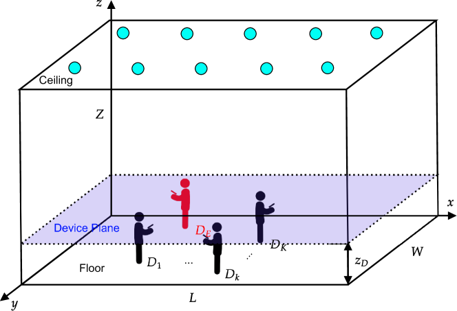
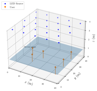
As shown in Fig. 1, we consider an indoor downlink scenario in the room size of length , width , and height , where LED sources serve legitimate users with the index set , as well as an eavesdropper with the index , and each of them has a single PD receiver. We assume that the system is not aware of the location of the eavesdropper. For simplicity, we also assume that all the receiving devices are located at the same height from the floor, and define the device plane as , valid for and , in the three-dimensional (3D) Cartesian coordinates. Let denote the position corresponding to the th LED source in the polar coordinates for . We define with as the positions representing the corresponding PD, where is the set of the indices corresponding to all the PD receivers in the room. In addition, we assume that all the bodies of users as well as the eavesdropper are modeled as cylinders with height and radius as in [34, 35, 32].
II-B Channel Model
In this subsection, we define the VLC channel between an LED-PD transceiver pair with emphasis on the effect that is caused by the users’ bodies.
II-B1 VLC Channel
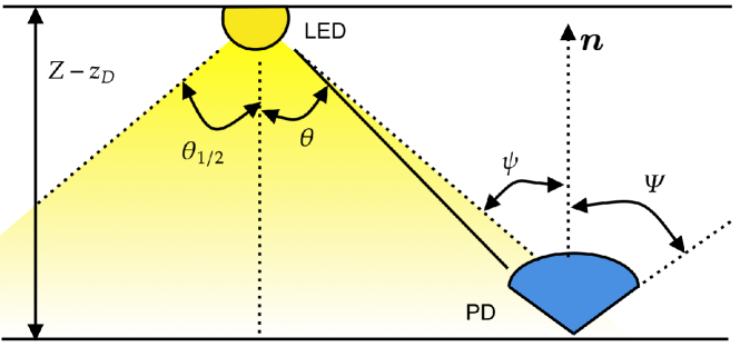
In Fig. 2, we illustrate the geometric relationship between LED and PD with the normal direction of its photosensitive surface . Most of the existing studies on VLC systems consider the line-of-sight (LoS) component in VLC channel models and ignore the non-line-of-sight (NLoS) component due to a huge diffuse component gap between LoS and NLoS components [36, 37, 38]. Subsequently, assuming that the considered LEDs have Lambertian emission patterns, the channel gain between and with is expressed as [36]
| (1) |
where is the effective area of the photosensitive surface of PD receivers, is the radiation angle from to , is the incidence angle from to , is the received field of view (FoV) of PD receivers, is the order of the Lambertian emission with half illuminance angle of LED transmitter , is the Euclidean distance between and , is a binary indicator function for an event , and represents the gain of the optical concentrator with reflective index , expressed as
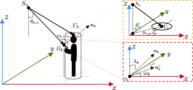
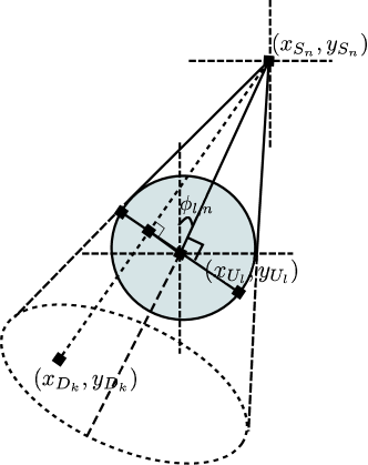
The notation in Section II-B1 represents the event that the is not blocked by the body of with a given azimuth angle , i.e., the angle between the XOY projection of the direction vector and -axis. In order to facilitate the understanding of these geometric parameters, we plot the geometric relations of , , and in Fig. 3, where is the position of the top center of the cylinder for . The coordinate parameters and are respectively calculated as
| (2) | ||||
| (3) |
where is the distance between the center of cylinder and the PD of its mobile device, is the polar angle of , and is the azimuth angle between the line from to and -axis [39]. Moreover, the incidence angle in Section II-B1 can be obtained by the position of as well as , azimuth angle , and polar angle , i.e., [31]
| (4) |
Additionally, based on the statistical model of the orientation of mobile devices with walking activities situation in [31], we set as a uniform random variable over the interval to , and as a Gaussian random variable with a mean of and a standard deviation of .
II-B2 Body Blockage Model
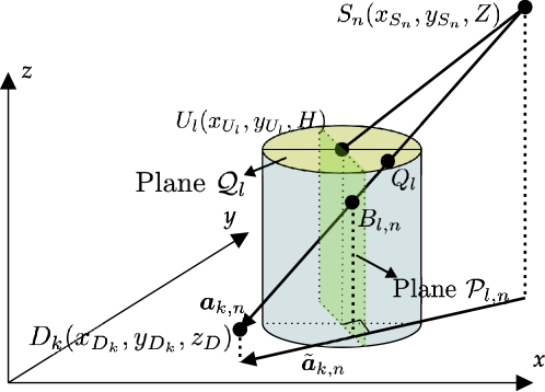
The presence of the body of users as well as the eavesdropper inside an indoor environment may certainly affect the channel characteristics and the communication performance of a VLC system. In fact, the channel gain of the PD devices is affected not only by its geometric parameters but also by the shadows of the human bodies. Subsequently, we focus on the event in Section II-B1 with the corresponding parameters: LED , PD , and the human body of , i.e., , where . As demonstrated in Fig. 4, let us define as a vector of light from to with the projection on the XOY plane . Moreover, we define two planes and , where contains the point and its unit normal vector is , and contains point with its unit normal vector for a real-valued factor . The projection area of the vertical cylinder with the four vertices on the plane is a rectangle with their coordinates given by
| (5a) | ||||
| (5b) | ||||
| (5c) | ||||
| (5d) | ||||
where is the azimuth angle between and , defined as
| (6) |
Next, the intersection point of a line and a plane satisfies the following Lemma:
Lemma 1.
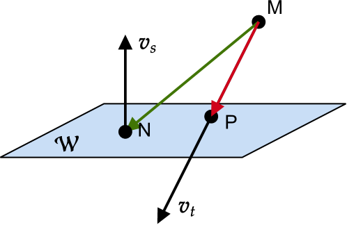
As shown in Fig. 5, we assume that in Euclidean space, the vector passes through the point , and plane contains the point . If the plane also contains the point with one of the normal vectors , the vector satisfies
| (7) |
where the inner product of and satisfies
| (8) |
Proof.
See Appendix A. ∎
We define as the intersection of vector and plane , and as the intersection of vector and plane , where their coordinates can be respectively derived by Lemma 1, i.e.,
| (9) | ||||
| (10) |
Therefore, the event in Section II-B1 can be determined by the following proposition:
Proposition 1.
If the vector is blocked by the cylinder body of user , (i.e., the event is false), at least one of the following conditions should be satisfied;
-
1.
The intersection point should located on of the top base area of cylinder , i.e., it should satisfy that
(11) -
2.
The intersection point should be in the area of rectangle , i.e., it should satisfy all of the following inequalities
(12)
Otherwise, it is not blocked by the cylinder (i.e., the event is true).
III NOMA Signal Models and Performance Metrics
In this section, we describe the NOMA signal model for our proposed VLC transmission system, and introduce performance metrics of the transmission and secrecy sum rate.
III-A NOMA Signal Models
We assume that the transmission signals by LED transmitters are the direct current (DC) biased signals [22]. For convenience, we define the subset of as , which contains the user indices transmitted from the th LED , i.e., . The transmitted symbol from the th LED, denoted by , is a zero-mean Gaussian signal superimposed on a fixed bias current , where the fixed bias is used for illumination. Following the definition in [22], we have that
| (13) |
where represents the total transmission power at each LED, and is the modulated message signal intended for by , which is assumed to be a Gaussian random variable with zero-mean and unit variance222It is worth noting that the cumulative distribution function (CDF) of can be expressed as . Therefore, provided that is sufficiently large, the probability of negative could be ignored., i.e., , represents the allocated power ratio for and fulfills that
| (14) |
Therefore, after removing the DC bias, the received information by for , can be respectively formulated as
| (15) |
where is the channel coefficient from to defined in Section II-B1, and is the real additive white Gaussian noise (AWGN) with variance at , i.e., .
III-B Transmission and Secrecy Sum Rate
We assume that each device can decode its information with perfect SIC, i.e., there is no residual interference after the SIC process. The device first detects the symbol with the highest received power, and then starts the SIC process by treating the other symbols as additional Gaussian noise terms. The transmission rate of PD for is evaluated as [40]
| (16) |
where the scaling factor is due to the Hermitian symmetry, is the set containing with , i.e., , is defined as the set consisting of set which includes index , expressed as
| (17) |
and is the received signal-to-interference-plus-noise ratio (SINR) at the th user under the assumption of the perfect SIC, which is defined as
| (18) |
where is the cardinality of the set , and the sets and contain indexes of LEDs, defined as
| (19) | ||||
| (20) |
The eavesdropper wiretaps information sent from to during the downlink transmission period and employs the same decoding process as performed at legitimate users. The transmission rate that can be wiretapped by the eavesdropper from the data intended for the th user via eavesdropper’s channel is evaluated as
| (21) |
where denotes the SINR of wiretapped signal to the th user by the eavesdropper, defined as
| (22) |
In this work, the transmission sum rate among the legitimate users, as well as the secrecy sum rate, are respectively defined as [41]
| (23) | ||||
| (24) |
IV Transmission Strategies and Power Allocation Schemes
In this section, we introduce three transmission strategies and two power allocation schemes applied in this work.
IV-A Transmission Strategies
In this subsection, we describe three transmission strategies in detail, i.e., broadcasting strategy used in [42], simple LED linking strategy, and smart LED linking strategy. The latter two strategies are newly proposed in this work.
IV-A1 Broadcasting Strategy
In broadcasting transmission strategy, all the LEDs transmit with the same superposed signal by NOMA [42]. The transmitted signal by , denoted by for this strategy, can be expressed as
| (25) |
IV-A2 Simple LED Linking Strategy
In this strategy, the system will transmit signals based on the estimated location of legitimate users. The LED will be selected to transmit signals to the user that stays in its coverage area. In case there exists more than one user in the coverage of the LED, the signal will be transmitted by the multiple access scheme, i.e., NOMA. Hence, the transmitted signal by , denoted by , can be expressed as
| (26) |
A disadvantage of this method is that the devices located in the overlapping area may be interfered with the signals sent from different LED sources, and the interference causes some rate loss in terms of transmission performance. In order to improve such a disadvantage, a novel scheme is introduced in the next subsection.
IV-A3 Smart LED Linking Strategy
Since it may be difficult for PDs to detect the interfered symbol in the simple LED linking strategy, we propose the smart LED linking strategy in order to avoid the PDs from receiving the interfered symbol. In this strategy, the system will first determine if there is any user in the overlapping coverage area. If it does, the system will link the two LEDs that cover the overlapping area together. The linked LEDs independently transmit the same signal based on the needs of users located in the area. The algorithm of this strategy is provided in Algorithm 1 in detail. We denote the set of group sets of LEDs as with , and the transmitted signal by in the th group set , denoted by , is calculated as
| (27) |
IV-B Power Allocation Schemes Based on Maximum Sum Rate
In this subsection, we mention two power allocation schemes in NOMA, i.e., the fixed power allocation scheme, and the estimated maximum sum rate-based power allocation scheme.
IV-B1 Fixed Power Allocation Scheme
In this scheme, we assume that the power ratio among different users is fixed, and thus the power ratio parameter of NOMA for is given by
| (28) |
where is the fixed power ratio between every two consecutive indices of users, i.e., .
IV-B2 Estimated Maximum Sum Rate-based Power Allocation Scheme
In this scheme, each LED source can support flexible management of user rates and provide an efficient way to ensure fairness by adjusting power. The LED can still try to optimize the power allocation in order to maximize the sum rate only by the positions of users, where the radiation angle is set as the expected value, and the azimuth angle of is set as the argument of the maximum sum rate. By defining the power ratio parameter of NOMA in this scheme as , the corresponding optimization problem is formulated as follows [43]
| maximize | (29) | |||
| (29a) | ||||
| (29b) | ||||
| (29c) | ||||
where
| (30) |
with is similar to Section III-B, defined as
| (31) |
and as well as are the estimated channel gains with
| (32) | ||||
| (33) | ||||
| (34) |
and is derivable by substituting Eqs. 33 and 34 into Section II-B1, respectively. Note that Eq. 29 is a non-linear constrained optimization problem, and we can solve the corresponding issue with some well-known numerical methods, e.g., JuMP package with Ipopt optimizer [44, 45].
V Simulation Results and Discussion
In this section, we first describe the setups of the numerical environment in our proposed VLC system model with the mathematical body blockage. Additionally, we evaluate the transmission sum rate of the users as well as the secrecy sum rate, and also investigate the performance difference among transmission strategies and the power allocation schemes of NOMA.
V-A Parameter Settings for Simulations
| Room configuration | |
|---|---|
| Length Width | 40 40 |
| Height of the room | 3.98 |
| Height of the device plane | 0.85 |
| Number of LED arrays | 23 |
| Number of users | 6 |
| The side length of the equilateral triangle of LED sources | m |
| LED electrical and optical characteristics | |
| Average optical power per LED | 0.25 W |
| Half-intensity angle | |
| Power ratio of NOMA | 0.6 |
| Photodiode characteristics | |
| Received fiend | |
| Physical area | 1 |
| Noise power | -98.35 dBm |
| Reflective index | 1.5 |
| Parameters related to the bodies of users and eavesdropper | |
| User height | 1.6 m |
| Distance from the center line of the bodies of users to the device | 0.4 m |
| Radius of bodies | 0.2 m |
| Scenario 1 | Scenario 2 | Scenario 3 | |

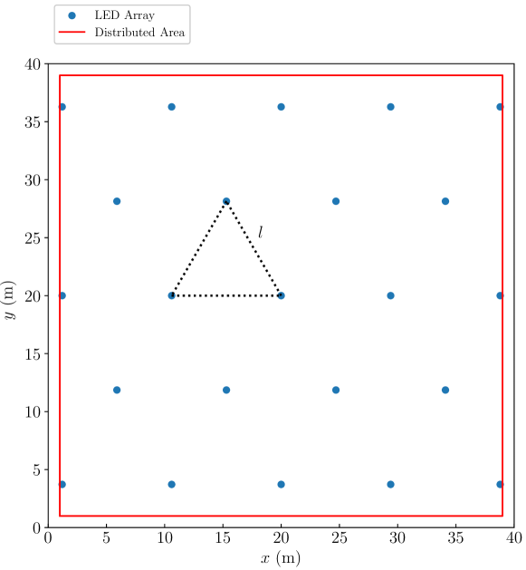
In this work, the parameters of room configuration, LED and PD settings, as well as the body blockage are listed in Table I. Furthermore, in order to reduce the repetitive coverage by different LED units, we consider a new arrangement of LEDs where each LED is placed in the vertexes of equilateral triangles. An illustration of this arrangement is displayed in Fig. 6. The side length of the triangle satisfies the following inequality
| (35) |
Therefore, we have
| (36) |
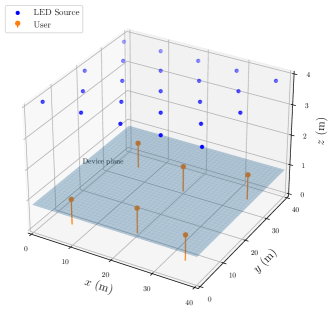
We set the location of the first LED at in the ceiling, and other LEDs are assigned to the blue points (cf. Fig. 6), where the coordinates of any three adjacent LEDs form an equilateral triangle with side length . The geometric coordinates of users are set as in Table II with height m (also illustrated in Fig. 7); Scenario 1 corresponds to the case where all the users are sparsely located in the room (cf. Fig. 7(a)), Scenario 2 corresponds to the case where all the users are closely located in the room, and finally (cf. Fig. 7(b)), Scenario 3 corresponds to the case of a hybrid combination of the two scenarios (cf. Fig. 7(c)). The simulation method is Monte-Carlo with loops.
V-B Transmission Performance
Note that all the following three-dimensional figures in this subsection and beyond are plotted under only the fixed power allocation scheme, since the limit of computational complexity for the numerical optimization solver.
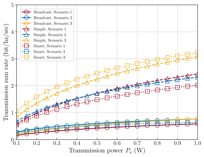
In Fig. 8, we investigate the transmission sum rate of the three aforementioned transmission scenarios with the proposed strategies and fixed power allocation scheme when and are uniformly distributed from 1 m to 39 m (i.e., in the distributed area), which cylinder body may block the light received by the users. From this figure, we can observe that the simple LED linking and smart LED linking strategies outperform the broadcasting strategy. For a comparison of the performance of the simple and smart LED linking strategies, the results depend on how users are distributed. More precisely, in Scenarios 1 and 2, simple LED linking strategy outperforms the smart LED linking strategy. Contrarily, in Scenario 3, the latter strategy outperforms the former one in low transmission power. Apparently, the distribution of the users affects the transmission performance of the system, and we cannot assert which strategy is better. However, we may conclude that in Scenarios 1 and 2, the simple LED linking strategy produces the best transmission performance. For Scenario 3, the simple LED linking strategy has the best transmission performance in the high transmission power regime, whereas the proposed smart LED linking strategy achieves the better transmission sum rate in the low transmission power regime.
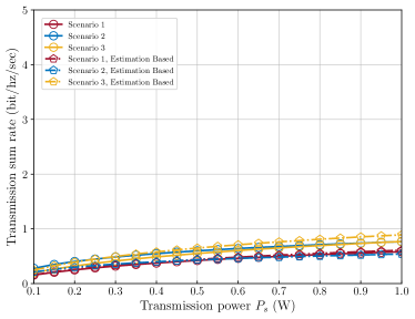
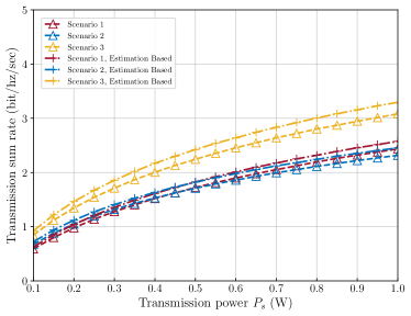
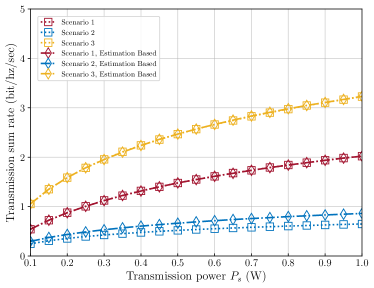
Next, we take a look into the transmission performance of our model with the three strategies under the estimated maximum sum rate-based power allocation scheme. The simulation results are depicted in Fig. 9. From the figure, we can observe that in Fig. 9(a), the transmission performance in the broadcasting strategy for Scenario 2 is greatly low, and this happens due to the fact the estimated maximum sum rate-based power allocation scheme is only based on the expected value of the radiation and azimuth angles, and the power-allocated calculation will generate large errors when the locations of users are concentrated. Besides, the estimated maximum sum rate-based power allocation scheme works well with the simple LED linking strategy as well as the smart LED linking strategy. As shown in Fig. 9(b) and Fig. 9(c), the values of the transmission sum rate for this scheme are basically higher than that for the fixed power allocation scheme based on the sum rate maximization of legitimate users. Furthermore, we can observe that in Fig. 9(c), the estimated maximum sum rate-based power allocation scheme in Scenario 1 and Scenario 3 does not significantly improve due to the fact that the locations of users are sparser than in Scenario 2, i.e., each may only contains one or two users. From these observations, we may conclude that under a realistic VLC system where the light path could be blocked, the newly proposed strategies, i.e., simple and smart LED linking strategies, provide better gain for the transmission sum rate compared to the broadcasting strategy.
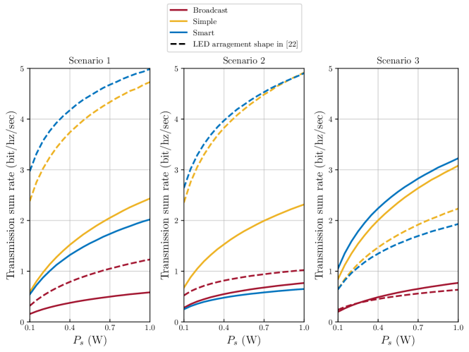
Additionally, in Fig. 10, we compare the transmission sum rate between our proposed LED arrangement and the squared LED arrangement [22] with the same sidelength and total transmission power. From this figure, we observe that in Scenario 3, our proposed scenario outperforms the LED arrangement in [22], but in Scenarios 1 and 2, the transmission sum rate for our proposed arrangement is inferior to that of the arrangement method in [22]. This can be attributed to the fact that the squared LED arrangement increases the overlapping area of two geometrically adjacent LEDs, resulting in an increased illuminance of each device of the user. If the two adjacent different sources transmit the same symbol simultaneously, the transmission performance can be improved. It is worth noting that the transmission performance of the LED arrangements is also significantly influenced by the locations of users, which requires further investigation.
V-C Secrecy Performance
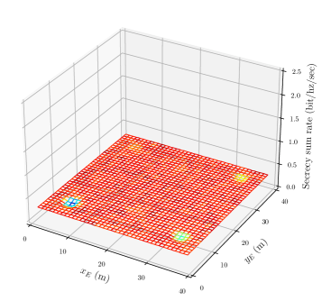
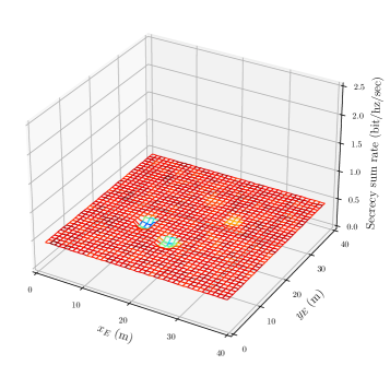
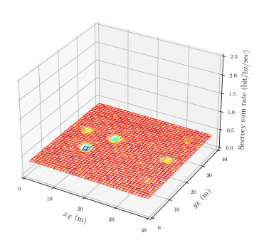
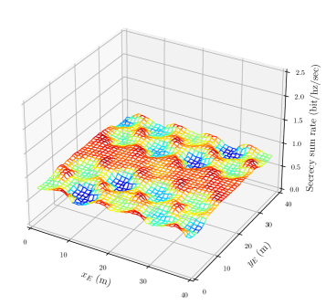
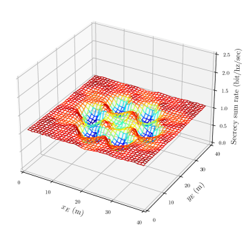
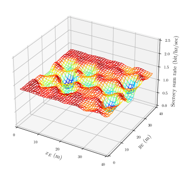
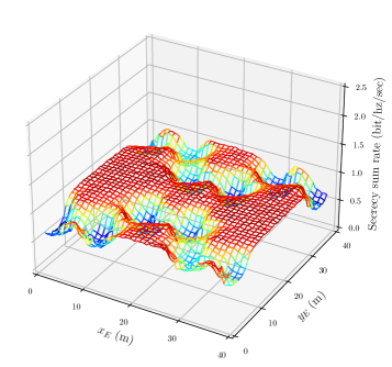
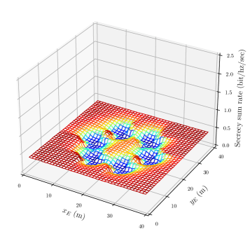
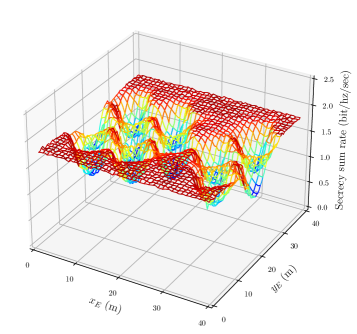
In sequence, the secrecy sum rate and the location of the eavesdropper of our system model are examined with the three transmission strategies under the fixed power allocation scheme. The simulation results for the broadcasting, simple and smart LED linking strategies are shown in Figs. 11, 12, and 13, respectively. From these figures, it is evident that the broadcasting strategy has the lowest secrecy sum rate. The secrecy performances of the simple as well as smart LED linking strategies rely on the distribution of the users. More precisely, for Scenario 2, corresponding to the case where the users are in a small area with high concentration, the simple LED linking strategy gives better secrecy performance than the smart one (c.f., Figs. 12(b) and 13(b)). The reason why it turns out in this way for this case is that the LEDs have the grouping process before transmitting data to users in the smart LED linking strategy in order to bypass signal interference in the overlapping regions. When all the users are concentrated in a narrow space, they may be assigned to a same group. Therefore, only a subset of the entire LEDs is selected to transmit signals to the legitimate users, and the rest makes no contribution to increasing the secrecy sum rate. In different circumstances, if some users are sparsely distributed as in Scenario 3, the smart LED linking strategy provides a higher secrecy sum rate than the simple one, which can easily be seen by contrasting Fig. 12(c) and Fig. 13(c). This is because the eavesdropper cannot wiretap the messages of all the users, and the signal interference from different LEDs is also mitigated, resulting in boosting the secrecy sum rate of VLC systems.
VI Conclusion
In this work, we investigated the transmission and the secrecy performances of the indoor VLC networks for mobile devices equipped with a single PD under NOMA transmission. Specifically, we proposed a geometric body blockage model with a novel LED arrangement and evaluated our proposed model with three different transmission strategies, i.e., broadcasting, simple LED linking, and smart LED linking strategies. As a result, compared to the conventional broadcasting strategy, our proposed simple and smart LED linking strategies provided significant improvements in terms of transmission and secrecy performances in the simulation results.
For future work, the LED arrangement for the different users’ locations needs further investigation, and it may be of significant interest to derive explicit theoretical bounds of the transmission sum rate and the secrecy sum rate for the body blockage model.
Appendix A Proof of Lemma 1
The inner product of a vector on the plane and the normal vector holds that
| (A.1) |
Also, the equation of a straight line that has the directional vector and pass through the point can be described as
| (A.2) |
where is the slope of the line and takes values from the real-valued domain.
References
- [1] N. Chi, Y. Zhou, Y. Wei, and F. Hu, “Visible light communication in 6G: Advances, challenges, and prospects,” IEEE Veh. Technol. Mag., vol. 15, no. 4, pp. 93–102, Dec. 2020.
- [2] A. R. Ndjiongue, H. C. Ferreira, and T. M. N. Ngatched, “Visible light communication (VLC) technology,” in Wiley Encyclopedia Elect. Electron. Eng. John Wiley & Sons, Ltd, 2015, pp. 1 – 15.
- [3] Y. Saito, Y. Kishiyama, A. Benjebbour, T. Nakamura, A. Li, and K. Higuchi, “Non-orthogonal multiple access (NOMA) for cellular future radio access,” in Proc. IEEE 77th Veh. Technol. Conf. (VTC-Spring), Dresden, Germany, Jun. 2013, pp. 1–5.
- [4] Z. Yang, W. Xu, C. Pan, Y. Pan, and M. Chen, “On the optimality of power allocation for NOMA downlinks with individual QoS constraints,” IEEE Commun. Lett., vol. 21, no. 7, pp. 1649–1652, Jul. 2017.
- [5] T. Shen and H. Ochiai, “A UAV-enabled wireless powered sensor network based on NOMA and cooperative relaying with altitude optimization,” IEEE Open J. Commun. Soc., vol. 2, pp. 21–34, 2021.
- [6] A. Akbar, S. Jangsher, and F. A. Bhatti, “NOMA and 5G emerging technologies: A survey on issues and solution techniques,” Comput. Netw., vol. 190, p. 107950, 2021.
- [7] L. Dai, B. Wang, Z. Ding, Z. Wang, S. Chen, and L. Hanzo, “A survey of non-orthogonal multiple access for 5G,” IEEE Commun. Surveys Tuts., vol. 20, no. 3, pp. 2294–2323, 3rd Quart. 2018.
- [8] A. D. Wyner, “The wire-tap channel,” Bell Syst. Tech. J., vol. 54, no. 8, pp. 1355–1387, Oct. 1975.
- [9] M. Bloch, J. Barros, M. R. D. Rodrigues, and S. W. McLaughlin, “Wireless information-theoretic security,” IEEE Trans. Inf. Theory, vol. 54, no. 6, pp. 2515–2534, Jun. 2008.
- [10] Y. Liu, H.-H. Chen, and L. Wang, “Physical layer security for next generation wireless networks: Theories, technologies, and challenges,” IEEE Commun. Surveys Tuts., vol. 19, no. 1, pp. 347–376, 1st Quart. 2017.
- [11] J. M. Hamamreh, H. M. Furqan, and H. Arslan, “Classifications and applications of physical layer security techniques for confidentiality: A comprehensive survey,” IEEE Commun. Surveys Tuts., vol. 21, no. 2, pp. 1773–1828, 2nd Quart. 2019.
- [12] A. Mukherjee, S. A. A. Fakoorian, J. Huang, and A. L. Swindlehurst, “Principles of physical layer security in multiuser wireless networks: A survey,” IEEE Commun. Surveys Tuts., vol. 16, no. 3, pp. 1550–1573, 3rd Quart. 2014.
- [13] A. Mostafa and L. Lampe, “Physical-layer security for MISO visible light communication channels,” IEEE J. Sel. Areas Commun., vol. 33, no. 9, pp. 1806–1818, Sep. 2015.
- [14] X. Liu, Y. Wang, F. Zhou, S. Ma, R. Q. Hu, and D. W. K. Ng, “Beamforming design for secure MISO visible light communication networks with SLIPT,” IEEE Trans. Commun., vol. 68, no. 12, pp. 7795–7809, Dec. 2020.
- [15] S. Cho, G. Chen, and J. P. Coon, “Cooperative beamforming and jamming for secure VLC system in the presence of active and passive eavesdroppers,” IEEE Trans. Green Commun. Netw., vol. 5, no. 4, pp. 1988–1998, Dec. 2021.
- [16] M. A. Arfaoui, A. Ghrayeb, and C. M. Assi, “Secrecy performance of multi-user MISO VLC broadcast channels with confidential messages,” IEEE Trans. Wireless Commun., vol. 17, no. 11, pp. 7789–7800, Nov. 2018.
- [17] T. V. Pham and A. T. Pham, “Energy efficient artificial noise-aided precoding designs for secured visible light communication systems,” IEEE Trans. Wireless Commun., vol. 20, no. 1, pp. 653–666, Jan. 2021.
- [18] F. Wang, C. Liu, Q. Wang, J. Zhang, R. Zhang, L.-L. Yang, and L. Hanzo, “Optical jamming enhances the secrecy performance of the generalized space-shift-keying-aided visible-light downlink,” IEEE Trans. Commun., vol. 66, no. 9, pp. 4087–4102, Sep. 2018.
- [19] Z. Che, J. Fang, Z. L. Jiang, J. Li, S. Zhao, Y. Zhong, and Z. Chen, “A physical-layer secure coding scheme for indoor visible light communication based on polar codes,” IEEE Photon. J., vol. 10, no. 5, pp. 1–13, Oct. 2018.
- [20] G. Pan, J. Ye, and Z. Ding, “On secure VLC systems with spatially random terminals,” IEEE Commun. Lett., vol. 21, no. 3, pp. 492–495, Mar. 2017.
- [21] S. Cho, G. Chen, and J. P. Coon, “Physical layer security in multiuser VLC systems with a randomly located eavesdropper,” in Proc. IEEE Global Commun. Conf. (GLOBECOM), Waikoloa, HI, USA, Dec. 2019, pp. 1–6.
- [22] X. Zhang, Q. Gao, C. Gong, and Z. Xu, “User grouping and power allocation for NOMA visible light communication multi-cell networks,” IEEE Commun. Lett., vol. 21, no. 4, pp. 777–780, Apr. 2017.
- [23] K. Cao, B. Wang, H. Ding, T. Li, J. Tian, and F. Gong, “Secure transmission designs for NOMA systems against internal and external eavesdropping,” IEEE Trans. Inf. Forensics Secur., vol. 15, pp. 2930–2943, 2020.
- [24] K. Cao, B. Wang, H. Ding, T. Li, and F. Gong, “Optimal relay selection for secure NOMA systems under untrusted users,” IEEE Trans. Veh. Technol., vol. 69, no. 2, pp. 1942–1955, Feb. 2020.
- [25] Z. Zhang, C. Zhang, C. Jiang, F. Jia, J. Ge, and F. Gong, “Improving physical layer security for reconfigurable intelligent surface aided NOMA 6G networks,” IEEE Trans. Veh. Technol., vol. 70, no. 5, pp. 4451–4463, May 2021.
- [26] X. Zhao, H. Chen, and J. Sun, “On physical-layer security in multiuser visible light communication systems with non-orthogonal multiple access,” IEEE Access, vol. 6, pp. 34 004–34 017, 2018.
- [27] H. Peng, Z. Wang, S. Han, and Y. Jiang, “Physical layer security for MISO NOMA VLC system under eavesdropper collusion,” IEEE Trans. Veh. Technol., vol. 70, no. 6, pp. 6249–6254, Jun. 2021.
- [28] G. Shi, S. Aboagye, T. M. N. Ngatched, O. A. Dobre, Y. Li, and W. Cheng, “Secure transmission in NOMA-aided multiuser visible light communication broadcasting network with cooperative precoding design,” IEEE Trans. Inf. Forensics Secur., vol. 17, pp. 3123–3138, 2022.
- [29] G. Li, P. Wang, T. Yang, and H. Che, “Secrecy sum-rate enhancement for NOMA-VLC system with pseudo user,” IEEE Commun. Lett., vol. 27, no. 1, pp. 243–247, Jan. 2023.
- [30] T. Shen, V. Yachongka, and H. Ochiai, “Secure NOMA-based indoor VLC networks with body blockage model,” in Proc. IEEE Wireless Commun. Netw. Conf. (WCNC), Glasgow, Scotland, UK, Mar. 2023, to be published.
- [31] M. D. Soltani, A. A. Purwita, Z. Zeng, H. Haas, and M. Safari, “Modeling the random orientation of mobile devices: Measurement, analysis and LiFi use case,” IEEE Trans. Commun., vol. 67, no. 3, pp. 2157–2172, Mar. 2019.
- [32] J. Beysens, Q. Wang, and S. Pollin, “Exploiting blockage in VLC networks through user rotations,” IEEE Open J. Commun. Soc., vol. 1, pp. 1084–1099, 2020.
- [33] A. Goldsmith, Wireless Communications. Cambridge, United Kingdom: Cambridge University Press, 2005.
- [34] T. Komine, S. Haruyama, and M. Nakagawa, “A study of shadowing on indoor visible-light wireless communication utilizing plural white LED lightings,” Wireless Pers. Commun., vol. 34, pp. 211–225, 2005.
- [35] C. Chen and H. Haas, “Performance evaluation of downlink coordinated multipoint joint transmission in LiFi systems,” in Proc. IEEE Global Commun. Conf. Workshop (Globecom Workshop), Singapore, Dec. 2017, pp. 1–6.
- [36] J. M. Kahn and J. R. Barry, “Wireless infrared communications,” Proc. IEEE, vol. 85, no. 2, pp. 265–298, Feb. 1997.
- [37] T. Komine and M. Nakagawa, “Fundamental analysis for visible-light communication system using LED lights,” IEEE Trans. Consum. Electron., vol. 50, no. 1, pp. 100–107, Feb. 2004.
- [38] L. Yin, W. O. Popoola, X. Wu, and H. Haas, “Performance evaluation of non-orthogonal multiple access in visible light communication,” IEEE Trans. Commun., vol. 64, no. 12, pp. 5162–5175, Dec. 2016.
- [39] N. Chi, LED-Based Visible Light Communications, ser. Signals and Communication Technology. Heidelberg, Germany: Springer Berlin, 2018.
- [40] S. Feng, T. Bai, and L. Hanzo, “Joint power allocation for the multi-user NOMA-downlink in a power-line-fed VLC network,” IEEE Trans. Veh. Technol., vol. 68, no. 5, pp. 5185–5190, May 2019.
- [41] T. V. Pham and A. T. Pham, “Secrecy sum-rate of multi-user MISO visible light communication systems with confidential messages,” Optik, vol. 151, pp. 65–76, Dec. 2017.
- [42] C. Chen, W.-D. Zhong, H. Yang, and P. Du, “On the performance of MIMO-NOMA-based visible light communication systems,” IEEE Photon. Technol. Lett., vol. 30, no. 4, pp. 307–310, Feb. 2018.
- [43] S. Boyd and L. Vandenberghe, Convex Optimization. New York, NY, USA: Cambridge University Press, 2004.
- [44] I. Dunning, J. Huchette, and M. Lubin, “JuMP: A modeling language for mathematical optimization,” SIAM Rev., vol. 59, no. 2, pp. 295–320, 2017.
- [45] A. Wächter and L. T. Biegler, “On the implementation of an interior-point filter line-search algorithm for large-scale nonlinear programming,” Math. Programm., vol. 106, no. 1, pp. 25–57, Mar. 2006.