Skyrmion dynamics in moiré magnets
Abstract
We consider a twisted magnetic bilayer subject to the perpendicular electric field. The interplay of induced Dzyaloshinskii - Moriya interaction and spatially varying moiré exchange potential results in complex non-collinear magnetic phases in these structures. We numerically demonstrate the coexistence of intralayer skyrmions and bound interlayer skyrmion pairs and show that they are characterized by distinct dynamics under the action of external in-plane electric field. Specifically we demonstrate the railing behaviour of skyrmions along the domain walls which could find applications in spintronic devices based on van der Waals magnets.
I I. Introduction
Van der Waals (vdW) materials offer unprecedented opportunities to form heterostructures of different monolayers with unique magnetic, transport, and optical properties and enable a powerful toolbox for the bottom-up material engineering [1, 2].
VdW magnets are a relatively novel class of the vdW materials [3, 4]. The first experimental realization of two-dimensional vdW magnets, CrI3 [5] and CrGeTe3 [6] was reported in 2017 and since then the family of 2D magnets is rapidly growing with dozens of new materails appearing each year [7]. Due to the atomic-scale thickness, vdW magnets are highly susceptible to the external perturbations such as external fields [8, 9, 10] and strain [11, 12]. Specifically, perpendicular electric field may induce the Dzyaloshinskii - Moriya interaction (DMI) which leads to the emergence of non-collinear magnetic structures [13] such as helices, individual skyrmions and skyrmion crystals [14]. Moreover, for some vdW materials, their magnetic properties depend crucially on stacking configuration: controlling the stacking angle and relative displacement of individual magnetic monolayers allows for the precise tuning of the interlayer exchange coupling as well as dipole-dipole interaction which results in the emergence of various new magnetic phases in twisted vdW magnets [15, 16, 17, 18, 19, 20, 21].
In twisted magnetic bilayers, the site-dependent interlayer exchange potential, or moiré potential, which is periodic with a period equal to the moiré supercell, defines the spatial scale of the emergent non-collinear phases. At the same time, the chiral interactions such as DMI correspond to an alternative spatial scale which can be tuned by external perpendicular electric fields. It is thus tempting to explore the emergent magnetic phases in twisted magnetic bilayers where both interlayer exchange moiré potential and intralayer DMI are present. Such a competition would lead to a rich phase diagram of such structures, if the strength and characteristic lengthscale of two types of interactions are compatible.
A similar competition of intra- and interlayer interactions takes place in synthetic antiferromagnets [22]. In these structures, two magnetic layers are exchange-coupled through a thin metal non-magnetic spacer due to the Ruderman-Kittel-Kasuya-Yosida (RKKY) interaction of conduction electrons. The magnitude and sign of the interlayer exchange coupling (IEC) depend on the thickness of the nonmagnetic interlayer, which can be chosen in such a way as to ensure antiferromagnetic (AF) exchange. If in one of the magnetic layers there are domains with different directions of magnetization, then in the other layer the same domain structure will be repeated, but with the opposite direction of magnetization.
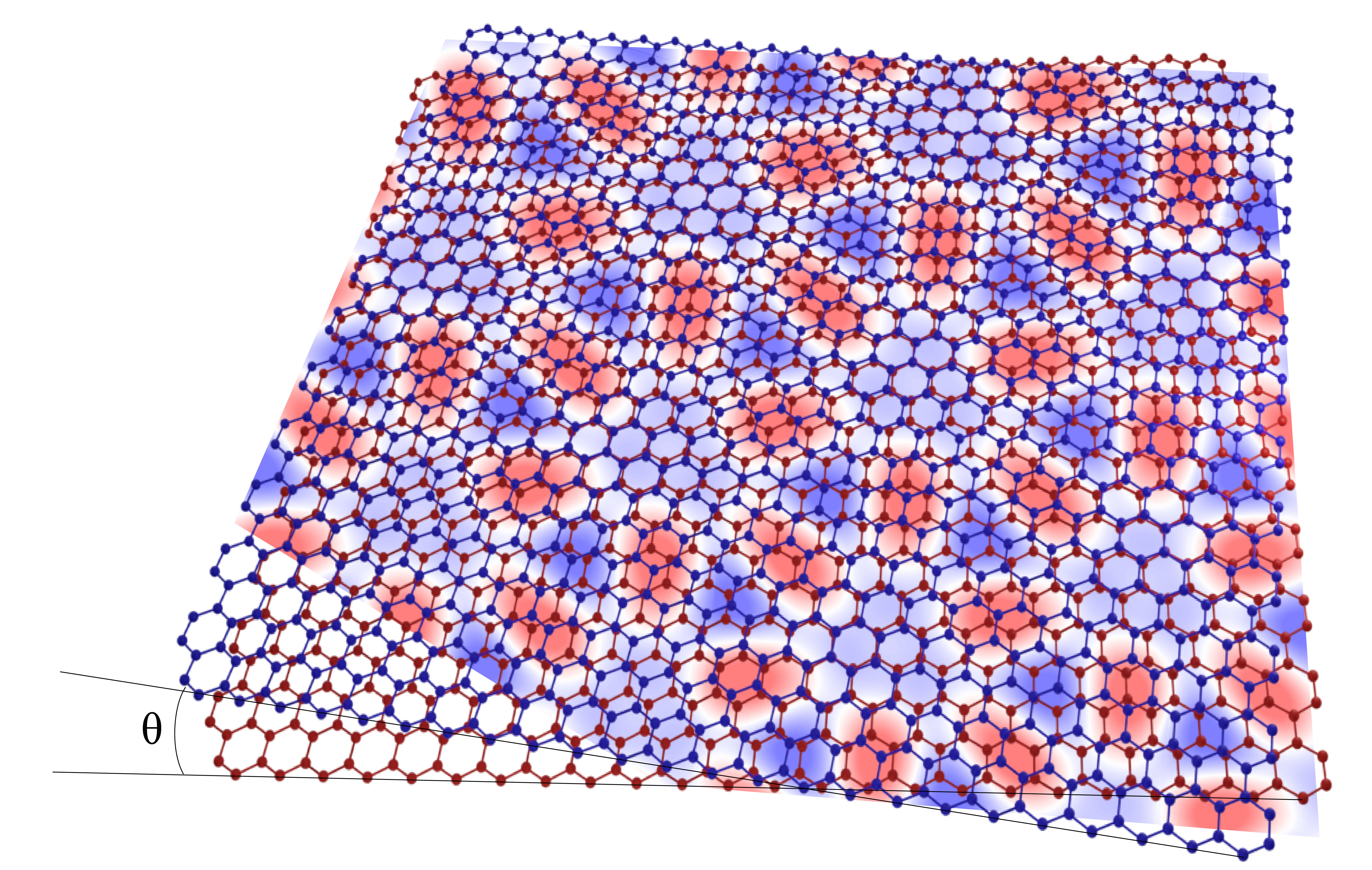
The IEC varies depending on the thickness of the spacer layer. If it is made in the form of a wedge, then the IEC will oscillate with thickness, which will lead to the formation of a domain structure, even if one of the magnetic films is in a single-domain state. Such a smooth change in thickness makes it possible to observe short-range and long-range IEC oscillations in metal magnetic trilayers [23]. If, in the presence of DMI, localized magnetic structures of the skyrmion type are formed in one magnetic layer, then another skyrmion should form in the second layer, which will be in a bound state with the first one [24]. The skyrmions will be coupled ferromagnetically or antiferromagnetically, and this bonding should also vary with the thickness of the nonmagnetic interlayer. The same behavior should be observed in twisted vdW magnetic layers. This article will present the features of the magnetic structure and dynamics of skyrmions in a moire magnet associated with the competition of in-plane and out-of-plane interactions. We consider a structure shown in Fig. 1. A twisted magnetic bilayer is subject to an external electric field inducing intralayer DMI in each layer. The interlayer moiré potential arises due to the spatially dependent IEC. The system models the recently reported experiments with twisted monolayers of [25, 26]. We start from numerical modelling of the magnetic phases supported by this structure. We show that spatially dependent interlayer exchange potential results in complex non-collinear magnetic structures and the formation of Ferromagnetic (FM) and antiferromagnetic domains (AF). Moreover, we show that the system supports several types of intralayer skyrmions as well as bound interlayer skyrmion pairs predicted previously [17]. We then study the skyrmion dynamics using the Landau-Lifsthis-Gilbert (LLG) equation and demonstrate and demonstrate the railing of skyrmions along the domain walls under the action of external in-plane electric field. We give a qualitative explanation of the observed effect using the Thiele equation.
The article is organised as follows: in Section II we define the model and present the results of numerical simulations of the magnetic phases supported by the structure. In Section III we present the results on the dynamics of the skyrmions under the external in-plane electric field. Section IV summarizes the obtained results.
II II. Non collinear magnetic phases in twisted magnetic bilayer
II.1 Model
In our model, we consider two layers of a ferromagnetic material with a hexagonal crystal lattice, rotated relative to each other by a small angle, which determines the shape of the moiré potential. In the ferromagnetic case considered below, the interaction potential is rather difficult to describe analytically, but it can be specified numerically. Moiré period is proportional to , is the lattice period, which is typically about several angstroms. The twist angle we use in our calculations equals to approximately 0.7∘. Profile of moiré potential adopted from [27] is shown in Fig. 2a along with scale bar.
We consider a continuous generalized Heisenberg-type model with the energy
| (1) |
Here and are the unit vectors along the magnetization in layers 1 and 2, respectively, is the magnetic layer thickness. is the exchange stiffness constant. Pairs of nearest atoms in different layers also contribute to the Heisenberg exchange, but the interaction strength depends on the position of atoms and equals , where is a parameter controlling interaction strength.
DMI is turned on in each layer, but there is no antisymmetric exchange interaction between layers. Dzyaloshinskii vectors are parallel to the line connecting interacting spins, the length of the vector determines the DMI density . Anisotropy axis is the same for all points of the system, the anisotropy density corresponds to the easy axis anisotropy. The spin texture generated in a moiré supercell can give rise to an electric polarization associated with such a non-collinear magnetic state due to spin-orbit coupling, resulting in a local ferroelectric order following moiré [28]
When performing numerical calculations, the micromagnetic model is dicretized on a square lattice. A cell of lattice points with free boundary conditions was used. Its size coincided with the cell size in [27], where the moiré potential is taken from.
Micromagnetic parameters are converted into the discrete model parameters
| (2) |
where is the in-plane lattice constant.
In our modeling, we use dimensionless variables, and all parameters in (2) are measured in -units. The easy axis anisotropy, , is used below, which gives an estimate of approximately 22 lattice constants for the thickness of a domain wall in a bulk material without DMI: .
DMI can be varied by changing the external electric field [29], so the system will be considered at different values of the DMI constant. In a bulk material with DMI, the ferromagnetic (FM) state becomes unstable with respect to the transition to the spiral state at . We will use the dimensionless parameter .
II.2 Results
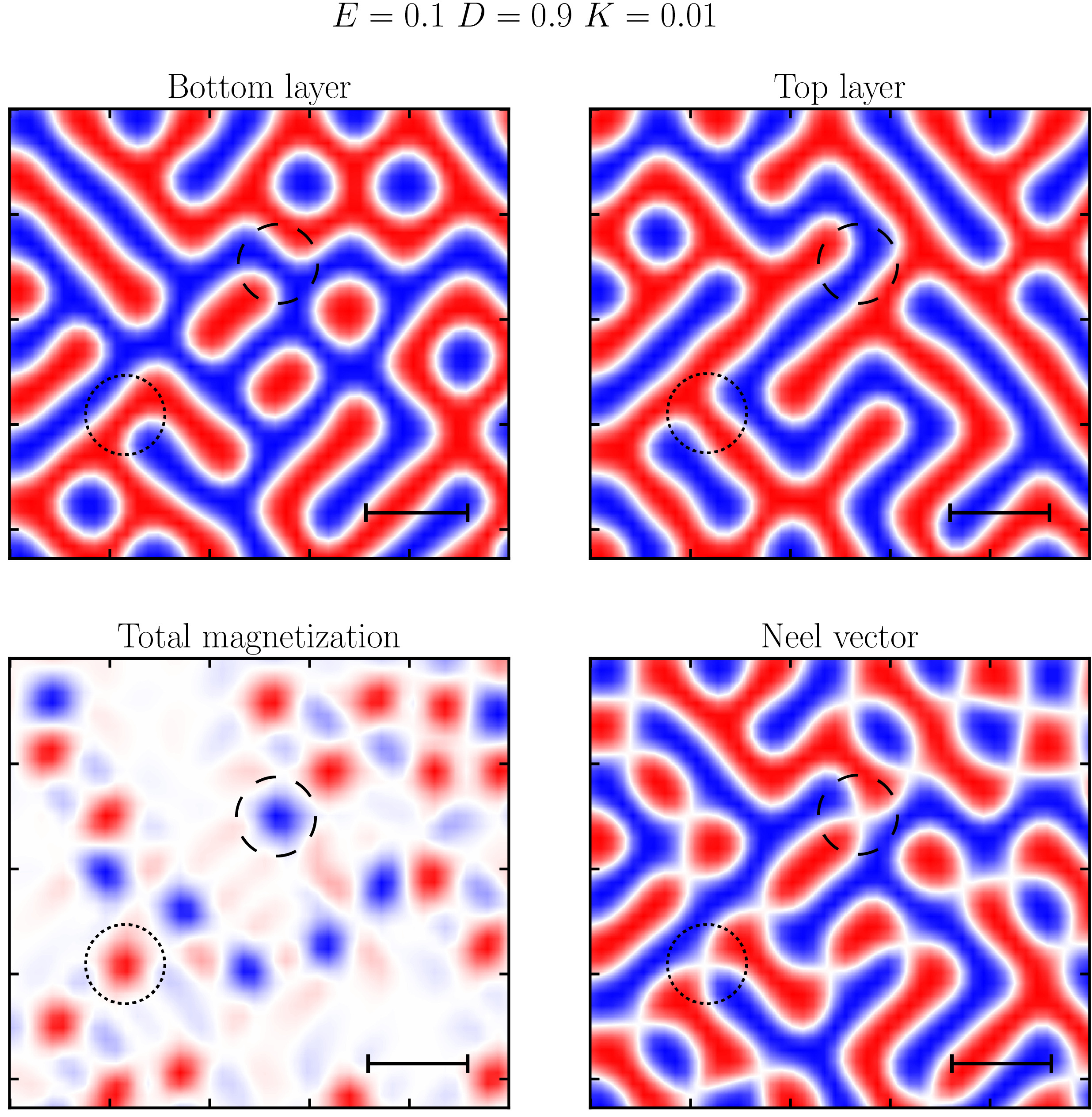
The determination of the magnetic configuration corresponding to the local energy minimum begins from a state with a random distribution of magnetic moment directions. The non-linear conjugate gradient method is used for energy minimization with Hessian matrix evaluated in Cartesian coordinates [30]. The minimization stops when the gradient becomes less than . The system has a large number of metastable states with close energies, and Fig. 2 reproduces the typical examples of locally stable magnetic configurations for different values of the parameter. Fig. 2a shows the spatial configuration of the moiré potential, which defines the regions with FM and AF IEC. The interlayer exchange potential was computed in [27]. (red) and (blue) correspond to the FM and AF exchange, respectively, and the white lines are the FM grain boundaries, where the exchange is close to zero.
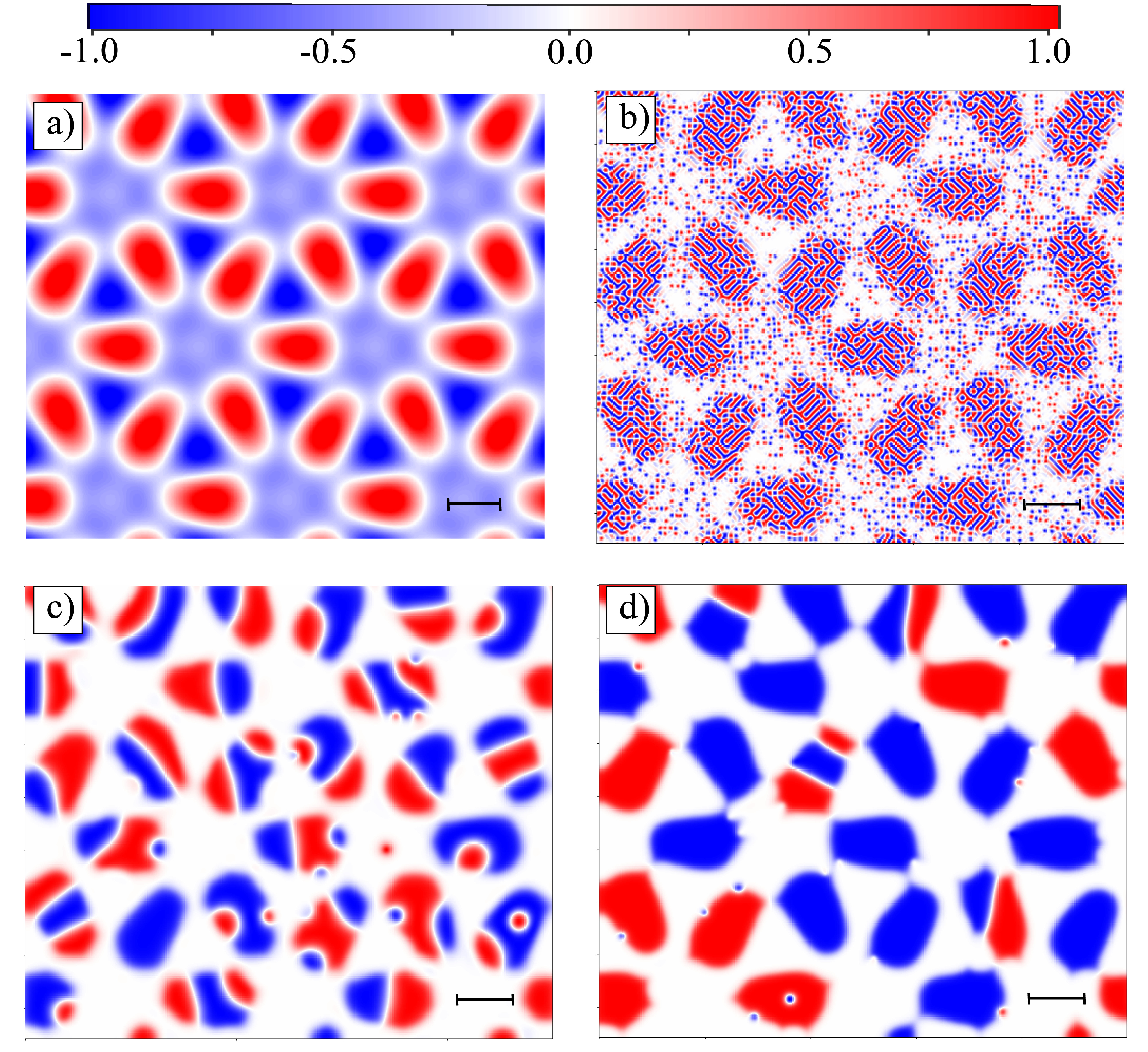
For , the ground state in each layer is a spiral structure of the ”fingerprints” type. In the FM IEC region, the same structure is observed for the total magnetization of both layers, as can be seen from Fig. 2b. In the AF region, the magnetizations of the helical domains are largely compensated, except for the ends of the domains, where point out-of-plane magnetic states appear for total magnetization. These states, however, are not layer-localized structures, and their mobility is very limited, since their movement can only arise as a result of rearrangement of the helical structure in each layer. We provide a more detailed illustration of the formation of these point-like states arising due to the superposition of the domain walls in the two layers in the Supplemental Material.
As effective DMI stregnth decreases, the size of the domains increases. For example, at shown in Fig. 2(c), the domain size is comparable with the moiré grain size. Moreover, the skyrmion states are identified in FM and AFM regions, and at the boundaries between FM and AFM.
For , the observed skyrmions have size much smaller than the regions of a constant IEC sign. Fig. 2d indicates that most of these skyrmions are located at the boundary of the moiré grains, although they also can be found inside the grains. The magnetization profiles for other values of are shown in Supplemental Material illustrating gradual increase of the domain size with the decrease of .
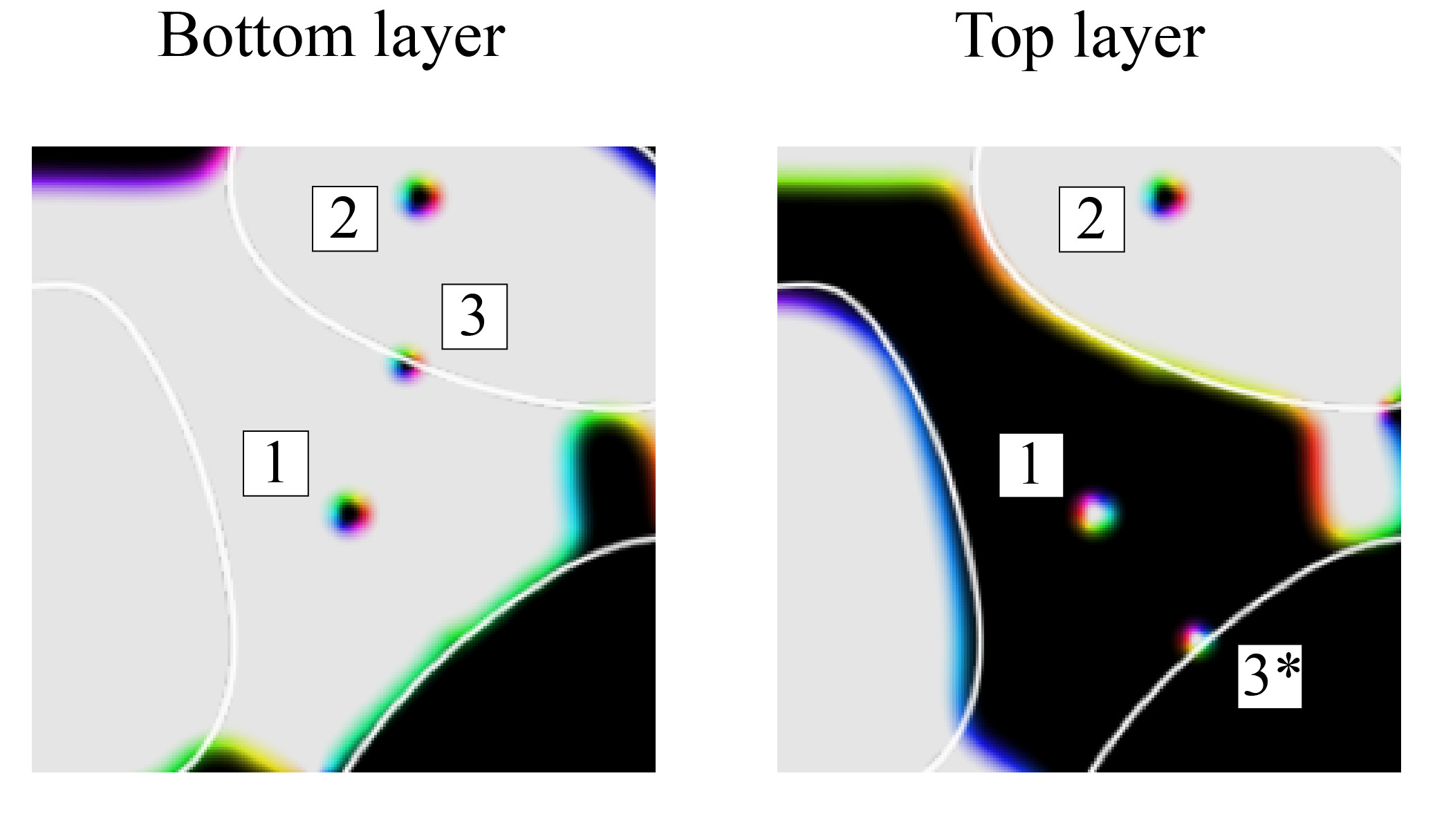
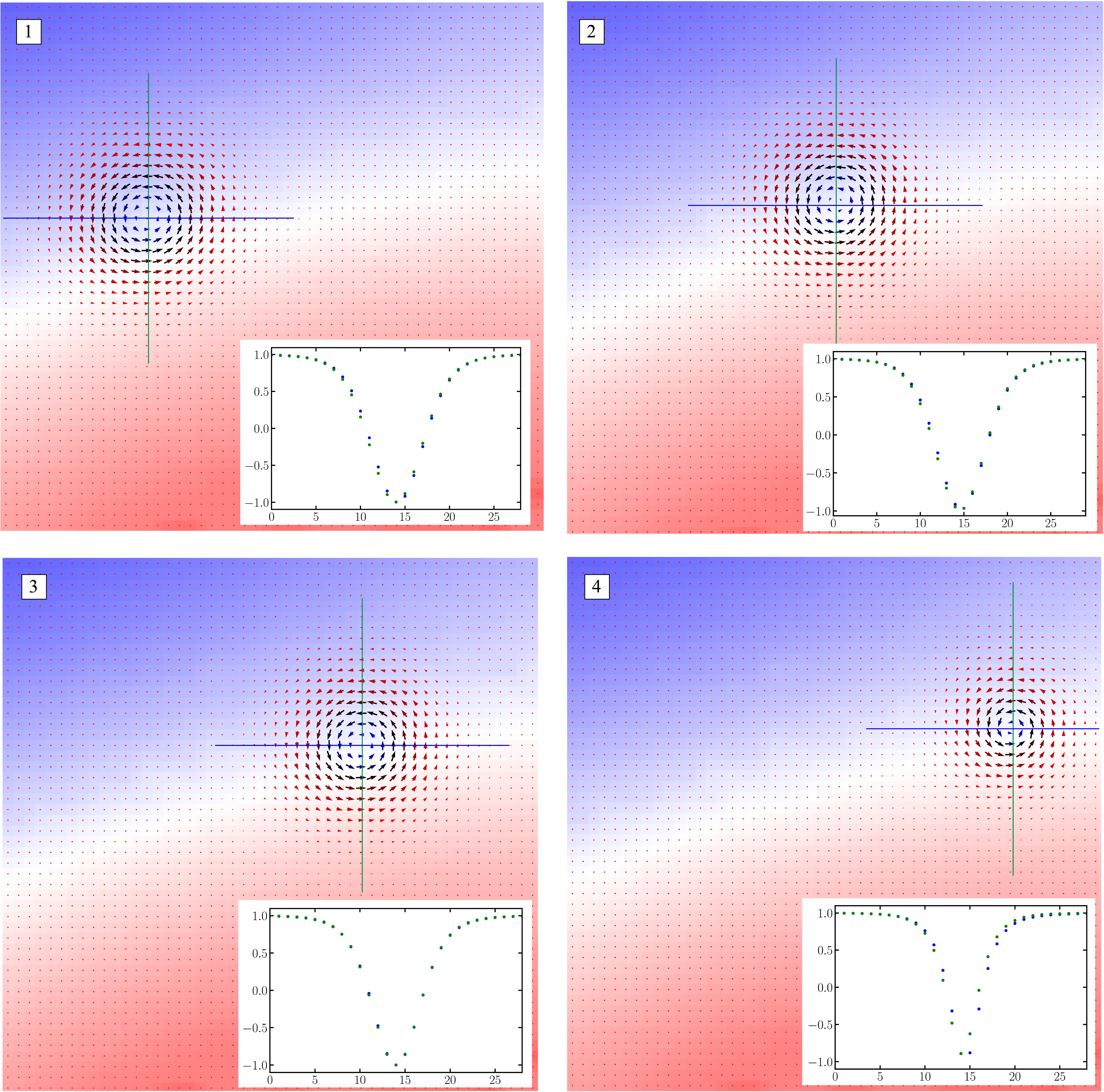
In order to demonstrate different types of skyrmion structures, Fig. 3 shows the configurations in the upper and lower layers of moiré magnet in this case. Pairs of coupled skyrmions can reside both in the AF and FM IEC regions. In the first case (1), the total topological charge of the pair is equal to zero, and in the second (2), to two. Single skyrmions in one layer with a unit topological charge and domain walls in another layer are usually located in the region of zero moiré potential (3).
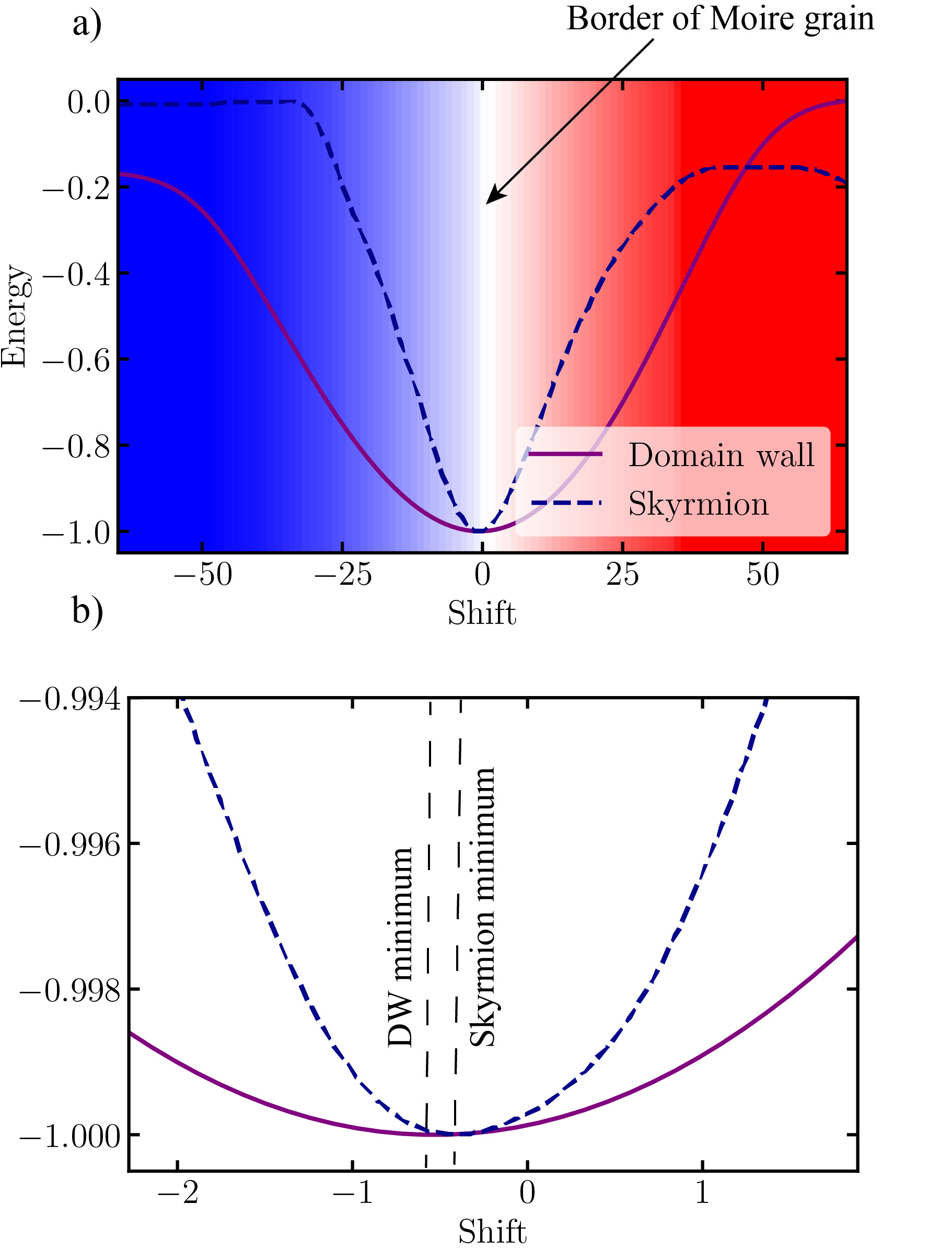
To explain the localization of skyrmions and domain walls near the boundaries of moiré grains, the energies of these structures near the boundaries were calculated. The results are shown in Fig. 4. As a first step, we find the optimal position for the domain wall near zero moiré potential by varying its position along the line perpendicular to the grain boundary and calculating the energy of the system. It can be seen that at a certain position the energy is minimal, so this position is energetically favorable for the domain wall. It is also noticeable that this minimum is slightly offset from the point where , which can be seen on the Figure 4.
The second step is to minimize the energyas function of the position of the skyrmion in the other layer. The wall in one layer remains its position , while the skyrmion in the other layer is translated in the direction perpendicular to the moiré grain boundary. There is also a certain energy minimum here, which does not coincide with the minimum for the domain wall, but is located closer to zero of the moiré potential.
III III. Skyrmion dynamics in twisted magnetic bilayer
In this section we will show that the three described types of skyrmions are characterized by the distinctive dynamics under applied electric field. We perform numerical simulation of the dynamics of the skyrmions using Landau-Lifshitz-Gilbert equation. At the same time, to provide a qualitative explanation of the specific features of the skyrmion dynamics, we employ the Thiele equation, which can be used when one can neglect the modification of the skyrmion internal structure. In the Supplemental Material we provide the results of the numerical simulation confirming that the this approximation is valid. Below we provide a brief derivation of the Thiele equation.
III.1 Thiele equation
The dynamics of the bilayer system is described by the Landau-Lifschitz-Gilbert (LLG) equation:
| (3) |
where is gyromagnetic ratio, is damping parameter and is the effective magnetic field
| (4) |
All the vector fields depend on the layer and the spin coordinates . The term is Slonczewski spin transfer torque (STT) [31]:
| (5) |
where is anti-damping constant associated with STT and
| (6) |
We are interested in the dynamics of the topological solitons assuming their shape is invariant. Denote the position of the soliton in the layer . If the shape is fixed, then are the only varying degrees of freedom. The constrained dynamics is derived by the projecting the velocity to the generators of the translations of the solitons
| (7) |
The projected LLG equation onto the space spanned by the vectors is called Thiele equation. For the multilayer system the Thiele equation becomes:
| (8) |
where is the topological charge of the layer :
| (9) |
and we introduced matrices
| (10) |
The Thiele equation can be solved with respect to . Consider FM pair of solitons assuming their perfect alignment, then the system becomes essentially single layer with thicker layer. Suppose the background phase is isotropic, e.g. FM, then . The Thiele equation in this case is well-known:
| (11) |
The soliton velocity in this case is connected with the current by a linear transform, and the transform commutes with rotations. Therefore the angle between the soliton velocity and the current is constant and is called Hall angle.
If the soliton is invariant under reflections with respect to both coordinate axes (e.g. skyrmion, skyrmionium), then the matrix is proportional to the identity operator , . The Hall angle is given by:
| (12) |
The Hall angle vanishes, if (C1) or (C2) . The value of velocity is proportional to the current:
| (13) |
In the case (C2) the velocity does not depend on the topological charge and on the dissipation constant. In the case , the soliton velocity is given by:
| (14) |
and is determined by ratio of the damping constants.
Thus, the Thiele equation predicts that the skyrmions localized in the AFM domains, will have no Hall angle due to the vanishing of the topological charge, and the sign of the Hall effect for the skyrmions in FM domains depends on the ratio of the Gilbert damping and STT torque . We will further confirm these predictions in the numerical simulations.
For the case, when the skyrmion in one of the layers is in the vicinity of the domain wall in the other layer, one can also employ the Thiele equation. We assume rotational symmetry of skyrmion (in practice the symmetry can be slightly violated due to interaction with the domain wall). For clarity we consider flat grain boundary and straight domain wall, that is the IEC potential and the domain wall texture depend only on coordinate. Energy of the system up to an additive constant is given by:
| (15) |
The magnetization , the current and damping parameters , are assumed equal in both layers. Thiele equation for the system is
| (16) |
First equation in (16) defines two competing forces, acting on a skyrmion on the grain boundary: the first one from potential gradient and the second one from current. Railing behavior of skyrmion is observed for the values of perpendicular current less than some critical value, when the returning force can no longer compensate the action of electric current and the skyrmion leaves the grain boundary.
| (17) |
Here we introduced the parameter :
| (18) |
Fig. 5 demonstrates the equilibrium points and critical current for the case of pinning to the rail.
We now check the predictions of the Thiele equation by numerical simulations via LLG equation. The results of the simulations for the FM and AFM skyrmion pairs are shown in Fig. 6. The simulation was performed by evolving the initial state (labelled ”i.s.” in the figures) for a fixed amount of time and taking the snapshot of the final state. The simulation was performed for three different values of the antidamping constant . First it is seen that, for the AFM skyrmion pair with zero topological charge, the Hall angle vanishes and the skyrmion propagates along the current according to Eq. 12. Moreover, the module of velocity grows linearly with as follows from Eq. 13. For the case of FM skyrmion, the Hall angle is generally finite and depends on the ratio between antidamping constant and Gilbert damping constant .
For the single layer skyrmion localized in the vicinity of the domain wall in the other layer, the LLG simulations are shown in Fig. 7. In the figure, two skyrmions can be identified localized in two two different layers. It can be seen, that for the bottom layer skyrmion, the angle between the current direction and the domain wall is relatively small and thus skryrmion propagates along the domain wall. At the same time, for the top layer skyrmion, the current is almost perpendicular to the domain wall and thus the skyrmion is dragged way from the domain wall and then disappears. This behaviour qualitatively corresponds to the predictions of the Thiele eq. 17. As can be seen, the Thiele equation gives qualitatively correct predictions for the dynamics of the three types of the skyrmions. This is due to the fact that as we show in Supplemental material, the skyrmion profile indeed remains almost unaffected in the course of motion under applied current.
IV Conclusions
We have shown that the interplay of spatially dependent interlayer moiré exchange potential and Dzyaloshinskii-Moriya interaction in van der Waals magnets leads to a rich variety of non-collinear magnetic structures. Specifically, we have identified three distinct families of skyrmions characterized by different topological properties and kinetics under applied in-plane current. Of particular interest are the skyrmions pinned to the grain boundary of the moiré potential. Our numerical calculations predict the railing of these skyrmions along the grain boundary under applied current and we have provided an analytical description of this effect using the Thiele equation. This behaviour is quite general for the two-layer structures with spatially varying interlayer exchange potential and we thus anticipate, that it may be observed in different vdW moiré magnetic bilayers. Railing of skyrmions in vdW magnets opens routes towards novel applications of these heterostructures in spintronics.
V Acknowledgements
The study was supported by the Russian Science Foundation grant N 22-22-00632, https://rscf.ru/project/22-22-00632/.
Appendix A Non-collinear magnetic phases in twisted magnetic bilayer
Fig. 8 provides the evolution of non-collinear phases, stabilized in moiré magnets for different values of . The dimensionless parameter .
More detailed consideration of magnetization for = 10 is given on Fig. 9. The structure obtained in that case is the so-called ”fingerprint” pattern. The small points that manifest in the regions characterized by antiferromagnetic exchange coupling are subjected to a detailed investigation. These defects emerge at the intersections of domains (”fingers”), as visually exemplified in the figure.
Appendix B Thiele equation
To discover the applicability of the Thiele equation in our analysis, we examine the deformation of the skyrmion profile, as depicted in Fig.10. Notably, the skyrmion profile remains predominantly unchanged and retains its symmetry while moving along the domain wall. However, once the skyrmion starts leaving the boundary and begins to collapse, deformation becomes evident. Based on these observations, we infer that the Thiele equation holds validity during the stable motion of the skyrmion.
Appendix C Critical current condition
Consider the system of equations, obtained for the case of skyrmion and domain wall interaction.
| (19) |
Consider first two equations that relate to the first layer. We focuse on the special case, in which the Hall angle vanishes and the skyrmion tends to move along the current (this regime is provided by the special relation between the parameters: . Following this, the equations get the form:
| (20) |
| (21) |
| (22) |
Condition for the critical current (the value of current when the returning force does not compensate the current any more and the skyrmion leaves the boundary): . Here we introduced the parameter .
| (23) |
References
- Liu et al. [2016] Y. Liu, N. O. Weiss, X. Duan, H.-C. Cheng, Y. Huang, and X. Duan, Van der Waals heterostructures and devices, Nature Reviews Materials 1, 1 (2016).
- Novoselov et al. [2016] K. S. Novoselov, O. A. Mishchenko, O. A. Carvalho, and A. H. Castro Neto, 2d materials and van der Waals heterostructures, Science 353, aac9439 (2016).
- Burch et al. [2018] K. S. Burch, D. Mandrus, and J.-G. Park, Magnetism in two-dimensional van der Waals materials, Nature 563, 47 (2018).
- Blei et al. [2021] M. Blei, J. Lado, Q. Song, D. Dey, O. Erten, V. Pardo, R. Comin, S. Tongay, and A. Botana, Synthesis, engineering, and theory of 2d van der waals magnets, Applied Physics Reviews 8, 021301 (2021).
- Huang et al. [2017] B. Huang, G. Clark, E. Navarro-Moratalla, D. R. Klein, R. Cheng, K. L. Seyler, D. Zhong, E. Schmidgall, M. A. McGuire, D. H. Cobden, et al., Layer-dependent ferromagnetism in a van der Waals crystal down to the monolayer limit, Nature 546, 270 (2017).
- Gong et al. [2017] C. Gong, L. Li, Z. Li, H. Ji, A. Stern, Y. Xia, T. Cao, W. Bao, C. Wang, Y. Wang, et al., Discovery of intrinsic ferromagnetism in two-dimensional van der waals crystals, Nature 546, 265 (2017).
- Yang et al. [2021] S. Yang, T. Zhang, and C. Jiang, van der Waals magnets: material family, detection and modulation of magnetism, and perspective in spintronics, Advanced Science 8, 2002488 (2021).
- Jiang et al. [2018a] S. Jiang, J. Shan, and K. F. Mak, Electric-field switching of two-dimensional van der waals magnets, Nature materials 17, 406 (2018a).
- Polshyn et al. [2020] H. Polshyn, J. Zhu, M. A. Kumar, Y. Zhang, F. Yang, C. L. Tschirhart, M. Serlin, K. Watanabe, T. Taniguchi, A. H. MacDonald, et al., Electrical switching of magnetic order in an orbital chern insulator, Nature 588, 66 (2020).
- Jiang et al. [2018b] S. Jiang, L. Li, Z. Wang, K. F. Mak, and J. Shan, Controlling magnetism in 2d cri3 by electrostatic doping, Nature nanotechnology 13, 549 (2018b).
- Li et al. [2019] T. Li, S. Jiang, N. Sivadas, Z. Wang, Y. Xu, D. Weber, J. E. Goldberger, K. Watanabe, T. Taniguchi, C. J. Fennie, et al., Pressure-controlled interlayer magnetism in atomically thin cri3, Nature materials 18, 1303 (2019).
- Qi et al. [2023] Y. Qi, M. A. Sadi, D. Hu, M. Zheng, Z. Wu, Y. Jiang, and Y. P. Chen, Recent progress in strain engineering on van der waals 2d materials: Tunable electrical, electrochemical, magnetic, and optical properties, Advanced Materials 35, 2205714 (2023).
- Jaeschke-Ubiergo et al. [2021a] R. Jaeschke-Ubiergo, E. S. Morell, and A. S. Nunez, Theory of magnetism in the van der Waals magnet cri 3, Physical Review B 103, 174410 (2021a).
- Behera et al. [2019] A. K. Behera, S. Chowdhury, and S. R. Das, Magnetic skyrmions in atomic thin cri3 monolayer, Applied Physics Letters 114, 232402 (2019).
- Chen et al. [2019] W. Chen, Z. Sun, Z. Wang, L. Gu, X. Xu, S. Wu, and C. Gao, Direct observation of van der Waals stacking–dependent interlayer magnetism, Science 366, 983 (2019).
- Sivadas et al. [2018] N. Sivadas, S. Okamoto, X. Xu, C. J. Fennie, and D. Xiao, Stacking-dependent magnetism in bilayer cri3, Nano letters 18, 7658 (2018).
- Tong et al. [2018] Q. Tong, F. Liu, J. Xiao, and W. Yao, Skyrmions in the moiré of van der waals 2d magnets, Nano letters 18, 7194 (2018).
- Huang et al. [2020] B. Huang, M. A. McGuire, A. F. May, D. Xiao, P. Jarillo-Herrero, and X. Xu, Emergent phenomena and proximity effects in two-dimensional magnets and heterostructures, Nature Materials 19, 1276 (2020).
- Song et al. [2021] T. Song, Q.-C. Sun, E. Anderson, C. Wang, J. Qian, T. Taniguchi, K. Watanabe, M. A. McGuire, R. Stöhr, D. Xiao, et al., Direct visualization of magnetic domains and moiré magnetism in twisted 2d magnets, Science 374, 1140 (2021).
- Xu et al. [2020] C. Xu, J. Feng, S. Prokhorenko, Y. Nahas, H. Xiang, and L. Bellaiche, Topological spin texture in janus monolayers of the chromium trihalides cr (i, x) 3, Physical Review B 101, 060404 (2020).
- Xiao et al. [2021] F. Xiao, K. Chen, and Q. Tong, Magnetization textures in twisted bilayer cr x 3 (x= br, i), Physical Review Research 3, 013027 (2021).
- Duine et al. [2018] R. A. Duine, K. J. Lee, S. S. P. Parkin, and M. D. Stiles, Synthetic antiferromagnetic spintronics, Nature physics 14, 217 (2018).
- Unguris et al. [1991] J. Unguris, E. Celotta, and D. T. Pierce, Observation of two different oscillation periods in the exchange coupling of Fe/Cr/Fe(100), Phys. Rev. Lett. 67, 140 (1991).
- Legrand et al. [2019] W. Legrand, D. Maccariello, F. Ajejas, S. Collin, A. Vecchiola, K. Bouzehouane, N. Reyren, V. Cros, and A. Fert, Room-temperature stabilization of antiferromagnetic skyrmions in synthetic antiferromagnets, Nature Materials 19, 34 (2019).
- Xu et al. [2022] Y. Xu, A. Ray, Y.-T. Shao, S. Jiang, K. Lee, D. Weber, J. E. Goldberger, K. Watanabe, T. Taniguchi, D. A. Muller, et al., Coexisting ferromagnetic–antiferromagnetic state in twisted bilayer cri3, Nature Nanotechnology 17, 143 (2022).
- Wang et al. [2022] Q. H. Wang, A. Bedoya-Pinto, M. Blei, A. H. Dismukes, A. Hamo, S. Jenkins, M. Koperski, Y. Liu, Q.-C. Sun, E. J. Telford, et al., The magnetic genome of two-dimensional van der waals materials, ACS nano 16, 6960 (2022).
- Hejazi et al. [2020] K. Hejazi, Z. X. Luo, and L. Balents, Noncollinear phases in moiré magnets, Proc. Nat. Acad. Sci. 117, 10721 (2020).
- Otero Fumega and Lado [2023] A. Otero Fumega and J. Lado, Moiré-driven multiferroic order in twisted crcl3, crbr3 and cri3 bilayers, 2D Materials (2023).
- Jaeschke-Ubiergo et al. [2021b] R. Jaeschke-Ubiergo, E. Suárez Morell, and A. S. Nunez, Theory of magnetism in the van der Waals magnet , Phys. Rev. B 103, 174410 (2021b).
- Lobanov and Uzdin [2021] I. S. Lobanov and V. M. Uzdin, The lifetime of micron scale topological chiral magnetic states with atomic resolution, Comp. Phys. Comm. 269, 108136 (2021).
- Slonczewski [1989] J. C. Slonczewski, Conductance and exchange coupling of two ferromagnets separated by a tunneling barrier, Phys. Rev. B 39, 6995 (1989).