From Warfighting Needs to Robot Actuation:
A Complete Rapid Integration Swarming Solution
Abstract
Swarm robotics systems have the potential to transform warfighting in urban environments, but until now have not seen large-scale field testing. We present the Rapid Integration Swarming Ecosystem (RISE), a platform for future multi-agent research and deployment. RISE enables rapid integration of third-party swarm tactics and behaviors, which was demonstrated using both physical and simulated swarms. Our physical testbed is composed of more than 250 networked heterogeneous agents and has been extensively tested in mock warfare scenarios at five urban combat training ranges. RISE implements live, virtual, constructive simulation capabilities to allow the use of both virtual and physical agents simultaneously, while our “fluid fidelity” simulation enables adaptive scaling between low and high fidelity simulation levels based on dynamic runtime requirements. Both virtual and physical agents are controlled with a unified gesture-based interface that enables a greater than 150:1 agent-to-operator ratio. Through this interface, we enable efficient swarm-based mission execution. RISE translates mission needs to robot actuation with rapid tactic integration, a reliable testbed, and efficient operation.
1 Introduction
Coordinated, collaborative robotic swarms have the potential to offer transformational societal impacts. For example, swarms are expected to significantly improve disaster response activities such as search and rescue and damage assessment, in addition to providing a communication network and even delivering supplies. Swarming may also benefit industries like agriculture and farming through autonomous operations that reduce cost, save time, and improve precision farming. In our work, we focus on the military application of large-scale swarms through the Defense Advanced Research Projects Agency (DARPA) OFFensive Swarm-Enabled Tactics (OFFSET) program. The employment of a robotic swarm increases a military unit’s span of control from 1:1 (Soldier:Platform) to 1:150+. In this way, a swarm may increase mission effectiveness by several orders of magnitude. Swarming is considered a non-linear dispersed (NLD) operation with a RAND report by \citeAedwards2005swarming positing that swarming is the most aggressive form of NLD and that it will play a central role in future military operations when heavy forces are unavailable.
Advances in low-cost robotics hardware, network solutions, sensing algorithms, and artificial intelligence help bring practical large scale robot swarms closer to reality chung_live-fly_2016. These advancements are typically fragmented across unique and isolated problem domains. However, robot swarming is interdisciplinary, spanning several interrelated fields. Autonomy, distributed perception, logistics, mobile ad hoc networking, and human-swarm teaming chung_live-fly_2016; edwards2000swarming are example domains where advances in one area may have positive compounding effects in another. Consequently, to understand the impact of new capabilities on swarm mission outcomes, one must integrate and evaluate their technologies into a swarming ecosystem. This in itself is problematic as few holistic robotic swarming systems exist for large scale swarm research, development, and deployment, especially those that have been fielded and proven to operate with a sufficient technical readiness. Our technology, the Rapid Integration Swarm Ecosystem (RISE), is one such system that addresses this problem.
More importantly, we address the question: can a multi-robot ecosystem designed for rapid integration and one-to-many control can be fielded, where a single operator commands 150+ autonomous vehicles in tactical maneuvers? Large scale swarms have yet to be deployed outside of simulation, and it remains unclear what software and hardware architecture can support single operator command at this scale. Earlier efforts in this direction have been made by chung_live-fly_2016 and clark_ccast_2021, though they are limited in either scope or scale. For the first time, we demonstrate with RISE that large scale swarm control for offensive tactical operations is possible. Further, in this work we discuss our architecture design choices and the requirements that informed our design, which practitioners can use to guide their own work.
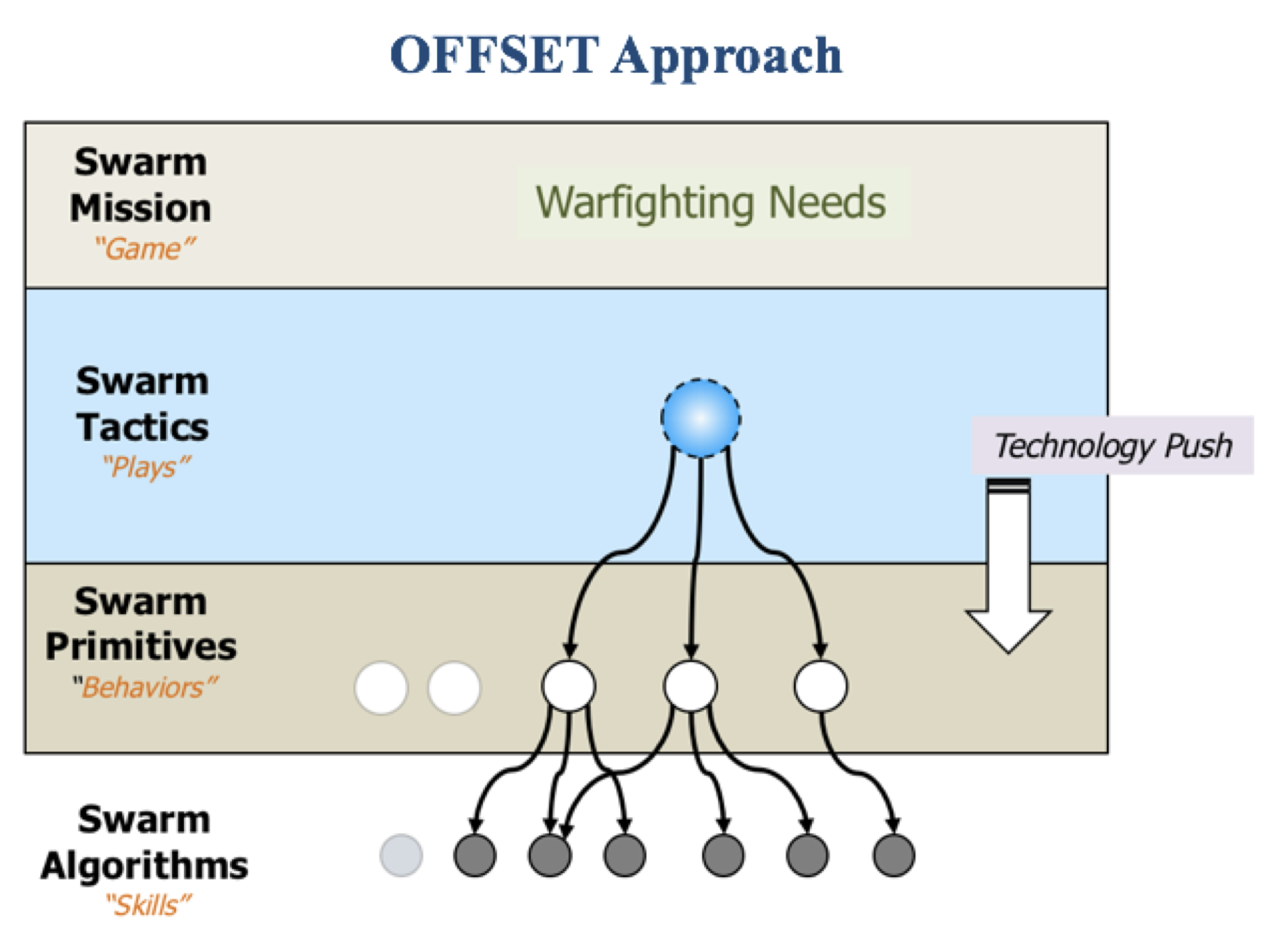
In general, a swarming ecosystem requires a specialized command and control (C2) interface for swarm control. When we designed RISE, it was our goal that our C2 system would enable a single operator to control hundreds of platforms by specifying only high level commands, and enable the operator to build tactics without having to program robot behaviors. To this end, we were inspired by playbook frameworks and decided to leverage the hierarchical swarm framework of Tactics, Primitives, and Algorithms that were established for the DARPA OFFSET program shown in Figure 2. This framework is similar to the work of \citeAmasc, and both drew inspiration from swarm experiments at the Naval Postgraduate School.
The main contribution of this work is RISE111RISE software is maintained by Northrop Grumman Corporation and the US Government. Contact Erin Cherry (erin.cherry@ngc.com) for more information on procedures for gaining access., an end-to-end robot swarming ecosystem that enables rapid development, research, testing, and deployment of large scale heterogeneous robot swarm technologies. The RISE contribution further comprises:
-
1.
A human-swarm team interface that enables a single operator to command large scale swarms,
-
2.
A platform for swarm tactic development and execution that bridges the operator to robots and enables practitioners unfamiliar with robotics software to author tactics, and
-
3.
A lightweight, mobile ad hoc network solution that enables reliable communication at scale between hundreds of agents and other devices.
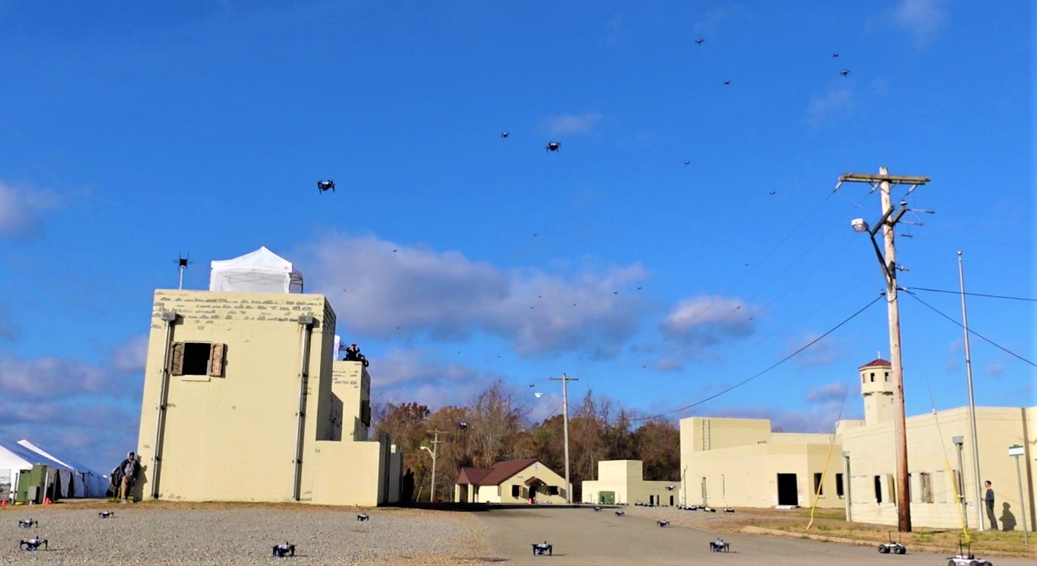
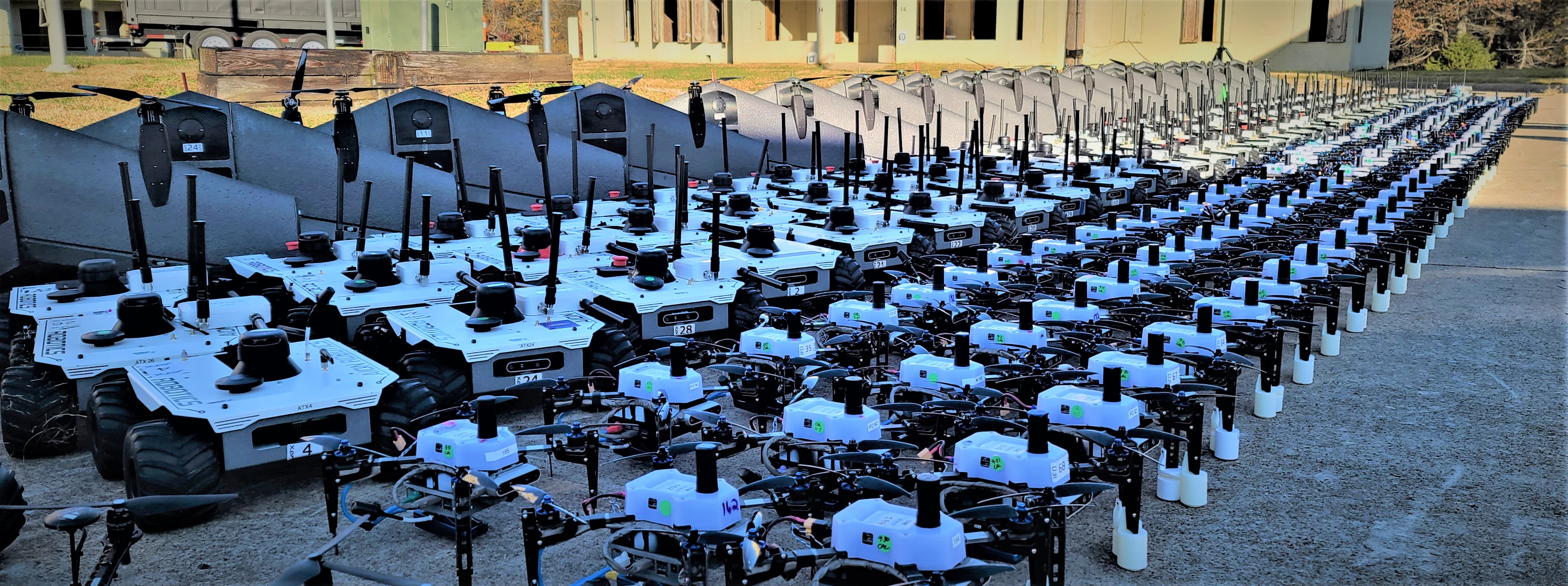
In addition to the RISE software, we customized, configured, and maintained a swarm testbed of over 250 physical, small, unmanned air and ground vehicles. We demonstrated RISE on this swarm testbed at five military ranges over the last four years. The most recent event in November 2021 was the culminating OFFSET swarm field experiment, and we demonstrated one user controlling 174 platforms (84 air and 90 ground).
2 Related Work
In this section, we discuss existing work in several fields relevant to RISE. Where possible, we describe the major papers in those fields. Throughout this section, we also refer the curious reader to existing surveys for further information. We also note that swarms consist of many intelligent “agents,” individual entities which are capable of autonomous sensing, decision-making, and actuation van_der_hoek_multi-agent_2008. We use the words “agent” or “swarm agent” to refer to the robotic hardware platform together with the software which runs upon it. Further, we sometimes make a distinction between simulated agents and physical agents, where the former uses simulated hardware and the latter uses real hardware.
2.1 Multi-Robot Systems
In the literature, “swarm robotics” typically refers to homogeneous systems that have a biological inspiration and which communicate using pheromones or other non-switched networking methods. While RISE is a “swarming ecosystem,” it is also more accurately a “multi-robot system” (MRS) or more generally a “multi-agent system” (MAS). This distinction is highlighted by rizk_cooperative_2019, who perform an extensive and high-quality survey of multi-agent and multi-robot systems. Additional surveys of interest include \citeAdorigo_swarm_2021, which focuses on homogeneous swarm robotics, and \citeAschranz_swarm_2020, which provides a high-level overview of swarm and multi-robot projects. Rather than reiterate the results of these surveys here, we will only highlight especially relevant works. Note that while we refer to RISE as both a “swarm robotics” and a “multi-robot” system in this paper, we limit our discussion to that of multi-robot systems, since they are most similar to RISE.
In particular, we first focus on multi-robot systems which function as testbeds for further research. A survey of multi-robot testbeds is given by \citeAjimenez-gonzalez_testbeds_2013, although several advances have occurred since its publication. Significant early testbeds included the Mobile Emulab johnson_mobile_2006, HoTDeC stubbs_multivehicle_2006, and RAVEN how_real-time_2008. The Mobile Emulab and HoTDeC were characterized by homogeneous robotic platforms and constrained operating environments, only capable of operation in a lab. Both are designed to provide access to remote users who may control the systems’ operations via the internet. In both testbeds, robots are extremely simple with limited localization or sensing capabilities of their own, instead relying on centralized camera systems. Importantly, neither study develops abstract swarm concepts such as tactics or primitives, instead providing only a basic computing platform on each agent without a swarm software framework.
Of these early multi-robot testbeds, perhaps the most similar to RISE is RAVEN, a heterogeneous air and ground swarm testbed designed for experimentation with a variety of multi-robot scenarios. While the software architecture is similar to that of RISE, RAVEN is limited to ten vehicles and may only be used in a lab with some external sensing apparatus. Additionally, RAVEN’s C2 paradigm is mostly focused on direct control of individual vehicles, whereas RISE focuses on command of the swarm as a whole to maximize the agent-to-operator ratio.
In \citeApickem_gritsbot_2015 and later in \citeApickem_robotarium_2017, the authors showcase a multi-robot testbed created by their GRITSBot platforms. More recently, the “ARGroHBotS” testbed was published by \citeAospina_argrohbots_2021 and “Crazyswarm” was published by \citeApreiss_crazyswarm_2017. Again, these testbeds are limited to lab use and have no or limited command and control functionality.
The Swarmanoid project developed a heterogeneous swarm or multi-robot system consisting of both unmanned aerial vehicles (UAVs) and unmanned ground vehicles (UGVs) dorigo_swarmanoid_2013. As with other projects, the Swarmanoid authors do not clearly define a framework for swarm tactics and overall behavior, and do not clearly state how additional behaviors may be integrated with their system. However, they provide an advanced multi-robot simulator, ARGoS, which remains in use for multi-agent research to this day dorigo_swarmanoid_2013.
The COMRADE multi-robot system is an advanced multi-robot system intended for clearing mines and explosive devices in conflict zones. COMRADE provides multi-robot search, data fusion, task allocation, and a basic C2 interface, and is designed for real-world use dasgupta_comrade_2015. However, the authors do not expand on the concept of tactics or other abstractions for the design of new swarm behaviors; rather, the system is single-purpose. Additionally, the C2 system is extremely rudimentary, providing only the barest of controls to direct individual agents and apparently lacking the ability to manually command the swarm as a whole by issuing new tasks for allocation.
The RUTA heterogeneous swarm abukhalil_coordinating_2016 is developed primarily for research on dynamic task allocation. However, it takes a similar approach to robotic hardware abstraction as RISE, allowing for extreme heterogeneity. Some definition of the different layers of software execution for swarm behaviors is provided, with RUTA’s “actions” being similar to RISE’s agent-level “primitives” or “algorithms” abukhalil_coordinating_2016. However, the swarm is small and not designed for scale with only five robots. Additionally, the system primarily focuses on task allocation and does not include any concepts related to C2.
More recently, \citeAchamanbaz_swarm-enabling_2017 developed a hardware and software package to enable simple integration of robotic platforms into a multi-robot system. It consists of computing and networking hardware which can be integrated with existing platforms, along with a software library to enable creation of new behaviors using those platforms. This platform is tested on two separate swarm systems. However, the authors do not differentiate between different layers of the behavior stack (tactics, primitives, and algorithms) and do not consider any human-computer interaction factors. In fact, the authors make no mention of any type of user interface or control.
A significant multi-robot system is presented by \citeAchung_live-fly_2016, in which fifty UAVs are simultaneously controlled by a team of two. This work may be thought of as a direct predecessor of OFFSET with the same program manager, Dr. Timothy Chung, with similar goals of enabling multi-robot systems to perform complex coordinated actions while under the control of a minimal number of operators. This work is expanded upon by \citeAgros_multi-swarm_2018, in which two of the UAV swarms created by \citeAchung_live-fly_2016 battle for air dominance. RISE expands upon this work with a far greater number of agents, innovative new C2 concepts, a software architecture designed for integration of new tactics and behaviors, the introduction of heterogeneity, and more.
Recently, a number of tools which ease the development of multi-robot systems have been created. One such tool is ROS2swarm, a hardware and package for the Robot Operating System 2 framework (ROS 2) that can be retrofitted to existing platforms. ROS2swarm provides multi-robot programming capabilities using a similar breakdown of swarm software to our tactics, primitives, and algorithms concept kaiser_ros2swarm_2022. However, ROS2swarm does not enable dynamic transitions between tactics. In other words, the agents may only perform one tactic in a single execution run without a complete reboot of the robot software. ROS2swarm also does not provide any command and control capabilities, unlike RISE. Additionally, ROS2swarm currently uses a centralized network (access point-based) topology, while RISE uses a decentralized topology. While the ROS2swarm is tested with just six agents, we are quite certain that the ROS2swarm system is actually incapable of supporting large numbers of agents (150+), given its use of ROS 2’s built-in networking mechanism. RISE replaces ROS 2’s default networking mechanism with a custom solution for inter-agent communication. See Section 4.3 for further details on RISE’s networking solutions.
An alternate platform, SwarmUS, is provided by \citeAvillemure_swarmus_2022, which includes both a hardware retrofit board and a software package, similar to \citeAkaiser_ros2swarm_2022. This provides necessary services for a multi-robot system such as communication, coordination, and localization. An Android-based C2 interface is also provided, but appears to be rudimentary and is not designed for control of a large-scale swarm by a single operator. In fact, SwarmUS was tested on no more than six robots, as opposed to RISE’s hundreds villemure_swarmus_2022. Importantly though, SwarmUS appears to focus primarily on hardware design, whereas RISE primarily focuses on software design. Thus, the two are difficult to compare further.
RISE is contemporaneous with “CCAST”, developed by our counterparts on the DARPA OFFSET program clark_ccast_2021. As CCAST and RISE solve the same problems and are designed for the same program and experiment scenarios, most of their capabilities are quite similar. However, RISE differs from CCAST in its use a decentralized mesh network for communication, as opposed to CCAST’s access point approach. Additionally, RISE makes use of innovative common gesture commands for easy cross-platform use on laptops, touchscreen devices, and virtual & augmented reality, whereas CCAST uses a point-and-click virtual reality interface. CCAST shares the behavior decomposition of tactics, primitives, and algorithms with RISE.
2.2 Robotic Platforms
Since RISE is a complex system of software which may be used with a variety of hardware platforms (see LABEL:fig:robots), we do not elaborate on prior hardware platforms used for swarm robotics or multi-agent research. Surveys on this area may be found in the literature, such as the one by \citeAschranz_swarm_2020 which lists a number of platforms.
2.3 Swarm Networking
Swarm robotics systems in the literature may be broadly divided between those which use biologically-inspired “pheromone” systems, directional communications such as in \citeAkornienkoInfraredComms, and nondirectional radio-based networks. We will focus here on undirected digital radio-based networks, since we believe that the former methods are so different from our approach as to be nearly incomparable.
Three types of radio network architecture are commonly used: central access points, local wireless broadcasts, and mobile ad hoc networks (MANETs). In traditional wireless networks, agents communicate only with fixed infrastructure (known as an access point). Direct agent-to-agent communication is impossible. Instead, agents must first send data to the access point, which then retransmits the data to the destination agent. By contrast, a MANET allows both traditional agent-to-infrastructure communication and direct agent-to-agent communication hoebeke2004overview.
A central access point approach is used by the CCAST system clark_ccast_2021. The authors of that study found that agent connection to the access point became a major concern because agents were unable to communicate directly with their neighbors, thus increasing collision risk. For two neighboring agents to communicate, each needed an active connection to the access point, something not always possible in urban environments. This approach is also found in \citeAstubbs_multivehicle_2006 and numerous other implementations.
Local wireless broadcast architectures are more common. While they often do not require a central access point, these architectures typically do not support relaying of data, distinguishing them from true “MANETs” by the definition in \citeAhoebeke2004overview. In \citeAcentibots, an agent-to-agent local wireless broadcast is used. A similar system is employed by \citeArubensteinThousandBots, where data is not relayed to agents beyond reception range of the transmitting agent, and only “local” communication with nearby neighbors is possible. Similar methods are implemented in \citeAcaprariAliceBot,dorigo_swarmanoid_2013.
cianciEPuck implement a true MANET. Their approach makes use of the ZigBee mesh protocol. ZigBee is also used to implement a MANET by \citeAfernandesZigbee, \citeAjevticRoboBees, and \citeAzahugiLibot, among others. By far, the ZigBee system is the most popular MANET implementation in the literature. A MANET solution by Rajant Corporation is also used with success in an unmanned aerial vehicle swarm application by \citeAengebraaten2019uav, and in a mine-exploration swarm in \citeAdarpaSubT.
2.4 Simulation
As with any robotic development, simulation is a critical tool, but especially so with multi-agent and swarm systems. Simulations dealing with multiple agents vary widely in implementation, but even more so in their ability to translate from simulation to actual hardware. A large majority of swarm simulations typically consist of custom-built simulation environments to do evaluation on particular algorithms hamer2010simulation. While this is appropriate for those particular evaluations, a setup of this nature would not suffice for a rapid integration swarming ecosystem such as RISE. Given this, we focused more on simulation environments that emphasize one-to-one translation to hardware, such as Gazebo Aguero-2015-VRC. We leveraged lessons learned and best practices of simulations of this nature and then focused on making the necessary adjustments to maintain the real world translation while still reaching the necessary number of simulated agents (250+ per the OFFSET program). In LABEL:sec:Simulation, we go into more detail of this approach and additional acknowledgments of other relevant simulations.
2.5 Human-Swarm Interface
Human-swarm interaction specifically and human-robot interaction generally is an active area of research that includes interface design, control, communications, autonomy, and human factors such as situation awareness and cognition load, among others drew2021multi; chen2021human; kolling2015human; hocraffer2017meta. However, in this subsection we focus on work that enables a one-to-many operator control over an offensive swarm, beginning with command complexity and ending with user interface customization.
Command complexity draws parallels with computational complexity in that total effort is bound by the number of decisions and actions an operator must take to complete a task lewis2006teamwork. When robots work independently, effort grows linearly with the number of robots an operator must command, . Conversely, tasks requiring careful coordination between robotics may result in superlinear complexity . Lewis provides by way of example the coordination of two unmanned vehicles pushing on the corners of a box, where the operator oscillates between each robot to move and straighten the box.
Although command complexity enables practitioners to compare the bounded efficiency of different command strategies, fan-out is another useful measure proposed by \citeAolsen2003metrics that one uses to estimate how many homogeneous robots an operator can effectively operate at one time. Fan-out is defined mathematically as , where neglect time is the expected duration of time a robot can be ignored without degrading beyond a minimum performance threshold, and interaction time is the duration of time required to interact with a robot crandall2005validating. Intuitively, the more a robot can do without requiring operator attention and the faster an operator can set up commands, the more total robots an operator can command without falling below a required level of performance. Prior work has shown an operator can command between eight and twelve robots simultaneously wang2009search, depending on a variety of factors. This implies we must move away from direct robot control toward a higher level of abstraction in order to support large scale offensive swarming.
One solution is to increase swarm autonomy mi2013human. Command complexities moving toward order can be achieved in part through the use of planners lewis2013human. Consider that without path planners and obstacle avoidance, it has been found that operators are unable to supervise more than a few UAVs cummings2007predicting. Delegating certain tasks to an autonomy can further improve command complexity and fan-out. For example, \citeAmclurkin2006speaking designed a swarm interface inspired by the poplar real-time strategy games WarCraft and StarCraft. These games enable a player to control individual units, groups of units, or an entire army with simple high level commands such as mine, build, and attack. By distributing a single command to multiple robots, amortized interaction time can be significantly reduced and fan-out improved. Similarly, command complexity becomes sublinear when the operator can command multiple robots with only a single command when he or she is able to rely on the underlying automation. Another example called Playbook miller2000tasking; calhoun2018human provides operators with a library of play templates that the operator can modify and which automation adapts to the situation. Playbook is analogous to a sports team’s playbook, where a leader selects a play that the team executes, and several studies have shown the benefits of templated plays.
We adopt a similar approach to these delegation strategies. In RISE, an operator controls the swarm by using mission level tactic commands that appropriate resources and coordinate the actions of multiple robots. An operator may combine tactics to form a course of action (COA) and modify the plan in real time as the situation changes. During mission planning with human warfighters, commanders communicate tactics through COA diagrams that include tactical control measures to establish responsibility and constrain operations that prevent units from interfering with each other united2015field. This concept is easily extended to swarm command using a sketch and gesture based interface to simulate the natural use of pen and paper. \citeAhammond2010sketch, for example, developed a system for free-hand COA diagram sketch recognition with support for military symbology, achieving high accuracy on 485 symbols.
One issue is that COA diagrams are drawn with standardized military symbology, such as those defined by MIL-STD 2525D army2020field. However, RISE swarm tactics and control measures are constantly evolving and for some time will remain unstandardized. For this reason, practitioners who develop new tactics and control measures require rapid interface integration for development, test, and deployment. This can be achieved through gesture customization using rapid prototyping gesture recognizers jackknife. In this way, we are able to expand our tactics library without requiring direct interface developer support or cluttering the interface, all while supporting a one-to-many low command complexity relationship.
3 Background
3.1 On the Decomposition of Warfighting Needs into Robot Actuation
We illustrate the hierarchical relationship between warfighting needs and robotics algorithms as envisioned by DARPA’s OFFSET program in Figure 2. This decomposition leads to a multilevel classification system that maps warfighting into operator, swarm, robot, and hardware component objectives. Each level corresponds to a unique perspective, world view, and development approach. Although we did not intentionally design RISE’s architecture to reflect this hierarchy, it nevertheless organically evolved into a distributed system comprising four components that directly correlate to the hierarchy: a user interface for translating warfighting needs into tactics, a system for tactics development, a platform composition of primitives, and a framework for algorithm design and integration. In further detail, top-down:
-
•
Warfighting Needs: Based on mission objectives, warfighters generate mission plans that evolve through time and drive swarm command. One must therefore translate mission plans into swarm tactics that satisfy mission objectives. However, one must maintain situation awareness (SA) in order to adapt the mission plan to new information. This requires that the swarm reports relevant information to the command and control (C2) team. Our C2 interface for mission planning, tactics execution, and SA is described in Section 5.
-
•
Tactics: Tactics encompass the ordered arrangement and maneuver of forces on or near the battlefield tactics. Whereas primitives are robot-centric, tactics herein are swarm-centric, being software that organizes and employs agents to achieve mission level objectives. An “overhead scan” is an example tactic that partitions an aerial space into regions, each of which requires reconnaissance. Overhead scan may then utilize multiple agents by issuing multiple move-to primitives to complete its objective. Like primitives, one may construct tactics hierarchically. A “breach” tactic may incorporate tactics for persistent surveillance and building entry, followed by exploration and securement. In RISE, we enable tactics development through a Python-based software application called PyC2 (see Section 6).
-
•
Primitives: Primitives are software components that utilize algorithms to achieve robot-centric objectives. One example primitive is the “move-to” behavior, where an agent travels to a specific battlefield location while avoiding threats. Move-to employs algorithms for localization, path planning, and obstacle avoidance. In parallel, a second continuously running primitive enables the agent to maintain situation awareness via sensor input analysis and communication with other agents. Although move-to works to avoid threats, a third primitive may recognize an immediate inescapable danger, preempt move-to, and engage the threat. Primitives are therefore compositional and hierarchical. Our interface for primitive development and integration is described in LABEL:sec:rise_primitives.
-
•
Algorithms: Algorithms are the software components that interface with hardware by analyzing sensor input and driving actuator output. Example algorithms include computer vision techniques like YOLO yolov1 that recognize objects embedded in video frame data, localization techniques that perform dead-reckoning from continuous inertial measurement unit (IMU) data brossard2020ai, and actuation of motor control systems from velocity commands. Single algorithms enable platform capabilities; they are also known as skills. Our interface for algorithm development and integration is described in LABEL:sec:rise_algorithms.
3.2 The Human-Swarm Team
Over the course of five large-scale field experiments and several intermediate integration tests, we self organized our human team into five disparate roles that we refer to as the swarm commander, swarm operator, swarm health engineer, field operations officer, and field support personnel. Each role not only accounts for one aspect of running a successful mission, but also correlates with the amount of responsibility we found one person could handle without overloading the individual. We envision that these roles will further evolve as robotics technologies, swarming, and RISE continue to mature, and that they can be adopted to a variety of organizational structures. The roles in detail are as follows:
-
•
Swarm Commander: A commander leads the C2 team by defining mission objectives, converting those objectives into a mission plan, modifying the plan as the mission progresses, and coordinating with C2 team members. A commander interacts with C2 software to maintain situation awareness, but does not directly command the swarm. In this way, the swarm commander’s interaction with C2 software correlates with how a platoon or company leader would use the tool.
-
•
Swarm Operator: An operator interfaces with the swarm by converting the mission plan into swarm tactics using C2 software. An operator is also responsible for maintaining situation awareness, reporting intelligence information to the commander, and making tactical recommendations based on evolving circumstances and swarm capabilities. The operator may also request support from the swarm health engineer to command individual agents or investigate error conditions. While there are currently no military occupational specialties (MOS) for swarm operators, we expect this role will map to several MOS categories, including the 15W, which is a single UAV operator.
-
•
Swarm Health Engineer: A health engineer monitors the communications network as well as individual agents’ health. An engineer is a technician who is able to diagnose and remotely resolve robotics issues. In an operational setting, this role could fit into a variety of engineering MOS specialties.
-
•
Field Operations Officer: The field operations officer is responsible for logistics involving agent deployment, recovery, physical maintenance, field personnel coordination, and operational safety. An operations officer coordinates with the commander and may lead a small ground team of field support personnel. The field operations officer role is an artifact of the logistical construct of the field experiment events, the swarm hardware utilized (e.g., limited battery life), and safety requirements for system testing at scale.
-
•
Field Support: Field support personnel report to the field operations officer and provide the logistical power needed to deploy and maintain the swarm. Given the known limitation of hardware and the need for sustained operations over extended periods of time, this team provides the means to recover vehicles and prepare them for redeployment. We expect that as the technology continues to mature, the need for this role will subside.
In line with DARPA OFFSET program objectives, we employed a heterogeneous swarm of low-cost ground and aerial vehicles. For aerial operations, we leveraged quadcopter platforms and vertical take-off and landing (VTOL) fixed wing aircraft. Each platform type offers unique operational benefits, but also comes with its own limitations. Further details on the platforms we leverage and their tradeoffs are presented in LABEL:sec:fx6swarm.
3.3 Live, Virtual, & Constructive
Time, logistics, and cost constraints prohibit frequent testing of single agent and large-scale swarm solutions. To support rapid development and integration, it is therefore critical that engineers are able to iterate their software designs without having access to physical hardware. Simulation facilitates this goal, but only when the simulation and deployment environments are uniform. Otherwise, engineers lose time supporting multiple related but incompatible interfaces. In other words, software developed in simulation should transition directly to the real world without concern over what is real or virtual. For this reason, we take care to ensure our software is abstracted from an underlying reality, such that user interface features, tactics, and primitives are unaware of the underlying platform’s true nature. We further discuss our Live, Virtual, & Constructive (LVC) approach in LABEL:sec:Simulation.
4 The Rapid Integration Swarming Ecosystem (RISE)
4.1 Requirements
requirement Req. 1 \BODY
The design of our swarming architecture is informed by program requirements as well as our experiences as an OFFSET systems integrator. We present some high-level system requirements below:
Capable of one-to-many (150+) operator-to-agent ratio for control of swarm agents.
In reviewing prior systems, we found that operators were unable to effectively command more than a handful of individual platforms (see Section 2.5). Thus, one of our primary goals for RISE is to enable the operation of hundreds of vehicles simultaneously by a single operator. This necessitates the concept of “swarm operation” as opposed to individual agent operation, whereby the operator directs the swarm as a single unit rather than providing commands to individual agents.
Capable of supporting 250 networked agents.
As part of the DARPA OFFSET program, RISE is required to support at least 250 networked agents in simultaneous operation, although this number was not reached in any official field experiments (see LABEL:sec:field_experimentation due to logistical (not technical) limitations. This requirement necessitated the creation of advanced networking protocols and techniques (see Section 4.3).
Capable of operation in a real-world, uncertain environment.
The RISE swarm must be capable of operating in real-world, non-lab environments. To enable intelligent decisions and effective C2 in the field, this requires agent-level sensing and autonomy along with robust networking and communication.
Tactics development abstracted from robotics software.
We found that many involved in swarm-based research are not roboticists, especially those focused on tactics development. These individuals prefer to view robots as entities capable of autonomous navigation through the environment with which they have only occasional interactions. Their concerns primarily lie in the organization and coordination of independent agents that serve an operational objective, such as to intelligently acquire and maintain situation awareness. In other words, tactical engineers typically take an exocentric world view, solving problems at a level of abstraction above the robot. An architecture serving tactical engineering needs will then separate tactics from behaviors, enabling the engineer to focus on converting a mission level objective into a set of robot commands. Therefore, RISE must provide such an abstraction to allow these engineers to easily develop new tactics.
Robotic development for primitives and algorithms to support tactic creation.
While tactic development was abstracted in such a way that robotics expertise is not needed, there is still the need for capable robotic platforms. Most off-the-shelf platforms do not come setup with the capabilities required to perform the tactics that were created within RISE. The tactics have a dependency upon the robots being capable of autonomous navigation through the environment and environmental interactions. These dependencies drive the development described in LABEL:sec:rise_primitives and LABEL:sec:rise_algorithms.
Flexible swarm command interface for tactical coordination.
Tactics vary in complexity and oversight. While a tactical engineer may not be concerned with the underlying task management system, support for allocating robot cohorts, initiating direct and indirect command, synchronizing command execution, canceling outstanding tasks, and receiving command status is required.
Interface for exposing new tactics, tactic parameters, and tactical control measures.
To facilitate rapid development and because tactical engineers often do not use end-user interface software, an engineer must be able to easily define a new tactic description, means of invocation, associated parameters, and required tactical control measures, which are then immediately available to the operator.
Support for virtual hardware in real experimentation.
While the RISE software is hardware-agnostic, research programs such as DARPA OFFSET often have funding limitations and use off-the-shelf platforms (see LABEL:fig:robots) with limited capabilities. Thus, not all desired experiment scenarios may be feasible with the physical hardware. For this reason, RISE is required to provide support for simultaneous operation of simulated and physical agents.
Low fidelity simulation for rapid development.
While high-fidelity simulations are useful for development of robotic behaviors and for testing, we found that tactic developers often did not have the computing resources necessary for a full simulation. Therefore, one of RISE’s earliest requirements is to enable low-fidelity simulation that can be run on a basic laptop computer. This allows rapid iteration on tactics development by our third-party collaborators (see LABEL:sec:integrations).
Simulation for robotic development and evaluation.
While the low fidelity simulation is primarily utilized for tactic development, there is still a need for a simulation that supports primitive and algorithm development. Without a simulation of this nature, robotic development is tedious and always requires on platform testing. Therefore the simulation must support both mock sensor feeds and actual hardware endpoints.
4.2 The RISE Architecture
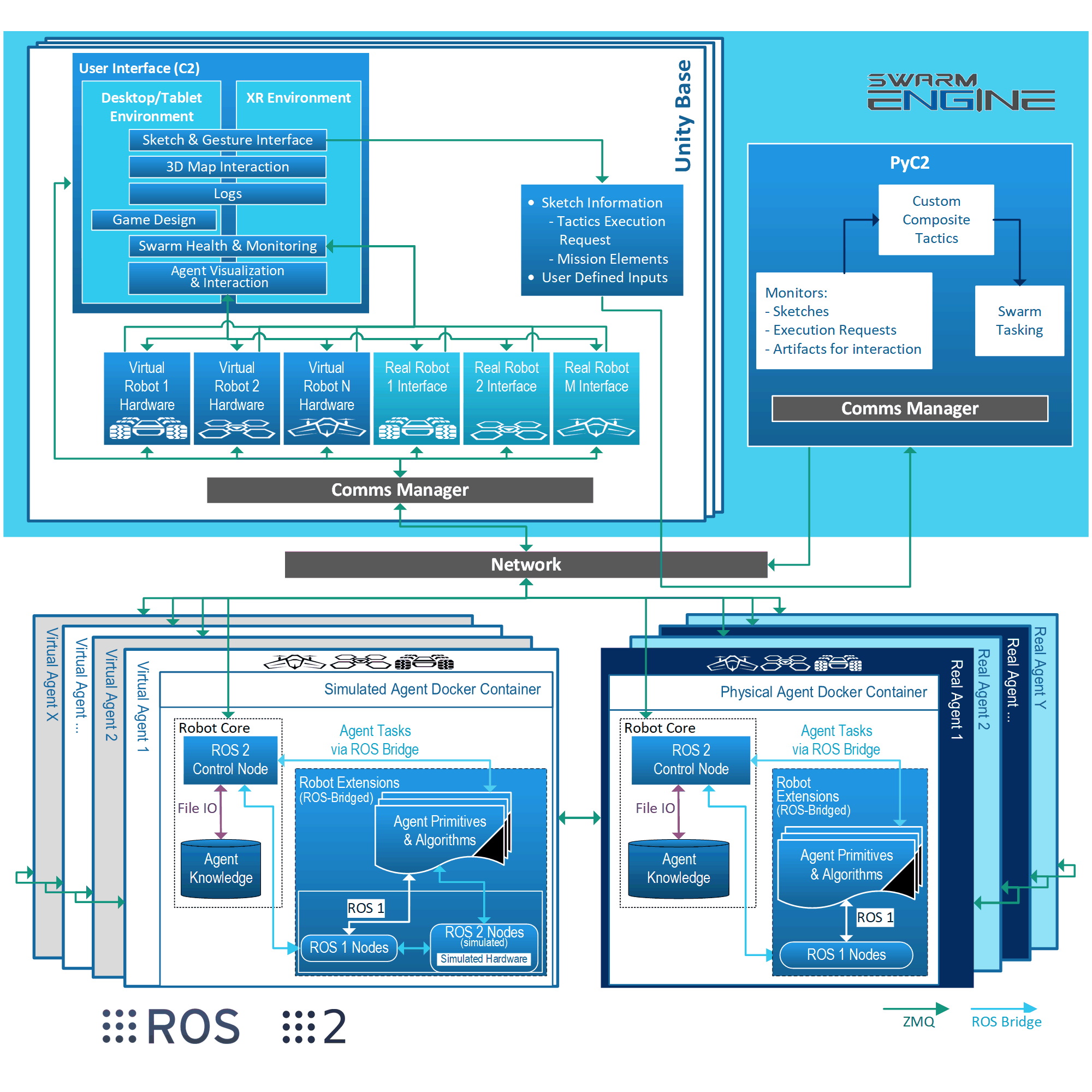
The RISE architecture presented in Figure 3 conforms with the decomposition of warfighting needs into robot actuation, as discussed in Figure 2. One of the major components is called Swarm Engine™ and houses the command and control solution, which includes C2 and PyC2. The former (C2; referred to as “Unity Base” in Figure 3) implements our user interface software for environment visualization, situation awareness, and sketch-based swarm command. We implemented C2 using the Unity game engine222https://unity.com because of its cross-platform compatibility; ability to support advanced desktop, VR, and AR interactions; and built-in simulation support, in addition to having a large active community. PyC2 is a Python-based software application designed for rapid tactics development. It comprises a number of tools designed to assist developers with writing tactics that interact with sketch input, query the environment, and generate robot primitive commands. PyC2 implements a task allocation system, and provides low fidelity simulation support so that engineers can iterate tactic designs without having to run robot software, as specified by Requirement 4.1. We chose to build PyC2 in Python because of the language’s ease of use, extensive library, and wide use, thus fulfilling Requirement 4.1.
Agent software is divided into “Robot Core” and “Robot Extensions” modules, both encapsulated by a Docker container. Together, these components fulfill Requirement 4.1. Robot Core is a platform-agnostic compilation of ROS/ROS 2 nodes that handle key functions for task bidding, task execution, health monitoring, swarm communication, and situational reasoning and reporting. All external communication from agent to agent or agent to swarm is also facilitated through the Robot Core system. This creates a layer of abstraction that enables any agent running the Robot Core software stack to become part of the swarm. Robot Core interacts with agents via their given Robot Extensions codebase. The Robot Extensions codebase contains all the ROS nodes responsible for sensor or hardware interaction, as well as onboard agent algorithms (see LABEL:sec:rise_algorithms). Interaction between Robot Core and Robot Extensions is facilitated by standard ROS messaging, using a bidirectional ROS 1 to ROS 2 bridge333https://index.ros.org/p/ros1_bridge/ when appropriate.
Note that in the architecture diagram (Figure 3), there are two variants of the agent software listed—one representing the software running on a physical agent and the other representing a simulated agent. The only differences between the two are the Docker images used and the ROS 1 sensor data sources. The simulation environment, which is the same Swarm Engine environment used for commanding real platforms, generates sensor information in place of real sensors (see LABEL:sec:level3). This distinct abstraction of sensor feeds works to facilitate simulation to hardware translation and fulfill Requirement 4.1. All aspects of the agent software are contained within Docker containers for easy deployment and simulation testing. We also make use of Ansible444https://www.ansible.com/ for fleet management and deployment using this Docker based system (see LABEL:sec:fx6swarm).
4.2.1 ROS
ROS 555https://ros.org/ is a key component of the RISE architecture. Everything was developed with ROS in mind for ease of integration and development. The agent software consists of a mixture of ROS and ROS 2 nodes. Due to a lack of hardware driver support in ROS 2 at development time, the Robot Core modules use ROS 2 and the Robot Extensions modules currently use ROS, although Robot Extensions may be upgraded to ROS 2 at a later date when all required drivers are available in ROS 2. All inter- and intra-agent messages are transmitted using either native ROS 1/2 messages using standard ROS networking middleware or ROS 2 messages using a custom ZeroMQ middleware (see Section 4.3). All communication between components of Swarm Engine and varying instances of the Unity environment uses ROS messaging. The simulation environment broadcasts ROS sensor messages to integrate with the agent software for development and testing. ROS messaging is how all algorithms and primitives communicate, and is used at every level of the system, from tactic tasking down to agent-level actuation. ROS’s MAVLink/MAVROS package handles all sensor and actuator interaction on each agent. During the course of development for RISE, several releases of ROS and ROS 2 were utilized, but the program currently uses ROS Melodic and ROS 2 Eloquent.
4.3 Swarm Networking
This section describes the network used to enable communication amongst agents and between agents and the operators. We start by providing a summary of early prototypes and challenges and then describe the final topology and protocols.
4.3.1 Initial Prototypes
In the early stages of RISE development, extremely simple off-the-shelf mechanisms were used for swarm networking. Due to availability of components, RISE initially used standard 802.11 Wi-Fi with all agents connected to centralized access points. However, field experiments (see LABEL:sec:field_experimentation) quickly exposed the downsides of this approach. Operators needed to pre-position the communication infrastructure before mission execution could begin. This was a difficult process requiring careful site surveys to ensure maximum coverage and establishment of a power supply and network backhaul link at the chosen access point location. Obviously, such preparatory work was deemed impractical for real-world tactical exercises. Additionally, even with site surveys and careful access point placement, the dense concrete urban environment used for field experiments (see LABEL:sec:field_experimentation) yielded large “dead zones” in which agents were unable to communicate with the pre-installed access points.
To alleviate these issues, and with the addition of further funding, we conducted an evaluation of commercial off-the-shelf networking solutions and purchased equipment for a mobile ad hoc network (MANET) from Rajant Corporation. See Section 4.3.2 for more information on the benefits of this approach.
However, after switching to a MANET architecture, we encountered further problems. While initially we had been using the default ROS 2 messaging mechanism for inter-agent communications, we found that this did not scale well to more than a few tens of agents when using a MANET. ROS 2 messaging is based on the Data Distribution Service (DDS). Thanks to the MANET’s shared medium (2.4 GHz and 5 GHz radio frequency bands), large numbers of radios attempting to transmit simultaneously caused significant data loss and retransmission, rendering the network practically unusable. We worked extensively with our DDS vendor’s engineers to resolve this problem, but were still unable to operate hundreds of agents simultaneously. At that point, we began implementation of our own protocol solution for inter-agent communications. See Section 4.3.4 for more information.
4.3.2 Mobile Ad hoc Network
One of the critical challenges in fielding a multi-agent robotic system is in the design of a robust communication network. While several architectures were initially considered, we employed a mobile ad hoc network (MANET), commonly referred to as a mesh network, in order to facilitate all communication between agents and all non-emergency communication with C2 operators.
We selected the MANET architecture for a variety of reasons, which we list below:
-
•
Urban environments typically comprise structures of varying materials and geometric complexity that obstruct radio communications, preventing access-point-based networks from effectively communicating with agents inside of buildings or agents in-between structures. We found this to be especially true in the environments used for our field testing (see LABEL:sec:field_experimentation). A MANET alleviates this problem by allowing other agents in the vicinity to act as network relays, a capability that RISE’s tactics exploit. For example, see the building clearing capability developed by SoarTech in LABEL:sec:soartech_integration.
-
•
By using a MANET, we make optional the pre-positioning of network equipment inside the operational area, a task that is required when using networks designed around central access-points.
-
•
A MANET architecture eliminates any single-points-of-failure in the system, allowing agents to continue operation even if one or more of the ground radios fail. The agents may communicate directly with any other devices in the network without routing messages through any centralized infrastructure.
-
•
The MANET architecture allows for easy swarm deployment, a critical capability when operating large-scale swarm systems. Agents do not need to be reconfigured for different deployment strategies, and the ground infrastructure can be changed on-the-fly without any network reconfiguration.
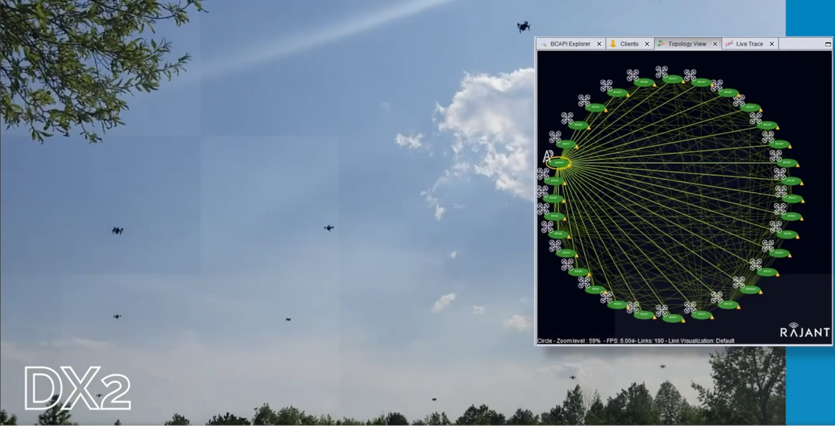
For these reasons, we chose a commercial off-the-shelf MANET solution from Rajant Corporation, utilizing a number of different radios from their product line in our system. Air vehicles are equipped with Rajant DX2 or DX4-series radios, while ground vehicles are equipped with the ES1. The ME4 and Peregrine-series radios are used for ground/base communications, connecting the operators’ Ethernet network to the MANET. The mounting of these radios are shown in Figure 4. All radios operate on the 2.4 GHz band. Except for the DX2s, all radios also utilize a second channel on the 5 GHz band. Rajant software manages the use of these bands to allow for efficient transmission with many radios in close vicinity.
4.3.3 Network Overview
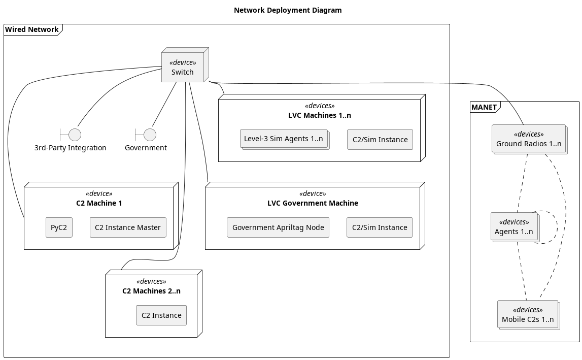
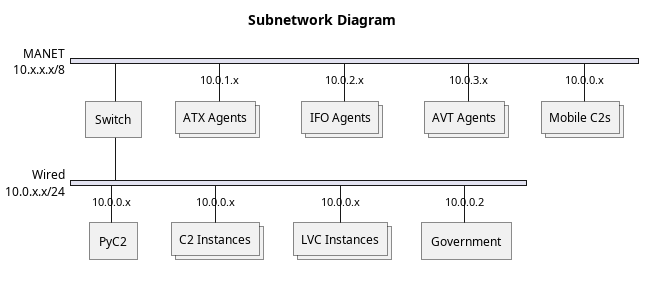
While the MANET described above is critical for agent communication, it cannot handle the high volumes of data necessary for LVC sensor simulation (see LABEL:sec:Simulation). For this reason, we add a 1000BASE-T Ethernet network, connected to the MANET via a switch. This Ethernet network serves multiple LVC simulation machines, plus various C2 computers, and facilitates connections with 3rd-party ground systems (see LABEL:sec:integrations). The overall network is shown in Figure 5.
4.3.4 Network and Transport Protocols
Initially, we attempted to use ROS 2’s built-in network stack, which is based on the Data Distribution Service (DDS). However, we quickly found that DDS was not suitable for our large-scale MANET due to DDS’s discovery phase overhead dds. We instead implemented a custom solution using ZeroMQ zmq as a socket library to allow for reliable multicast communication between all networked systems.
We use the Internet Protocol (IP) rfc791 as the basis of our swarm network. Every agent has an IP address and is joined to one or more IP multicast groups using the Internet Group Management Protocol (IGMP). In multicast, a device must only transmit one message, which is addressed to a group and will be received by all members of the group rfc1112. This is advantageous in our architecture, since it reduces the amount of air time that a vehicle’s radio must use for message transmission. Transmitting a unicast message once for every agent that must receive it (often 200+) requires a significantly larger amount of airtime than transmitting a single multicast message. In a swarm with potentially hundreds of radios in proximity, this is a critical consideration. We take advantage of Rajant’s “Tactical Multicast” feature to prevent multicast messages from “echoing” around the network. This feature allows multicast messages to reach all vehicles with minimal retransmission throughout the MANET rajantMulticastPatent.
We divide our messages into two transport classes: reliable and unreliable. Both use the IP network protocol, but have different transport protocols. For unreliable messages, standard User Datagram Protocol (UDP) datagrams are employed to transport messages. This protocol ensures message correctness, but does not guarantee delivery or reception order rfc768. Such a protocol is ideal in a dense transmitter environment, since it minimizes transmissions and does not waste air time by attempting to retransmit unimportant data.
For messages that require delivery guarantees, we use the Pragmatic General Multicast (PGM) protocol. PGM uses negative acknowledgments to enable retransmission of lost or corrupted messages. That is, each device maintains a sequence number, which is periodically transmitted in a heartbeat message (SPM packet) to other devices. This allows receiving devices to recognize message loss and request retransmission of those messages using a negative acknowledgment (NAK) rfc3208. We changed several PGM parameters from their default values to allow for more efficient use of our limited network resources. Information on these parameter changes is included in LABEL:app:network.
4.3.5 Application Protocols
As all agents in the system use ROS 2 for their high-level logic and control, integration of the network stack with ROS 2 was a crucial requirement. We created a “Communication Handler” ROS 2 node and package for this purpose. The node accepts a user-specified list of ROS 2 topics (see Section 4.2.1) to be transmitted to or received from the network. The application protocol was designed to be straightforward and easy to implement. We first encode the topic name as a 32-bit value using the DJB2 hash algorithm djb2. Then, we use the MessagePack library to encode each field of the message using MessagePack’s efficient encoding scheme msgPack. Each field of the ROS 2 message is automatically decoded and then encoded as a MessagePack field, and the whole message is packed into a structure described by Figure 6. The message is then transmitted using the ZeroMQ library over one of the transport mechanisms described above.
[bitwidth=1.1em]32
\bitheader0-31
{rightwordgroup}Header
\bitbox3232-bit topic name hash
{rightwordgroup}Payload
\wordbox[lr]1MessagePack-encoded payload
\wordbox[blr]1
To receive a message, the reverse occurs. The message is received by ZeroMQ, the topic hash compared against a dictionary of known topics (and the message dropped if unknown), and then each field is decoded by MessagePack and re-encoded as a ROS 2 message. The ROS 2 message is then published using the standard ROS 2 publishing mechanism.
ROS 2 publications, subscriptions, services, and service clients are supported with automatic message translation in both directions. See Section 4.4 for more information on topics used in the swarm. The ROS 2 project originally investigated the use of ZeroMQ, but chose DDS for ease of development at the cost of messaging customization rosZmq. We have implemented ROS 2 messaging over ZeroMQ and have realized many of those performance and customization gains. While we have lost some of ROS 2/DDS’s flexibility (such as automated topic discovery), these changes allow the system to function under the heavy constraints imposed by our 200+ vehicle mesh network.
4.3.6 Emergency Control Channel
We also maintain an emergency out-of-band control channel in the 2.4 GHz range. The Swarm Operator may command UAV emergency stop via this channel, which will immediately cause all UAVs to land and disarm.
4.4 Swarm API
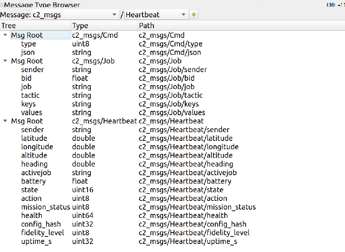
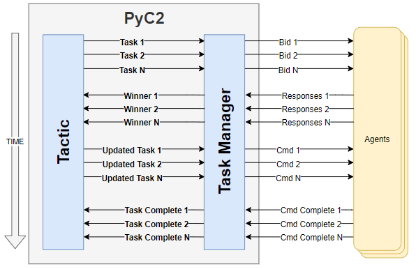
As mentioned in Section 4.2.1, ROS is utilized throughout RISE and is the common API interface. As with any ROS-based system, the interfaces between nodes are well defined by ROS messages, publishers, and subscribers. Agents in the swarm primarily interact through three ROS 2 messages which we define: the Heartbeat, Cmd, and Job messages. Figure 7 shows the contents of these three primary messages utilized by swarm agents and Swarm Engine. Individual agents of the swarm must populate the elements of the Heartbeat message and send that information repeatedly on the /a2c/heartbeat topic. As agents receive tasking or other factors occur, they must update the respective fields in the message. All Swarm Engine entities listen to that message topic to automatically discover swarm agents and add them to their agent table. Likewise, Swarm Engine instances will broadcast the same Heartbeat message information on a /heartbeat topic so that swarm agents are aware of all the Swarm Engine instances that are online and other Swarm Engine instances are also aware of each other.
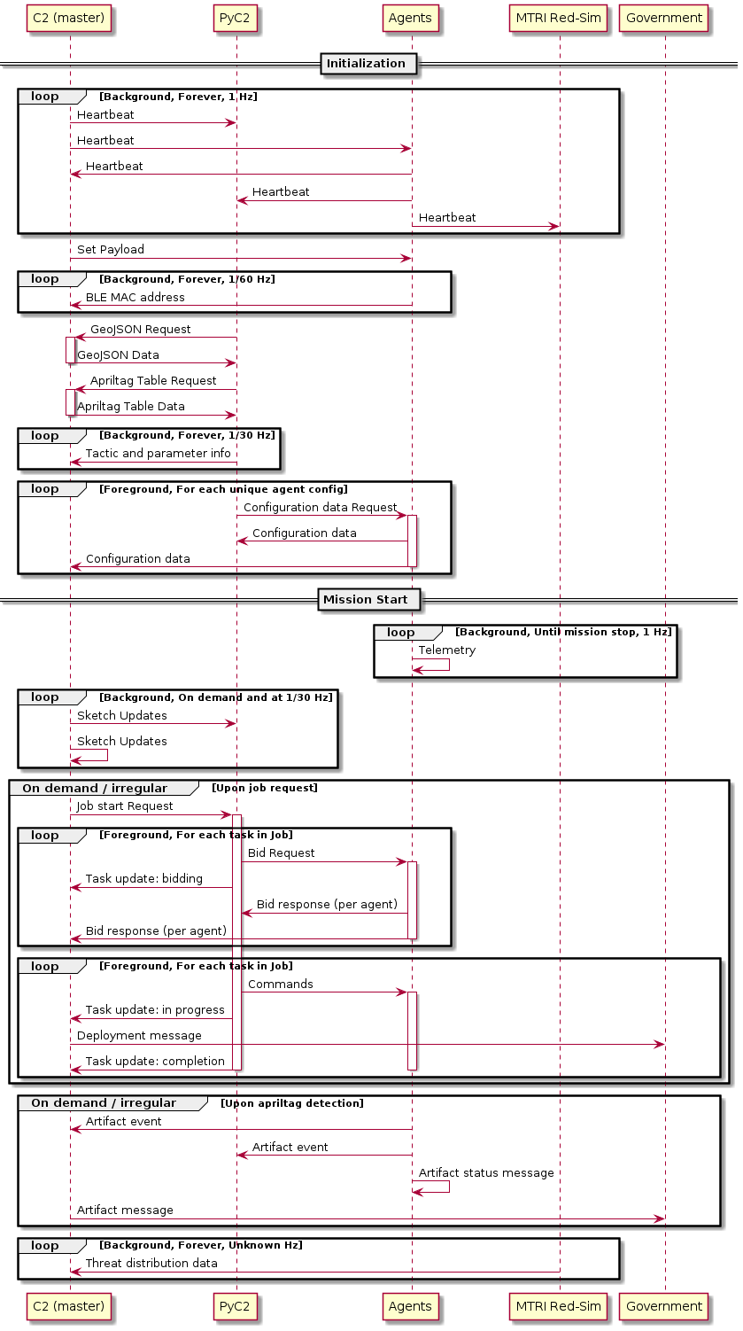
The Job and Cmd message are used as part of the bidding process that makes up the swarm task allocation. Figure 8 demonstrates how tasks are generated from tactic execution and are used to prompt swarm agents to bid via the Job message and bidding topics. After task evaluation has been completed based on bid responses, a command message is sent out to the swarm, instructing agents to complete the requested tactic. This interaction is facilitated by the Cmd message, with agents subscribing to the /command topic to determine if they have had a task assigned to them. If an agent has been tasked, logic flows into the agent primitive part of the architecture. Otherwise, agents continue to respond to task requests on the /bidding topic as additional tactics are executed over the course of the mission. A sequence diagram showing the swarm in operation is available in Figure 9.
4.4.1 Command API
Agent task assignment within RISE is handled via a centralized bidding system. While research on decentralized task allocation is quite common johnson2010improving and RISE has even been integrated with third parties that have implemented decentralized task allocation (see LABEL:sec:heron_integration), we found centralized tasking to be the ideal solution for RISE’s needs. First, centralized task allocation provides a much higher level of control of the swarm. It is abundantly clear when agents will take tasking and who the anticipated agents will be in a centralized system. Another primary reason for the centralized tasking is network load. With the numbers of agents in our use case, we need to limit network traffic wherever possible, and a centralized system allows for this.
The bidding system works through the use of the job and command messages described in Section 4.4. As a swarm operator provides tactic input, a series of tasks or ”jobs” are created within our system. These jobs are then sent out via the /bidding topic and agents respond with a heuristic-based bid. The agent heuristic looks at the job being requested, the location of the job relative to itself, battery life, vehicle health, and a few other factors, before it responds with a bid. PyC2 then evaluates all job responses received and eventually assigns tasking for all the jobs in a respective tactic. This final tasking is sent out via the /command topic and message. Figure 8 showcases the standard interaction over time for this overall process. Multiple tactics and jobs can be simultaneously bid out.
4.4.2 Intelligence API
All agents in the swarm are constantly searching for intel, regardless of the task they are performing. This intelligence is primarily gathered through the various platforms’ RGB cameras. While YOLO or some other variation of object detection has been utilized during RISE, intel in DARPA OFFSET field experiments was primarily represented by AprilTags 666https://github.com/AprilRobotics/AprilTag (See LABEL:sec:FX_scenario). Agents utilize an AprilTag detection algorithm to report to the swarm what they saw via a common detection message which contains information such as who saw the artifact, what does it represent in its current context, where was the artifact, and so forth. All agents and Swarm Engine instances listen for all reported detections from each other. As detections are reported, agents record the events in another subcomponent of Robot Core called the central data store. This information is stored and queried by certain primitives as any prior or dynamic intel is required for that primitive execution. Section 5.5.1 discuses how Swarm Engine visually represents reported intelligence from swarm agents.
5 RISE: User Interface
We built our C2 user interface to balance the needs of swarm commanders, operators, and health engineers. Swarm commanders are primarily concerned with situation awareness (SA), one aspect of which is “the perception of elements within a volume of time and space” endsley1995toward. Elements of interest include blue and red force positions, terrain layout, and mission plan data. Although operators must similarly maintain SA, they are also responsible for swarm command—the issuance of tactics that effectuate the commander’s plan. Given that robotic swarms interact with the environment, tactics are inherently grounded in a temporal and spatial context. The nature of SA and tactic invocation therefore implies that both the commander and operator primarily communicate with the swarm through the environment. On the other hand, swarm health engineers, as do researchers, practitioners, and developers, require access to detailed information that commanders and operators do not necessarily require. Agent task status, logs, component-level health information, and trajectory information are example data that engineers use to diagnosis issues occurring during a mission. Although, health engineers utilize SA and may aid swarm command, being able to quickly locate and interact with specific agents is critical to their success. Figure 10 illustrates how we balance these requirements.
The proposed cross-platform compatible interface was refined through an iterative design approach spanning four years. Our experiences participating in five large-scale field experiments across five Combined Arms Collective Training Facilities (CACTFs), along with periodic field integration testing and regular development, helped inform our design. As shown, the interface is divided into an interactive panel (left) and scene view (right). Given that the environment is our primary communication channel for SA and swarm command, we appropriate significant screen real estate to the scene view. Bandwidth is further maximized by abandoning traditional WIMP (windows, icons, menus, and pointers) design patterns. Instead, we implement a context-sensitive gesture-based user interface, whereby users interact with C2 via sketch commands. This decision also serves our desire for cross-platform capability, as we are able to preserve limited mobile device screen space. In the remainder of this section, we expand on these ideas and describe our interface in detail.
5.1 Cross Platform Compatibility
We designed a cross-platform compatible C2 by implementing techniques that utilize only 2D input, which we regard as the least common denominator among all input devices. Mouse, stylus, and touch input are inherently 2D. Three-dimensional controller and hand pose data can be made 2D via planar projections. For this reason, baseline C2 techniques learned on one system transfer to all supported systems. To date, we have ported our software to Windows, Linux, Android, HoloLens 2, and HTC Vive. It is important to note, however, that although we implement a common cross-platform interface, we are still able to exploit affordances offered by more capable systems. Additional information on alternative HMI interfaces supported by RISE can be found in Williamson2023.
5.2 Gesture Interface
Human motion that intentionally conveys information is a gesture. In the context of this work, gestures are motion patterns captured by an input device that map to software commands—when we recognize a known pattern, we invoke the associated function. To recognize input patterns, we employ Jackknife jackknife, a device-agnostic custom gesture recognizer.
Being device-agnostic means we are able to recognize mouse, touch, stylus, hand, and 3D controller gesture input, among other modalities using the same recognizer, which enables rapid integration of new input modalities. Being customizable means the recognizer learns from a small set of example input patterns. Jackknife specifically achieves high accuracy () with only one training sample loaded and improves with more training data777On 2D gestures specifically, Jackknife achieves 95% accuracy in a writer-independent recognition scenario with two templates loaded.. Since we only require minimal training data, users can customize the interface according to their preference, which has potential to increase learnability and memorability nacenta2013memorability. Further, because Jackknife uses a nearest neighbor pattern matching strategy, we can train the recognizer online in real time, enabling us to define new gesture classes on demand. When RISE implements a new feature, but the associated invocation gesture is unknown, our interface prompts the user for training data, after which the recognizer is retrained and the new feature is immediate accessible. This enables PyC2 to employ new tactic and sketch parameter types without direct C2 support.
All interface functions are accessed via gesture commands, including system commands to start and stop missions, agent commands to access logs and video feeds, and tactic and tactic parameters commands. Besides preserving screen space, an additional advantage in using gestures over WIMP design patterns is that C2 and PyC2 developers can add new functionality without having to reorganize menu hierarchies or toolbars, thereby accelerating development time. More importantly, however, gestures reduce mode switching and allow the user to interleave commands, potentially increasing command throughput.
To aid swarm operators learn the user interface, we developed an interactive training module that walks users through the basic agent, command and control, and navigation interactions. Separately, all available gesture commands can be found through an online help system shows the user how to draw each symbol and informs them on their usage.
5.3 Agent Interface
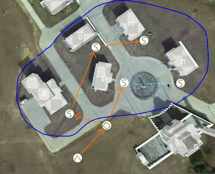
More so than commanders or operators, swarm health engineers are concerned with individual agents. We therefore provide access to essential agent interactions through the left panel shown (Figure 11). In this panel, we generate a list of all known agents—those for whom we have received one or more heartbeat messages. Each list entry communicates the agent’s name, payload, status, and tactic icon888Although agents execute primitives, we are able to trace its work back to the tactic that generated it.. The agent name’s color encodes its status, which may be idle (green), killed (orange), manually disabled (red), tasked (blue), or unknown (orange). This later state indicates that C2 has lost communication999Communication is lost when C2 has not received a heartbeat in seven seconds with the agent.
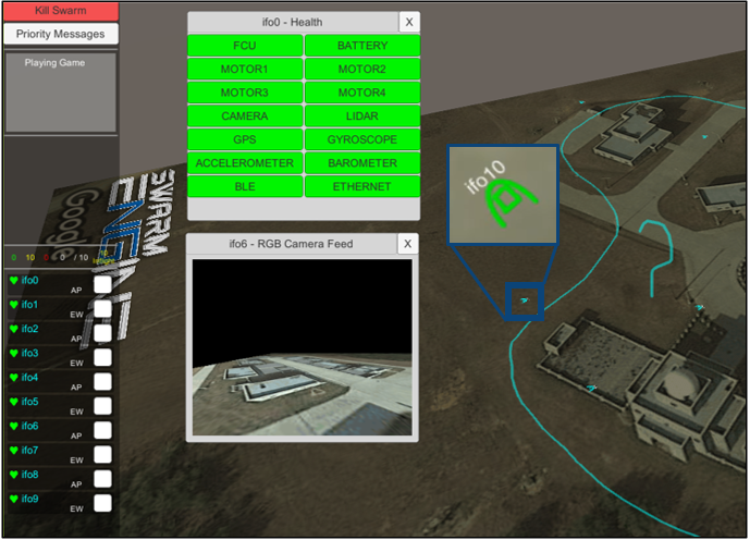
A user may access agent-specific data by gesturing on the agent’s button, where one’s initial contact point selects the agent. A right-swipe causes C2 to position the camera over the agent in the scene view. An h gesture opens the agent’s health information window wherein all relevant hardware components are listed with color coded status, those being nominal (green), missing (gray), intermediate (yellow), or critical (red). Color and depth camera streams from the agent can be viewed by h and ), respectively. Finally, L displays the agent’s logs. Although we are able to provide access to additional features, these were found to be most relevant for initial agent SA and diagnosis. A health swarm engineer will have access to additional information via SSH remote terminal access.
We present each agent as an icon within the scene view using a platform-specific symbol. Its color reflects the agent’s status using the same scheme described above. Within the agent icon, we render a tactic symbol that reflects ongoing or previously completed work in which the agent is or was engaged. In an early user interface iteration, we instead rendered agents as 3D models. However, other than being more aesthetically satisfying, they provided no clear advantage, which we opted for a less resource intensive variant.
5.4 Command and Control (C2)
The heart of swarm command in RISE comes down to specifying tactic commands, their inputs, and their execution order. These three elements are brought together through our sketch-based interface, as described next.
5.4.1 Tactic Invocation
To invoke a specific tactic, an operator must draw its associated gesture into the environment. When the gesture is recognized, C2 inserts an interactive tactic icon at the stroke’s centroid. The operator may then click on the tactic to open its associated popup window. This window comprises an input parameter list and two interaction buttons, one that immediately issues the tactic to PyC2 for further processing, and another that simply closes the window to enable mission planning. Table 1 shows five example tactics—their invocation gesture and required input parameters. The “Context” parameter specifies which sketch input parameter type a tactic will act upon.
The location of a tactic icon within the environment is relevant in that tactics optionally use position information to infer operator intention. To illustrate, our scan building tactic infers an operator wishes to scan that building which is closest to the icon. Tactics make similar inferences on sketch parameter input. Our overhead scan tactic, for example, operates on the closest explore area sketch (an input parameter type discussed below). For this reason, an operator may drag their tactic icons through the environment in order to precisely assign position.
Once invoked, tactic status is encoded into the icon’s color, being one of the following: pending (black), in progress (blue), failed (red), or successfully completed (green). We also add a tactic button to the left panel in order to provide a quick enumeration of ongoing work as well as provide access to additional developer and swarm heath engineer data. This includes access to children tactic and primitive data and agent waypoint lists when applicable. As the list grow long, it becomes difficult to correlate specific tactic buttons with ongoing field work. However, utilizing spatial memory, one may also return to the tactic icon within the scene view at any time in order to access the same information via a pop window. To cancel a tactic as well as its children tactics and primitives, one may simply scribble-erase the icon.
| Tactic Name | Gesture | Parameter | Type | Description |
| Examine Object | Context | POI | Use UAV to scan an object of interest. | |
| Radius | float | Radius of sphere around object. | ||
| Follow Route | Context | Path | Request an agent to traverse the nearest path. | |
| Altitude | float | Height in meters that UAV will assume. | ||
| Distance | float | Distance between points. Zero to force simplification. | ||
| Use Chaining | bool | Issue one point at a time, for testing only. | ||
| Hold Position | Context | Path | Move a set of agents to points along the perimeter and hold. | |
| Altitude | float | Height in meters that UAV will assume. | ||
| Duration | float | How long to hold. | ||
| Agent Count | int | Number of agents to place along perimeter. | ||
| Overhead Scan | Context | Explore | Fly UAVs over area to find artifacts. | |
| Altitude | float | Height in meters that UAV will assume. | ||
| Cell Size | float | Minimum linear distance between waypoints in meters. | ||
| Agent Count | int | Number of agents used to scan area. | ||
| Safe Land | Context | None | For a given air vehicle, find nearby safe location to land. |
5.4.2 Tactic Chaining
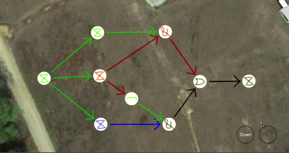
An operator rarely performs only a single tactic. Rather, he or she deploys multiple tactics in a specific order to advance particular mission objectives. The coordination of multiple tactics is therefore an important feature that we support via tactic chaining. As illustrated in Figure 12, an operator is able to link two tactic icons together via a sketch gesture. The combination of multiple links forms a directed acyclic graph. When an operator issues the root node tactic, C2 submits the entire graph structure to PyC2 for further processing. By default, children tactics execute only after their parent tactics successfully complete. In other words, parent node status propagates to children nodes, and if any parent tactic fails, the child tactic similarly fails. However, this propagation behavior can be modified via the use of logic gate tactic nodes.
| Gesture Legend | |||||||
|---|---|---|---|---|---|---|---|
| Conjunction | Create agents | Disjunction | Negation | ||||
| Overhead scan | Scan building | Timer | |||||
Logic gate tactic nodes are identical to standard tactics in implementation. One difference is that they override the default propagation behavior (see Section 6). PyC2 presently implements negation, conjunction, and disjunction. The negation gate inverts the status of its parent tactic, which can be useful for planning contingencies. Disjunction gates output a success response if any parent tactic is successful, whereas conjunction gates requires that all parent tactics are successful. Logic gate tactic nodes enable an operator to express sophisticated mission plans in sketch input form.
5.4.3 Tactic Parameters
Tactics require input data that specify their precise behavior on invocation, e.g., a persistent surveillance loitering altitude or safe building standoff distance. Most parameters are typically determined empirically or resolved through automation, though during development or in special cases, an operator may need to specify alternative values. For this reason, certain input data can be modified by an operator through the popup window interface. Data types we found to be suitable for the popup window include numeric, text, and boolean input. However, other data types are more easily described via sketch-based interactions. Throughout the course of the DARPA OFFSET program in which we developed and integrated numerous primitives and tactics, we encountered a consistent demand for only three sketch interaction types: selection groups, points, and polylines.
-
•
Selection Groups: It is sometimes necessary, especially for developers and swarm health engineers, to be able to select individual agents or a group of agents upon which subsequent commands are assigned. To support this operation, we implement a lasso selection technique, whereby the operator may draw a stroke around those objects he or she wishes to group. The operator may continuously lasso select objects until satisfied. Those objects within each new stroke are combined with previous groups using disjunctive union logic, thereby allowing deselection. Any tactic issued by the operator will then be restricted to just those agents in the final selection group. Should the specified tactic generate children tactics, those tactics too will adhere to the same restriction.
-
•
Points: Points are geospatial location markers that specify a certain position within the environment, e.g., points of interest, rendezvous points, and breach points. Points are mapped to gestures such that when drawn, the associated point appears at the gesture’s centroid within the scene view. The point can then be drag around to a precise location in three-dimensional space, though through customization, axes can be locked to reduce error. For instance, it is common practice to lock points to the ground plane.
-
•
Polylines: A polyline is a curve specified by an ordered sequence of geospatial locations that may be open, or closed to form a loop. Sketch strokes serve as the mechanism an operator uses to input polyline data, as strokes are a natural and fluid form of communication. One can therefore use polylines to specify trajectories including preferred routes and boundaries (no-go zones, explore areas, and deployment zones). An operator enters a gesture into the scene view to select a polyline type. The operator then inputs a stroke that defines the initial polyline, after which he or she can modify by sketching directly onto the polyline. The modification stroke acts as a magnetic tool that pulls the polyline in the direction of the cursor. When the polyline type is a closed loop, self loops and intersections are removed. Example routes and boundaries are shown in Figure 10.
To aid with perception and comprehension, tactic developers may customize point and polyline types with unique gesture invocation and rendering properties. See Section 6 for additional information.
5.5 Situation Awareness
C2 provides several tools to aid in the perception and comprehension of swarm intelligence. Swarm commanders can use this information to estimate future status and decide next steps.
![[Uncaptioned image]](/html/2304.07651/assets/images/ui/building_colors.png)
![[Uncaptioned image]](/html/2304.07651/assets/images/ui/threat_map.png)
![[Uncaptioned image]](/html/2304.07651/assets/images/ui/acoustic_map.png)
![[Uncaptioned image]](/html/2304.07651/assets/images/ui/coverage_1.png)
![[Uncaptioned image]](/html/2304.07651/assets/images/ui/coverage_2.png)
![[Uncaptioned image]](/html/2304.07651/assets/images/ui/coverage_3.png)
![[Uncaptioned image]](/html/2304.07651/assets/images/ui/joint_coverage.png)
5.5.1 Artifacts
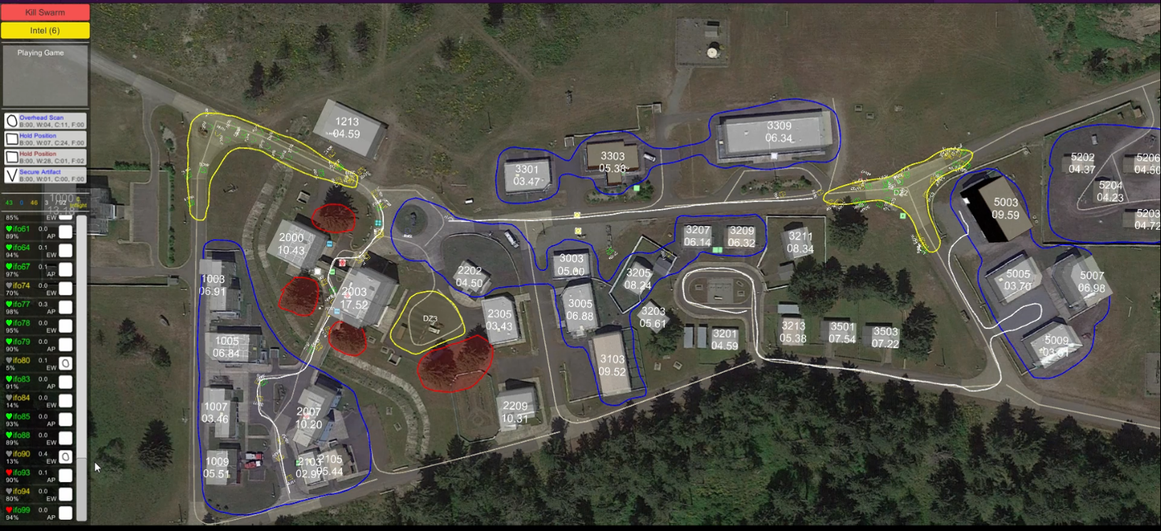
We define an artifact as an object of interest. C2 visualizes relevant artifacts detected by the swarm using military iconography as shown in Figure 13. We use standardized iconography to aid with comprehension because of their widespread use and ability to communicate essential information. Two DCRI levels self2005acquisition are supported, where C2 renders recognized artifacts using general class icons and identified artifacts using specific icons, e.g., person versus noncombat, medic, or hostile. To gather more information, an operator may view an agent’s video stream or command the swarm to surveil the artifact. We further render a red sphere around artifacts that pose a threat. Once neutralized, we remove the sphere.
5.5.2 Intelligence Information
As an alternative to the tactic and agent list view, a commander may opt to use our intelligence messages view. In this mode, swarm intelligence messages are listed in the left information panel. Unread messages are organized by priority level and require commander feedback to ensure they have been read. Messages referencing scene view data include hyperlinks that move the camera to the associated location. For example, “HVT reported in building 10” embeds a clickable link that moves the camera over the building.
5.5.3 Building Visualizations
C2 visualizes swarm intelligence gathered on building state information as shown in Figure 14. Specifically, we render a priori known building geometry in a checkerboard pattern. This indicates that the swarm expects to find a building, although its status is unconfirmed. Once the swarm verifies its state, we render the building solid. Additionally, buildings that house threats or intelligence are shaded with an oscillating red or blue tint, respectfully, and a quick glance of the scene view quickly reveals areas where additional attention may be required.
5.5.4 Grid Data Visualization
Swarms may track data that is well represented as a grid overlay. For this reason, we provide a mechanism by which swarm entities (any networked components including agents or third-party programs) may communicate custom grid data to C2. Figure 15 illustrates two examples born out of our collaborations with Michigan Tech Research Institute. The left grid visualization is a probability threat distribution where denser probabilities (brighter red) correlate with larger threats. Initially, initial uniform distribution evolves into a multimodal distribution as the swarm gathers intelligence and red forces are isolated. The right grid visualization illustrates an acoustic map. This is the area where deceptive firefight sounds would be heard if projected from under the operator’s cursor. One can see how grid data visualizations may be useful in several contexts; for example, instead of visualizing acoustic zone data, the swarm could report on network communication ranges, among other data.
5.5.5 Temporal Coverage
In order to visualize coverage over time, RISE C2 tracks agents as they move through the environment. Specifically, for each agent, across each frame, we cast rays from each camera into the virtual environment. The resulting collection of hit points yield a coverage estimate for the given frame. All hit points are then cached in a GPU-based voxel hash table representation of the environment that a custom temporal coverage shader uses to render the environment. Each entry stores a voxel ID and timestamp. When the said shader renders a fragment, it queries the hash table to determine when the voxel was last seen by an agent. As shown in Figure 16, if the associated voxel is absent from the hash table, we assume the voxel has never been observed, and so we render the fragment in a dark sepia tone. Otherwise, the fragment is colored based on a linear interpolation between full color to magenta, based on the time passed since the voxel was observed101010We fade to full magenta after twenty minutes..
This visualization has several practical applications. Practitioners, for example, can use temporal coverage data to quickly validate reconnaissance and persistent surveillance tactics work according to expectation. Swarm operators can maintain situation awareness to verify where within the mission area knowledge is absent or outdated. Figure 17 shows the temporal coverage visualization in use at the DARPA OFFSET sixth field experiment during a Northrop Grumman and BBN joint run scenario. The swarm commander was able to quickly measure progress against mission objectives and modify the mission plan accordingly to increase coverage.
5.6 Supported Environments
C2 supports three environment types of varying complexity. The simplest environment we support is an image based top-down map view that C2 loads from a public repository based on given GPS coordinates. This environment is useful for ad hoc testing that may occur during travel or when 3D models are unavailable. Second, C2 can load GeoJSON encoded data, which can be useful for randomized as well as custom scenario testing. However, when more complexity is required, developers can export custom Unity scenes that C2 can load. Finally, a number of custom scenes are also built into RISE, namely the Joint Base Lewis-McChord, Camp Shelby, and Fort Campbell CACTF sites.
6 Tactics Development Interface
PyC2 provides a straightforward interface for rapid tactic development. To implement a new tactic, one derives a new class from the PyC2 Tactic base class and specifies a tactic definition as shown in LABEL:listing:tactic_definition. All information required by C2 to invoke the tactic is included in this definition, including the command gesture, required input parameters, as well as human-readable descriptions of the tactic and its parameters. When PyC2 discovers a new C2 device via its heartbeat, we transmit all tactic definitions over the network. When C2 receives a new tactic definition, it will retrain the gesture recognizer (collecting new samples if required) so that an operator can immediately invoke the tactics. The associated tactic popup window (see Section 5.4.1) is automatically populated with numeric, boolean, and text parameter data entries. This design enables one to focus on core tactic logic without having to concern oneself with user interface integration, e.g., GUI layout design, arrangement, and embeddings within hierarchical menus.