GPSMirror: Expanding Accurate GPS Positioning to Shadowed and Indoor Regions with Backscatter
Abstract.
Despite the prevalence of GPS services, they still suffer from intermittent positioning with poor accuracy in partially shadowed regions like urban canyons, flyover shadows, and factories’ indoor areas. Existing wisdom relies on hardware modifications of GPS receivers or power-hungry infrastructures requiring continuous plug-in power supply which is hard to provide in outdoor regions and some factories. This paper fills the gap with GPSMirror, the first GPS-strengthening system that works for unmodified smartphones with the assistance of newly-designed GPS backscatter tags. The key enabling techniques in GPSMirror include: (i) a careful hardware design with microwatt-level power consumption that pushes the limit of backscatter sensitivity to re-radiate extremely weak GPS signals with enough coverage approaching the regulation limit; and (ii) a novel GPS positioning algorithm achieving meter-level accuracy in shadowed regions as well as expanding locatable regions under inadequate satellites where conventional algorithms fail. We build a prototype of the GPSMirror tags and conduct comprehensive experiments to evaluate them. Our results show that a GPSMirror tag can provide coverage up to 27.7 m. GPSMirror achieves median positioning accuracy of 3.7 m indoors and 4.6 m in urban canyon environments, respectively. ††footnotetext: ∗Corresponding author.
1. Introduction
Global Positioning System (GPS) has long been advocated as an indispensable infrastructure for many location-based services, including navigation for the automobile (Mezentsev et al., 2002; Liu et al., 2018), pedestrians (Mezentsev et al., 2005), ride-sharing (Chen and Tan, 2018), as well as asset tracking for smart factories (Ahmed et al., 2020). GPS receivers generally perform well in clear line-of-sight (LoS) regions with a sufficient number of visible GPS satellites. Such an assumption does not hold in those partially shadowed regions, e.g., urban canyons, flyover shadows, and factories’ indoor areas with iron sheds, where, unfortunately, navigation and tracking services are frequently needed. These services desire meter-level accuracy while positioning errors of conventional GPS in such shadowed regions often escalate to several hundred meters (Chen and Tan, 2018). The U.S. Department of Transportation reports that vehicles traveling through urban areas of New York City frequently fail to obtain reliable street-level accuracy for navigation with GPS (of Transportation, 2020). Google posits that positioning in these shadowed regions remains “the last great unsolved GPS problem” (van Diggelen, 2021).
Extensive research efforts have been devoted to tackling the challenging GPS problem. Infrastructure-based solutions, including GPS relays (ROGER, 2016; gemsnav, 2019a, b, 2016) and DGPS stations (Morgan-Owen and Johnston, 1995; geomax positioning, 2018) are available on the market. However, such solutions typically require infrastructure support, with the dense deployment of outdoor GPS stations and/or indoor anchors, which can be expensive and labor-intensive. In particular, each GPS relay and DGPS product (geomax positioning, 2018) requires its own continuous power source, making them challenging to deploy in existing urban canyons and flyover areas. Besides, laying power cables in a certain environment, such as gas factories and gas pipelines, is not allowed due to safety regulations (HSG47, 2000).
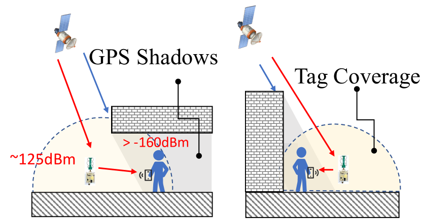
This paper demonstrates that it is possible to leverage passive, ultra-low-power backscatter tags to enable meter-level GPS positioning for unmodified mobile devices, e.g., smartphones, in shadowed regions. As plotted in Figure 1, these backscatter tags can be deployed on walls, windows and unenclosed parts of flyovers to improve the GPS performance in shadowed regions. Our line of attack starts from the rationale that we can induce multipaths in a deterministic manner using backscatter, which enriches the GPS propagation features that can be exploited in positioning algorithms. Building such a system needs to fulfill requirements along the following fronts:
(i) Sensitivity. GPS signals are extremely weak, i.e., below -125 dBm when reaching the Earth’s surface. The backscatter tags should have a high sensitivity to effectively capture and scatter such weak incidental signals.
(ii) Coverage. To ensure sufficient coverage, the backscatter tags need to provide sufficient gain as high as regulation permits. For example, the US regulation (Telecommunications and Administration, 2013) limits the coverage of a GPS repeater’s coverage within 30 m, while Europe (Telecommunications and Administration, 2010) limits a GPS repeater’s gain to 45 dB.
(iii) Performance and compatibility. The positioning algorithms must achieve comparable or higher accuracy compared to conventional GPS services, and should ideally require no hardware or firmware modification to existing GPS receivers (e.g., smartphones) to ensure wide acceptance.
Unfortunately, none of the existing systems meet the above requirements. On one hand, existing backscatter systems (Jang and Adib, 2019; Liu et al., 2013; Talla et al., 2017) are designed to reflect strong ambient signals, e.g., those from TV towers and WiFi access points. They cannot scatter the extremely weak GPS signals from outer space because their gain is not sufficient to overcome the fast attenuation of the weak GPS signals. While recent advances (Amato and Durgin, 2018; Varshney et al., 2019; Varshney and Corneo, 2020) use tunnel diodes to extend the coverage of backscatter communications, their sensitivity is still limited to around -90 dBm. On the other hand, existing GPS positioning algorithms (Nirjon et al., 2014; Liu et al., 2015) are no longer applicable in our scenarios since they do not consider the extra reflection paths created by backscatter tags.
the number of visible satellites.
We present GPSMirror, the first backscatter-based system that introduces the following innovative techniques to meet the aforementioned requirements. Inspired by recent innovations (Varshney and Corneo, 2020; Amato and Durgin, 2018), we employ tunnel diode as a core component to build up the RF front-end of our low-power backscatter tag to achieve amplification with -level power consumption. Previous designs create carrier wave (Varshney and Corneo, 2020) or modulate their bits on incident signals (Varshney et al., 2019) by employing a tunnel diode oscillator (TDO). However, our design target is completely different: we aim to carefully strengthen weak GPS signals according to regulations while preserving the original GPS waveforms with high fidelity to ensure correct decoding on smartphones. Instead, we propose a new design using the tunnel diode amplifier (TDA) (Munsterman, 1965), and achieve high precision on specific gain and bandwidth control using two resonance circuits (Varshney and Corneo, 2020). Additionally, to achieve the extreme sensitivity, GPSMirror hinges on a series of hardware innovations, including a circularized antenna design to capture a wide range of GPS signals while reflecting them to the shadowed regions, a coupling circuit with an open loop ring (OLR) to reduce the return loss caused by the solder of circuit component in the transmission line (TL), a noise suppression design to minimize SNR degradation caused by tunnel-diode based reflective amplifier.
We design a novel positioning algorithm that takes advantage of the tag-manipulated paths to (i) achieve positioning with comparable precision to LoS GPS areas, and (ii) dramatically improve positioning precision to meter level in cases where conventional algorithms are significantly compromised (tens to hundreds of meters precision) in NLoS conditions. GPSMirror only requires the assistance of a single tag and works on smartphones as a software update without any hardware/firmware modification.
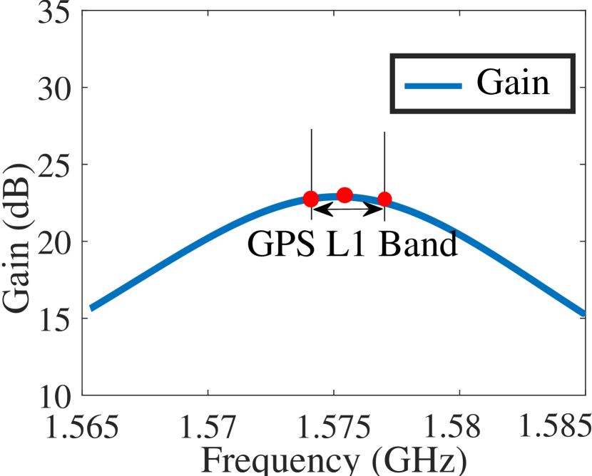
We prototype the GPSMirror tag with off-the-shelf components and benchmark its hardware performance through microscopic measurements. We further deploy GPSMirror tags in four real-world scenarios to verify their effectiveness. Experimental results show that a GPSMirror tag achieves a flat 22 dB gain in the L1 band and covers an area with a radius of about 27.7 m for smartphone reception in an urban canyon and 30 m in a corridor. The positioning algorithm achieves a median position error as low as 3.7 m in indoor scenarios and 4.6 m in an urban canyon. The main contributions are summarized as follows:
(i) GPSMirror is the first backscatter system that scatters signals from orbiting satellites. The hardware design pushes the limit of backscatter in that it can re-radiate weak GPS signals as low as -125 dBm with sufficient coverage.
(ii) We propose novel GPS positioning algorithms to extend GPS positioning services in shadowed or indoor regions where conventional GPS positioning fails or is severely undermined. It works seamlessly with off-the-shelf smartphones without any hardware or firmware modification.
(iii) We implement and evaluate the GPSMirror in real-world environments using off-the-shelf smartphones from different manufacturers. Our experiments verify the feasibility and compatibility of GPSMirror .
2. Overview
The GPSMirror system comprises the hardware design of backscatter tags and the positioning algorithms on smartphones to fully use the signals re-radiated by the tags.
(i) Hardware design. We employ two key innovations to build up the GPSMirror tags: a high-sensitive RF front-end and a tunnel diode-based reflection amplifier.
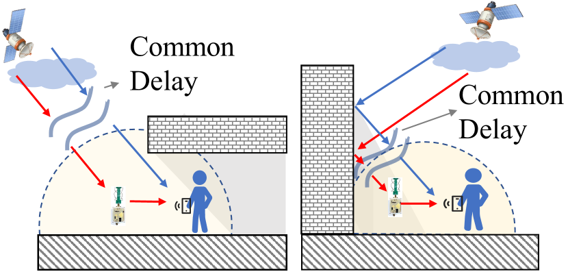
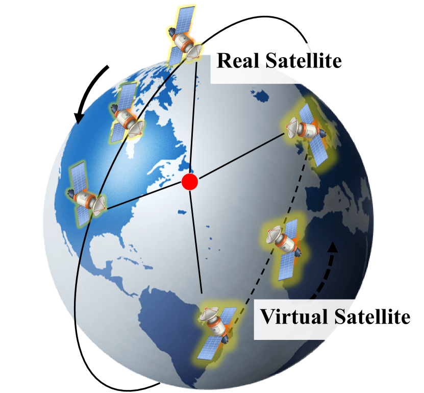
(ii) Positioning algorithm. We present an algorithm to subtly use GPSMirror tags to improve the GPS positioning performance in shadowed regions. When the number of visible satellites is inadequate for conventional GPS positioning (Figure 1 (a)), we construct virtual satellites with a single GPSMirror tag to guarantee coverage. When the number of visible satellites is adequate (Figure 1 (b)), we take advantage of the valid propagation path through GPSMirror tags to eliminate propagation errors of non-line-of-sight (NLoS) and improve accuracy.
3. Hardware Design
This section describes the hardware design of GPSMirror tags that can scatter weak GPS signals with sufficient coverage.
3.1. Pushing Scattering Coverage to the Limit
A fundamental challenge facing GPSMirror is the dramatic attenuation when backscatter tags re-radiate GPS signals, which severely limits the coverage of the GPSMirror tags. To maximize the coverage, the tags should be able to enhance the energy of the scattered GPS signals under the regulation permit (Telecommunications and Administration, 2013, 2010). Such a capability can be characterized by the standard backscatter reflection coefficient (Liu et al., 2014; Jang and Adib, 2019), i.e., the ratio of the amplitude of the reflected wave to the incident wave:
| (1) |
where and stand for the impedance of the internal circuit and the antenna, respectively. The gain of the backscatter tag is defined as (Munsterman, 1965). Obviously, when is negative, the gain is greater than 1, i.e., the signals are amplified after re-radiated by backscatter tags.
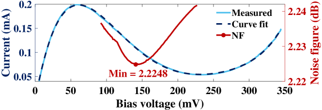
To achieve this, we adopt tunnel diodes as a core component, as they can realize negative resistance with -level power consumption. Plotted in Figure 2 is the IV-Curve of the diode, which holds a region of negative resistance (NR) due to the quantum tunneling effect (Varshney et al., 2019). The negative resistance () can be calculated from the slope of the IV-Curve. For MBD1057, which is used in GPSMirror, is about in our design with a bias voltage set around .
Classical tunnel diode was invented in the 1950s (Jonscher, 1961) and revived in recent backscatter systems (Amato and Durgin, 2018; Varshney and Corneo, 2020; Varshney et al., 2019) as a low-power amplifier. These systems aim to use a tunnel diode oscillator to re-modulate the incident signals, e.g., in the form of low-rate ASK or FSK, which can be decoded by a specialized demodulator. In other words, the backscatter tag’s modulation differs from the signal source. In contrast, GPSMirror needs to provide a high gain while preserving the incident signal’s waveform. Therefore, we employ the tunnel-diode-based reflection amplifier (TDA) (Farzami et al., 2017; Munsterman, 1965) to build GPSMirror instead.
Gain and bandwidth. The of the tunnel diode is about while standard antennas’ impedance is . To realize the amplification effect according to Equation 1, we need an impedance matching network to transform the impedance of the internal circuit’s to make it approach .
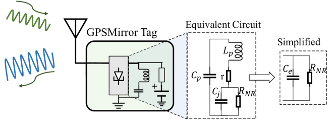
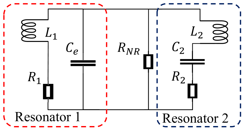
Yet, the tunnel diode cannot simply be regarded as a negative resistance alone. Instead, it is equivalent to a combination of multiple parasitic elements, including internal junction capacitance , packaging parasitic elements , and , whose typical values are , , and , respectively, according to the datasheet (Aeroflex, 2012). With the center frequency fixed in GPS L1 band, we simplify the tunnel diode circuit by series-parallel conversion step by step and then acquire an equivalent circuit as plotted in Figure 3, where the equivalent capacitor is about pF.
The conventional approach directly computes the overall impedance of the tunnel diode and builds a matching network. However, as the tunnel diode amplifier is susceptible to impedance changes, a straightforward search for values as in the conventional approach may introduce more parasitic parameters during manufacturing, resulting in unexpected performance.
To address this issue, GPSMirror achieves desired bandwidth and gain by using two resonance circuits instead, thereby making the circuit highly repeatable and easily debugged. The first resonant circuit aims to eliminate the effects of the parasitic elements inside the tunnel diode, while the second considers the impedance changes caused by the first resonant circuit and tunes the circuit to desired bandwidth and gain. In a typical series “LC” resonator circuit, the relationship of inductance , capacitance and frequency can be described as (Zhao et al., 2020):
| (2) |
Given the equivalent capacitance inside the tunnel diode, the only suitable inductance can be derived.
Then, the gain and bandwidth can be estimated through the quality factor , i.e., the ratio of resonant frequency to bandwidth, given by
| (3) |
where is the parasitic resistance inside the inductor and transmission lines. A smaller contributes to a higher , and thus we use low-loss microstrip lines to route the circuit.
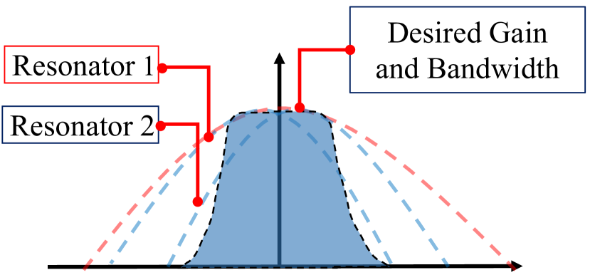
The second “RLC” circuit aims to achieve the desired gain and bandwidth. Given the needed bandwidth and impedance, we can determine a set of inductance and capacitance to achieve our goal according to the above equations. To ensure the gain’s flatness over the band, we slightly staggered the center frequency of the two resonant networks to ensure a consistent gain over the GPS band and sharp roll-off, which is the gain’s decreasing speed (Li et al., 2009), beyond the band, as plotted in Figure 4 (b).
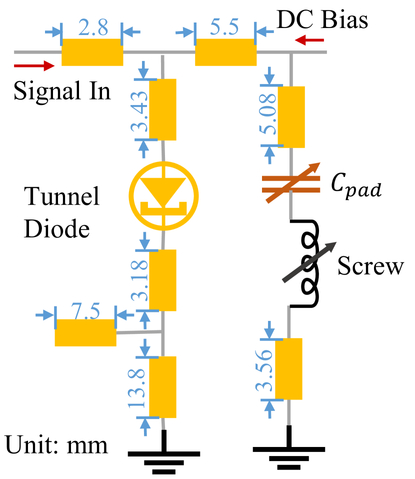

Unfortunately, integrated inductors and capacitors contain many parasitic elements along with soldering artifacts, making it difficult for circuit diagnosis. Thus, we transform the reflection amplifier circuit, as illustrated in Figure 4 (a), to practical microstrip lines on a PCB substrate to ensure the accuracy, as illustrated in Figure 5 (a). Furthermore, to deal with the PCB manufacturing imprecision that causes the resonant frequency to deviate from the design, we employ a tuning stub on board to adjust the center frequency of the first resonator and a tune pad with a tuning screw for the second one. Figure 5 (b) shows the stack-up of the GPSMirror reflection amplifier circuit. As the screw is closer to the tuning pad, the values of and increase and the resonant frequency of resonator 2 decreases, and vice versa.

3.2. High-Sensitivity RF Front-end for GPSMirror
Sensitivity (McCann, 2009) is a measure of the magnitude of input signal needed for the amplifier to produce full output. To scatter GPS signals with sufficient gain, GPSMirror must be sensitive enough to acquire the weak GPS signals in the first place.
This is different from traditional passive backscatter tags which do not need to detect and amplify the incident signals and hence do not need to optimize sensitivity. It also differs from traditional radio receivers which consider the modulation/encoding gain as part of the sensitivity. In effect, the sensitivity of GPSMirror is the detector sensitivity which describes how efficiently the radiation is converted into a usable signal. We design a highly sensitive RF front-end for GPSMirror via three steps, including an antenna design that maximizes the incident signals, a low loss coupling design that reduces the return loss when the signal is coupled into the internal circuit, and a low noise amplifier design that minimizes the current noise in the circuit.
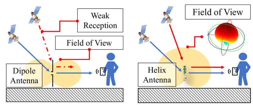
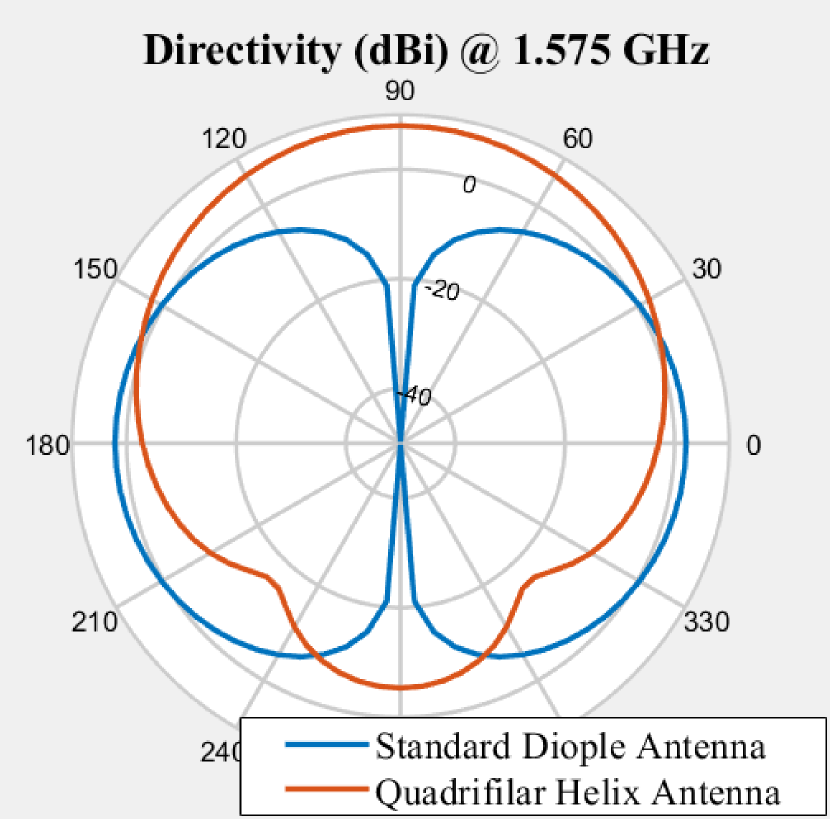
Capturing and radiating signals with a wide field-of-view (FoV). Traditional backscatters (Liu et al., 2013; Zhao et al., 2019; Varshney et al., 2019) employ dipole antennas to scatter signals within the azimuth plane. In contrast, GPSMirror reflects GPS signals over a wide 3D FoV by adapting the classical Quadrifilar Helix Antenna (QHA) structure (Son et al., 2008).
We build the antenna with a diameter of 3.8 cm, a comparable size to GPSMirror tags. The wavelength of the GPS signal in the L1 band is known and the remaining parameters of the antenna can be acquired from the helix antenna structure equation (Son et al., 2008). We also conduct simulations in ANSYS HFSS to verify the above design choices. As plotted in Figure 8 (b), QHA significantly outperforms the standard dipole antenna in the horizontal upward direction with an average of 7.3 dB gain in all upward directions.
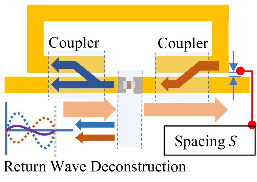
Reducing return loss in the transmission line. After the signals are captured by the antenna, they need to be passed to the RF front-end which may induce additional loss. A coupling circuit can be used to minimize such loss. Traditional backscatter tags use inductors and capacitors to build the matching network to couple the signals from the antennas to the internal circuit as shown in the Figure 8. However, these components need to be soldered on, which tends to damage the integrity of the transmission line (TL), resulting in the return loss, i.e., signal reflection and energy dissipation before coupling into the internal circuit.
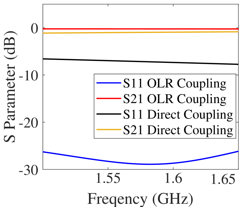
We design a new type of microstrip coupling circuit to minimize the loss of TL, as illustrated in Figure 7(b). We use a microstrip couple filter, which consists of two parallel TLs, to couple the returned signal to the open-loop-ring (OLR) circuit for additional transmission delays. Intuitively, when the signal coupled to the OLR circuit returns to the pad with the opposite phase, the return signal is canceled and loss minimized. The overall length of the loop determines the phase delay, an additional delay contributes to maximum signal deconstruction. We conduct an RF circuit simulation to verify our design. The simulation results in Figure 7 (c) show that our design significantly reduces the return loss. The S11 parameter, which is defined in Figure 7 (a), is considerably lower when compared to directly soldering a capacitor.
Operating with minimal noise. Before introducing the noise suppression design, we first describe the noise figure (NF) of the GPSMirror circuit. NF determines the degradation of SNR of the output signal compared to the incident signal, which should be minimized to maintain good signal quality. Specifically, the NF of a tunnel diode is given by (Munsterman, 1965; Yariv and Cook, 1961):
| (4) |
where is the resistance of the Ge board as plotted in Figure 3, the cutoff frequency, the operating frequency, the noise factor (Munsterman, 1965), and the negative resistance of the tunnel diode.
4. GPS-Compatible Positioning through Backscatter Signals
Conventional GPS algorithms on smartphones may perform poorly in the shadowed regions due to the following two reasons. First, inadequate visible satellites, which are caused by the obstruction of buildings, make the traditional algorithm unsolvable. Conventional GPS algorithms, however, require receiving signals from at least four visible satellites in order to estimate four unknown variables simultaneously (Google, 2016). Second, errors in distance measurements caused by NLoS propagation lead to inaccurate results.
Therefore, we develop a new algorithm that leverages the capabilities of GPSMirror tags to offer users the flexibility of prioritizing either extending locatable regions or improving accuracy. In this section, we first clarify the characteristics of scattered GPS signals and then proceed to describe the details of our positioning algorithm.
4.1. Features of Scattered GPS Signals
Different from traditional GPS relay systems that just amplify GPS signals to enhance the coverage, we modulate sequences on GPS signals with the “ON-OFF” switching on the GPSMirror tag. These sequences can help distinguish the scattered and non-scattered signals. Before elaborating on our algorithm design, we first introduce the accessible raw GPS measurements GPSMirror used (Google, 2016).
Signal strength measurements. Smartphones provide the carrier-to-noise-density ratio () as the signal strength measurements to indicate the strength of the received GPS signal. Since the GPSMirror tags can enhance the GPS signals, the scattered GPS signals have higher measurements than the non-scattered signals of the same satellites. Therefore, we can modulate significant features on to determine which piece of signals of which satellites have been scattered.
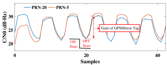
To discriminate the tag and extract the signal that is scattered by a GPSMirror tag, we configure the tag periodically switching between “ON” and “OFF” states to generate a certain pattern for discrimination. During the “ON” state, the DAC provides bias voltage to the tunnel diode amplifier and the GPSMirror tag starts to re-radiate GPS signals with gain; whereas the “OFF” state shuts down the bias voltage so the GPSMirror tag keeps silent. Such ON-OFF keying can significantly change the measured signal strength of GPS signals and thus changes the measurements on smartphones.
For a better understanding, we use a smartphone to record the samples with a GPSMirror tag deployed 1 m away. Plotted in Figure 9 is the measured from GPS satellite PRN-20 and PRN-5. The changes significantly with the GPSMirror tag switching from the “ON” state to the “OFF” state. We define the ratio of the between the “ON” state and “OFF” state is the gain of GPSMirror , and use this value to evaluate the coverage of GPSMirror tags in § 6.3.

Distance measurements. Smartphones provide two types of measurements related to the distance between the satellites and the smartphone: the Pseudorange and the Accumulated Delta Range measurements. The Pseudorange is a time-of-flight measurement calculated using the local clock of the smartphone, while the Accumulated Delta Range is a count of carrier cycles since the GPS sensor was started. Both measurements contain bias errors and cannot be directly used for positioning. Since we deploy GPSMirror to re-radiate GPS signals with “ON-OFF” scattering, the scattered GPS signals have additional delay which is not contained in conventional GPS algorithm (Humphreys et al., 2016).
Pseudorange of scattered GPS signals can be modeled as
| (5) |
where is the clock bias between a satellite and a receiver, which is the main bias error in GPS distance measurements and needs to be correctly estimated to extract accurate distance. is the distance between the smartphone and the GPS satellite without error, is the speed of light, and is the measurement error caused by other uncertain factors including ionospheric delay , tropospheric delay , etc. The scattered GPS signals have an additional delay while for the non-scattered signals. The distance measurements from accumulated carrier phase , denoted as , can typically be extracted from Accumulated Delta Range measurements. The relationship between and can be expressed by
| (6) |
where is the wavelength of the GPS signals, the phase offset relative to the initial reference phase value (commonly called ambiguity of whole cycles), and the measurement errors. Note that is fixed since the carrier phase is kept locked by the receiver and can be estimated using a double difference of pseudorange measurements between satellites. We can estimate by (Kayton, 2002).
4.2. Extending Locatable Regions under Inadequate Satellites
Under inadequate satellite conditions (4), the measurable propagation paths for localization are insufficient to estimate the position and clock bias. Hence, to turn these regions into locatable regions, we use GPSMirror tags to create additional measurable propagation paths through “ON-OFF” switching. To make the position estimation algorithm solvable, we then extract propagation delays through a GPSMirror tag and create “virtual satellites” that matched these measurable propagation paths. Finally, we estimate the position with combined measurements.
Estimating the position of virtual satellites. To correctly solve Equation (5), the virtual satellites must comply with the following rules. (i) A virtual satellite and the real satellite that emits the scattered GPS signals need to share the same pseudorange and Doppler shift to ensure the correctness of the solution. (ii) The orbit of a virtual satellite is still a true GPS orbit. (iii) A virtual satellite needs to be far away from the real satellite to ensure a small Dilution of precision (DOP) and make the positioning results robust to measurement uncertainty. To meet such requirements, we create virtual satellites by rotating the original satellites’ position vectors by 180∘ centered on the GPSMirror node, as shown in Figure 10. In particular, we create a virtual satellite with coordinates from a real satellite with coordinates according to the standard rotation equation (Altman, 1986).
Extracting the delay of scattered signals. The propagation delay, , through a GPSMirror tag in Equation (5) must be determined prior to positioning. Given that both scattered and non-scattered GPS signals are received by the same smartphone, the clock bias remains constant. Assuming we obtain nearby static samples of GPS signals and extract clock bias from non-scattered signals, we can assume the clock bias from scattered signals is equal to . By continuously comparing scattered and non-scattered GPS measurement pairs, we can estimate and update .
Positioning the receiver with a single GPSMirror tag. To estimate the receiver’s position, we use the weighted least squares (WLS) to combine the measured pseudorange directly from scattered and non-scattered GPS signals. The process of estimating the receiver’s position through WLS involves setting an initial position to activate the iterative algorithm. We then obtain the locations of the tracked satellites from the ephemeris, which provides GPS satellite’s orbital information forecasted by NASA.
Different from conventional algorithms, GPSMirror needs to calculate the distance from both the real and virtual satellites to the given initial position. Assuming satellite signals, including real and virtual satellites, are to be acquired. For the -th satellite (), using to represent its location and as the initial clock bias, then the true distance in the Equation (5) can be derived as , and the measured pseudorange follows
| (7) |
Next, we linearize the above equation. Assuming that the true position is , the difference between the target position (true position) and the initial position can be derived as
| (8) | ||||
which shows that and are linearly related. Therefore, both pseudorange measurements from real satellites and virtual satellites can be linearized using Equation (8).
Different from conventional GPS algorithms which simply apply the WLS solver with these measurements, the position estimation equations are reconstructed with the extracted delay of scattered signals. Specifically, suppose we obtain two consecutive pseudorange measurements, , from non-scattered GPS signals, and , from GPSMirror , which can be regarded as the signal from the virtual satellites. Let be the clock bias derived directly from the satellites and be the estimated clock bias, where is the true clock bias and is the propagation delay through the GPSMirror node. If we obtain measurements directly from the satellite and measurements from the GPSMirror node, We can organize the pseudorange of all measurements as
| (9) |
Then, we can estimate the through WLS:
| (10) |
where is the weight of each equation from the measurement uncertainties and denote the Jacobian matrix calculated using satellite positions. We can determine the true position as . As can be extracted by comparing scattered and non-scattered GPS signal pairs originating from the same satellites, a single GPSMirror tag may enable smartphone positioning with merely two visible satellites after obtaining . Additionally, accuracy can be improved with the following approaches if the number of visible satellites exceeds 2.
4.3. Differential Positioning for Accuracy Improvement
The other problem in shadowed regions is NLoS propagation. Intuitively, the lack of LoS causes rapid degradation in positioning accuracy. Since the LoS from the satellites to GPSMirror tags and LoS from the GPSMirror tags to smartphones are relatively easy to ensure, an important question is: can we convert the legacy positioning method that requires LoS from the receiver to satellites into a positioning method that requires LoS to a GPSMirror tag?
Our basic idea is to cast the GPSMirror tags as the reference stations, which create deterministic multipaths to improve positioning accuracy and mitigate the errors caused by random ambient reflections. Unlike conventional reference station-based systems (e.g., DGPS (Morgan-Owen and Johnston, 1995)) where the reference stations can process and compute the propagation delays correctly and deliver them to smartphones, the low-power GPSMirror tags with limited resources cannot process GPS signals or determine the propagation delays. Thus, GPSMirror needs to extract distance measurements and complete the computation using smartphones. Since the satellites are far from the ground (about 20000 km), scattered and non-scattered GPS signals from the same satellite in a short interval can be considered as arriving in parallel with the common propagation errors, which are mainly caused by NLOS in shadowed regions. We cast the GPSMirror tags as reference stations to reduce these errors.
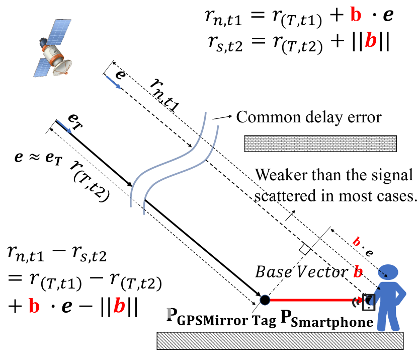
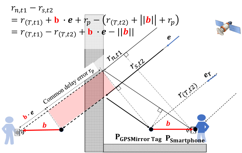
Distinct from DGPS stations, GPSMirror tags are incapable of directly processing GPS signals and extracting errors from the referenced propagation path. It is necessary to process signals from the referenced propagation path and eliminate propagation errors on smartphones. As depicted in Figure 11, a GPSMirror tag is employed to scatter GPS signals to a smartphone and differentiate the distance measurements of scattered and non-scattered GPS signals, thereby eliminating the common delay error. Pseudorange and phase measurements, both applicable for differential purposes, display comparable mathematical expressions. Owing to the superior resolution, phase measurements take precedence for positioning. But in some cases where phase data is unstable, pseudorange measurements can also be employed. The following delineates the detailed steps. Assuming two proximate samples of carrier phase measurements are obtained, from non-scattered GPS signal at and from scattered signals of the same satellite at . During this short interval, the angle of arrived GPS signal changes negligibly (Parkinson and Enge, 1996). Consequently, it can be assumed that proximate samples of scattered and non-scattered GPS signals share identical common errors, encompassing the delay induced by reflection and atmospheric delays and . Furthermore, differentiating measurements from scattered and non-scattered GPS signals aids in eliminating common errors that undermine positioning accuracy. Explicitly, can be acquired, where is the distance measurements from scattered GPS signals and from non-scattered GPS signals of the same satellites. According to (6), the equation can be expressed by
| (11) |
where is the difference of the phase offset and remains constant when the carrier phase is locked, both and are the distance between the same satellite to the smartphone at a different time. is the difference of clock bias between the 2 measurements. As the clocks of satellites are stable, mainly depends on the stability of the local clock of smartphones.
Different from conventional DGPS stations, GPSMirror cannot estimate the . Thus, we model an unknown vector b to stand for a position vector from the tag to the smartphone and estimate it on the smartphone. As shown in Figure 11, we use to denote the distance from the satellite to the GPSMirror tag from scattered GPS signals. Then we can presume based on the geometric relationship in Figure 11. Further, we can acquire , where is the unit directional vector from the satellite to the smartphone and can be expressed as
| (12) |
where is the change in distance from the satellites to the GPSMirror between and . We have established the relationship between the measurements and the base vector b and reorganized the equation by placing the known quantities on the left side.
| (13) | ||||
Given a for initialization, the Equation (13) can be linearized by
| (14) | ||||
with Newton’s iterative method. We use to represent the known quantities. Equation (14) can be rearranged to
| (15) |
Now according to Equation (15), the measured phase of GPS signals can be simply determined by the from the GPSMirror tag to the smartphone, which eliminates the requirement for LoS satellites. An intuitive explanation is that since the tag’s position is known and the position of satellites can also be calculated based on the orbit information, the propagation path between satellites and the GPSMirror tag is derived indirectly.
Then we start to solve the base vector with various formulas. We can obtain the base vector b by estimating the since they have a linear relationship. There are 4 variables in Equation (15), and . Thus, the system has sufficient equations to solve b. After we obtain equations, we have
| (16) |
Then, we can estimate the using a WLS estimation equation as
| (17) |
We then update and iterate until the is lower than a preset threshold. Then we can obtain the estimated base vector b. Further, since the location of GPSMirror tags and the floor plan is known after deployment, we filter out outlier b with impossible directions to further improve accuracy. Finally, we obtain the position of the smartphone with , demonstrated in Figure 11. Moreover, we can refine the direction and position of b based on the floor plan of the deployment site, thereby filtering out obvious incorrect directions to achieve higher accuracy.
5. System Implementation
In this section, we describe the implementation of GPSMirror, including fabrication of GPSMirror tags, and GPS data logger on receivers, i.e.,smartphones.
5.1. GPSMirror Tags
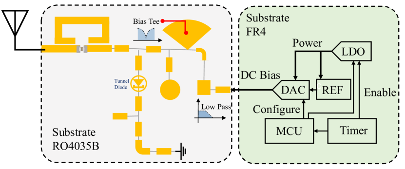
To provide accurate, stable and configurable bias voltage for the tunnel diode with off-the-shelf components, we prototype each GPSMirror tag with the following components: a tunnel diode to provide negative resistance for GPS signal amplification, a DAC to provide accurate bias voltage for the tunnel diode, a voltage reference chip that provides voltage reference against voltage-drift of the circuit, an MCU that configures and controls other components, a voltage buffer that holds the bias when other components are shut down to save energy and a low dropout regulator (LDO) that provides energy for the above components.
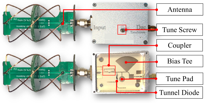
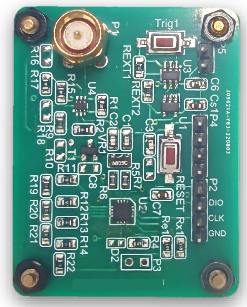
To facilitate manufacturing and commissioning, we split the above components into two circuits. One is the front-end circuit that handles the RF signals with a tunnel diode and micro-strip lines, the other is the baseband control circuit that configures the bias voltage for the tunnel diode. As shown in Figure 12 (a), we fabricate the front-end circuit on a low-loss Rogers 4350B substrate with an immersion gold craft to reduce the impact of surface roughness and oxidation on impedance. Each circuit is mounted in a customized metal cavity to avoid ambient electromagnetic noise. Shown in Figure 12 (b) is the baseband control circuit fabricated on FR4. In addition, we also build the customized antenna with a FR4 printed circuit board and copper wires.
| Components | Model | Price |
|---|---|---|
| Tunnel Diode | MBD1057 | $45.2 |
| MCU | KL03Z16 | $2.99 |
| Timer | TPL5111DDCR | $0.30 |
| Voltage Buffer | LTC2063SC6 | $1.38 |
| Voltage Reference | REF3012 | $0.45 |
| DAC | MAX5531 | $4.34 |
| LDO | TPS78218DDCT | $0.50 |
| Total | – | $55.16 |
Cost. Table 1 is the latest detailed breakdown of cost based on quotes for 1000 units, where the unit cost is around , but only if excluding the tunnel diode. Tunnel diodes contribute to 82% of the total cost owing to the lack of market demand. If GPSMirror were successfully promoted and widely deployed, mass production would further lower the unit price of tunnel diodes.
Power consumption. The tunnel diode consumes approximately 126 W according to Figure 3 and the off-the-shelf LDO consumes approximately 1.6 W. To reduce overall energy consumption, the MCU and DAC operate duty-cycled to provide precise voltage output and the voltage buffer helps to hold the bias voltage for the tunnel diodes when the MCU and DAC are shut-down. The scattering control and configuration of the DAC can be finished within 10 ms, thus the average power consumption of all these components is as low as 0.9 W. The voltage buffer consumes 6 W and the total power consumption is approximately 134.5 W. 134.5 W-power-consumption can enable the GPSMirror to continuously work for about 31 months with a coin-battery CR2477, which is also used in duty-cycled iBeacon (Beaconstac, [n. d.]) for a maximum of 24 months, while GPS relays/repeaters consume W-level power and require a plug-in supply. In addition, since distance measurements can be derived from any 1 ms-long GPS signal (Kayton, 2002), the tunnel diode can also operate in duty-cycled mode to amplify GPS signals. GPSMirror tags can achieve battery-free operation with RF or PV energy harvesters like other backscatter systems.
5.2. Receiver
We use various smartphones including Xiaomi 8, Huawei Mate20 Pro and Samsung Galaxy S20 Ultra with the GnssLogger 3.0 (Google, 2016) app installed for recording data. We process the recorded data and calculate the location offline.
6. Evaluation
In this section, we first evaluate the hardware performance of the GPSMirror tags with signal analyzers and smartphones. Then we conduct a series of experiments to test its coverage and localization performance under different conditions.
6.1. Experimental Setup
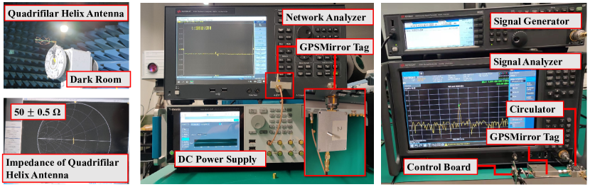
Hardware testbed. The hardware testbed is used to profile the GPSMirror tag, including the gains in the L1 band, the impedance of antennas, and the front-end circuit. As shown in Figure 13 (b), we use the network analyzer E5061B in an electromagnetic darkroom to measure the impedance and radiation pattern of the antenna and to tune the antenna to 50 ohms in the L1 band. The network analyzer N5225B is used to measure the reflection coefficient of the tag with a weak excitation power. The AWG 5000 arbitrary waveform generator provides accurate bias voltages to the GPSMirror tags. We use the Keysight MXG analog signal generator N5182B and the Keysight UXA signal analyzer N9020A to measure the gain of the GPSMirror tags. N5182B can generate RF signals as low as -140 dBm, and N9020A has a typical sensitivity of -150 dBm.
Ground truth. We use a Xiaomi LS-P laser range finder with a range error of 3 mm to obtain the ground truth for distance measurements. We use a Unistrong P40 board in real-time kinematic positioning (RTK) mode to obtain the ground truth for coordinates measurements. The position error of the Unistrong P40 in RTK mode is 8 mm when synchronized with differential stations. However, the Unistrong P40 board often fails to sync when it gets close to buildings or flyovers. We thus measure the coordinates of test points at least 30 meters away from buildings and derive all the required coordinates based on the distances measured by the laser range finder.
Deployment of GPSMirror tags. The GPSMirror tags can be deployed outside the building, in openings of a building or in unenclosed parts of flyovers to provide GPS service for pedestrians. The locations of the GPSMirror tags are registered in the map or floor plan and stored on smartphones.
6.2. GPS Signal Re-radiation
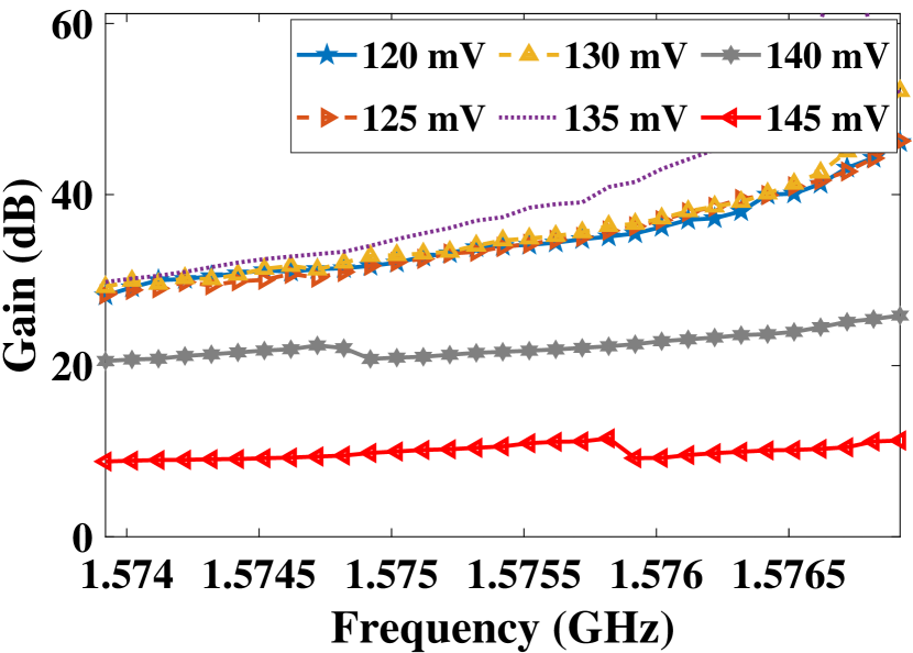
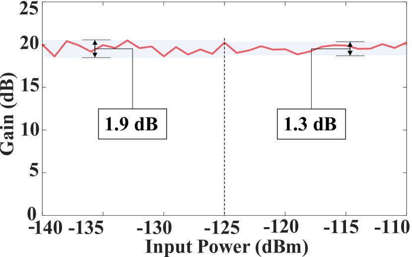
Performance profiling with a hardware testbed. To measure the gain of the GPSMirror tag, we use the signal generator to generate a -140 dBm RF signal that passes through the GPSMirror tag to the spectrum analyzer. The gain is obtained by comparing the signal strength of the signal generator’s output to the measured signal strength of the signal analyzer. The results are presented in Figure 14(a), where we can see the GPSMirror tag achieves about 22 dB gain with negligible distortion when the bias voltage is set at 140mV and higher gains are reachable when the bias voltage changes. We also evaluated the gain with different input signal power and the results are presented in Figure 14(b), where we can see the GPSMirror tag achieves flat gain with distortions less than 1.3 dB when the input power higher than -125 dBm and 1.9 dB when input power higher than -140 dBm. Thus, we can conservatively conclude that the GPSMirror tag has sufficient sensitivity ( -125 dBm) for scattering GPS signals.
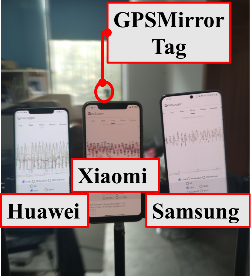
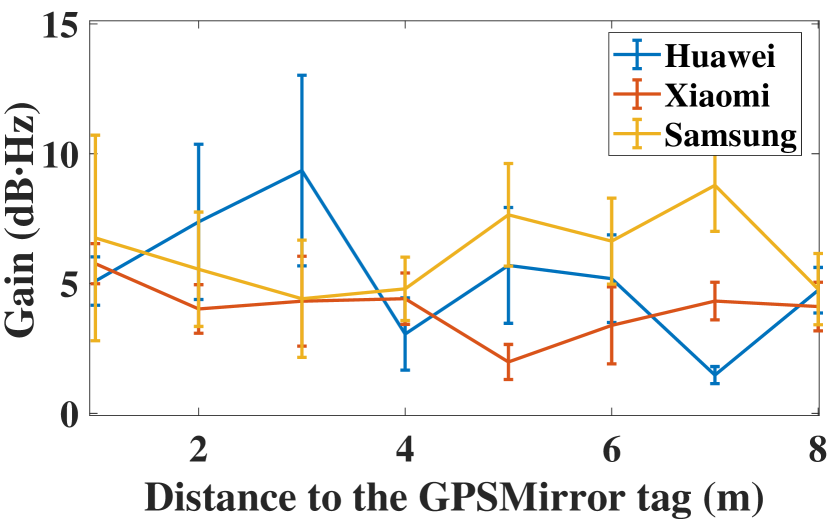
Received signal quality on smartphones. We test the signal quality on three different smartphones, including Samsung Galaxy S20, Huawei Mate20 Pro and Xiaomi 8, to verify the compatibility. As plotted in Figure 15, we deploy a GPSMirror tag in close to a window and simultaneously collect data using three smartphones. We compute the statistical average gain, along with a 95% confidence interval, for distances ranging from 1 m to 8 m away from the tag. Results demonstrate that smartphones from a variety of manufacturers are capable of effectively receiving GPS signals scattered by the tags.
6.3. Coverage of GPSMirror Tags


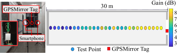
We define the coverage as the region where a GPSMirror tag’s “ON-OFF” switching can be detected and smartphones can position with the tag. GPSMirror enhances the GPS coverage in two main aspects. On the one hand, GPSMirror tags alter the propagation paths to increase the number of visible satellites. On the other hand, the GPS signals originally reachable to GPS receivers are strengthened by the GPSMirror tags. To evaluate the coverage performance from both aspects, we deploy GPSMirror tags in various scenarios including a 30m-long corridor, a sidewalk in an urban canyon, a classroom and a lecture hall. We set test points in each scenario and use smartphones to record raw measurements of both scattered and non-scattered GPS signals for 5 minutes at each test point. We use the of scattered GPS signals to minus that of non-scattered signals to present the enhanced performance. Then, we plot the mean value of 5 minutes in each test point as shown from Figure 16 to Figure 19.
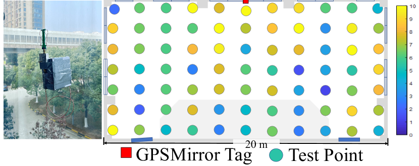
In all scenarios, GPSMirror tags strengthen the GPS signal by at least 3 dB including the farthest location. Specifically, at the farthest test point in Figure 18, which is 27.7 m away from the tag, there is ¿4 dB gain from the tag in both wall-mounted and tripod-mounted conditions. Since the nearest test point is about 2 m to the tag with gains of 9 dB, the drop-off of the gain is about 5 dB in this condition. Moreover, the farthest test point in Figure 19 is about 15.6 m to the tag with ¿3 dB in the three conditions. Therefore, we can conclude that the drop-off of gain is slow. Besides, Figure 16 shows that the GPSMirror tag can enable sufficient coverage within a radius of up to 30 m. Thus, the coverage of GPSMirror tags reaches the limit of the US regulation (Telecommunications and Administration, 2013), i.e., 30 m.
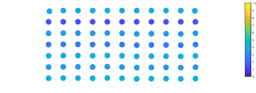
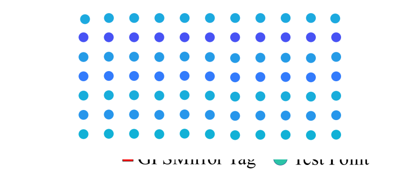
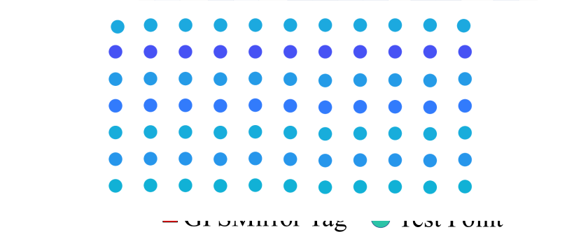
Impact of mounting methods. To evaluate the impact of different mounting methods, we conduct experiments to evaluate the performance of wall-mounted, window-mounted and tripod-mounted tags in both indoor and outdoor scenarios. Specifically, Figure 18 shows the coverage performance of a GPSMirror tag with different mounting methods in an urban canyon. We set 33 test points and each point is spaced 5 m apart. Figure 19 shows the coverage of GPSMirror tags in a lecture hall with different mounting methods. We set 77 test points and each one is spaced 2 m apart. Results show that different mounting methods have a negligible impact on the coverage.
Impact of deployment location. We notice that the deployment location of the GPSMirror tag influences the gain’s distribution in these test points. We compare Figure 19(a),19(b) and Figure 19(c) can draw a conclusion that it is better to deploy the GPSMirror tag close to the center of the open area for more uniform signal enhancement.
6.4. Positioning Accuracy
To fully exploit the performance of the positioning accuracy, we conduct the following experiment to evaluate the performance of both static and dynamic positioning. Further, we conduct a controlled experiment to explore the potential of using multiple GPSMirror tags for high positioning accuracy.
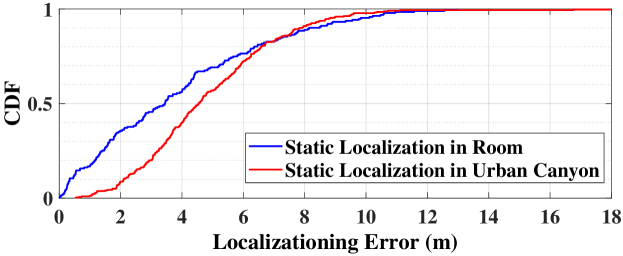
Static positioning. We evaluate the static positioning accuracy of the GPSMirror system in the following two scenarios: indoors, as shown in Figure 18 and 19, and in an urban canyon, as shown in Figure 18. To assess performance, we plot the cumulative distribution function (CDF) using the average position error of each point. The median positioning error is about 3.7 m in the indoor scenario and 4.6 m in the urban canyon as plotted in Figure 20. The localization accuracy in the indoor scenario is a little better than that in urban canyons. We speculate that this effect may be caused by the following reasons. The propagation path through a GPSMirror tag in an indoor scenario is more clear since windows are the only opening to the sky. On the contrary, GPS signals in an urban canyon are more complex since smartphones may receive more signals from propagation paths other than passing through the GPSMirror tags. Overall, the accuracy in both scenarios improves a lot with a GPSMirror tag eliminating the common delay errors.
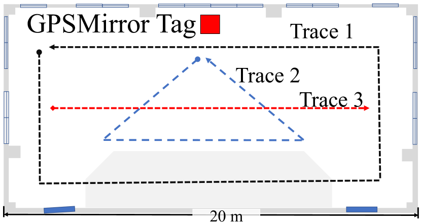
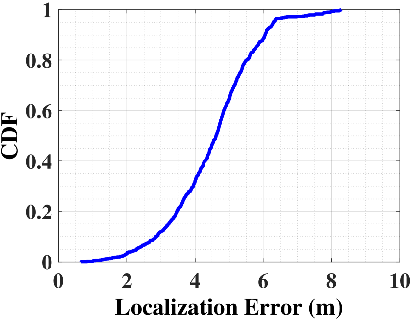

Dynamic positioning. To evaluate the performance of dynamic positioning, we perform a controlled experiment with a GPSMirror tag mounted on the window and set 3 types of trajectories for the receiver as shown in Figure 21. A volunteer walks along the trajectories with an average speed of about 25 cm/s per second and holds a smartphone recording GPS measurements. We compute the location based on every four samples and compare it with the ground truth, which is distributed every 1 m on the trajectories. The results show that we can achieve a median localization error of about 4.5 m with GPS signals only, which is sufficient in urban canyons and some indoor regions. However, the accuracy gets a little worse than in static positioning conditions. We speculate this may be primarily limited by the low sampling rate of the smartphone, which is defaulted to 1 Hz for energy saving. To eliminate the common error correctly, multiple samples are needed, but the correlation between these samples is reduced more in dynamic localization conditions, resulting in slightly worse accuracy. Increasing the sampling rate can mitigate this limitation. Some GNSS sensors for smartphones support higher sampling rates, e.g., 40Hz (U-Blox, 2021). It is possible to achieve this rate through firmware modifications (Shade and Madhani, 2018).
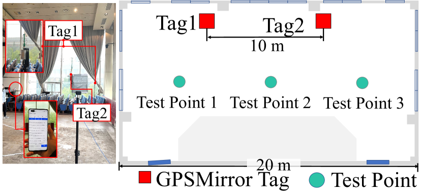
Positioning with multiple tags. To investigate the potential for enhancing localization accuracy using multiple GPSMirror tags, we conduct a controlled experiment with two tripod-mounted tags offering GPS-enhancing services simultaneously. These tags are synchronized via cable and operated on a time-division schedule. We established three test points and collected 180 samples at each using a handheld smartphone. The smartphone’s position was estimated with Tag1 and Tag2, and both base vectors from the tags were used for estimation. As illustrated in Figure 23, the average positioning accuracy of two tags at the three test points was approximately 2.6 m, 2.4 m, and 3.6 m, with 95 confidence interval error bars. Localization results using two tags are significantly better than those using a single tag.
6.5. Case Studies
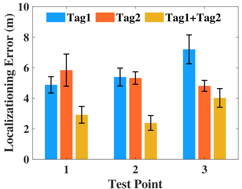
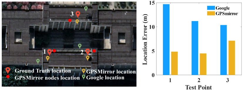
We deploy the GPSMirror tags and evaluate the positioning accuracy of our system in four real-world scenarios, i.e., large flat room (Factory, Figure 23), flyover (Figure 26), exterior of tall buildings (Urban canyon, Figure 26)), and center patio (Urban canyon, Figure 26). We use an open-source GPS position estimation project provided by Google as baseline (Google, 2016).
Figure 23 shows the results in a large flat room on the ground, a common architectural structure as in many factories. We deploy a single GPSMirror tag in the room and evaluate the localization performance in three positions. Google’s baseline algorithm fails to position in test point 2 and 3 due to insufficient visible satellites. In contrast, GPSMirror achieves the positioning accuracy of under 10 m for all test points.
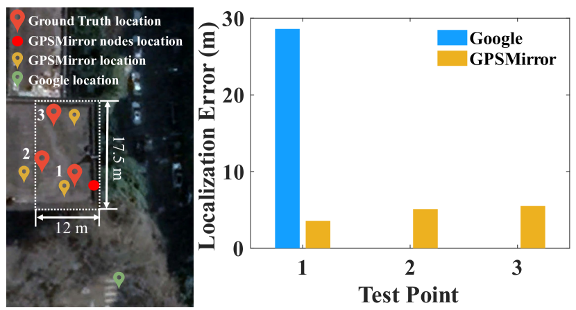
Figure 26 shows the results under a flyover, which is challenging for a single GPSMirror tag to provide GPS service. Because the middle is the vehicle way, the GPSMirror tag can only be deployed at one side, which is not the area that provides the best coverage. We evaluate the positioning performance in two test points. As expected, the positioning accuracy decreases on the opposite side of the road.
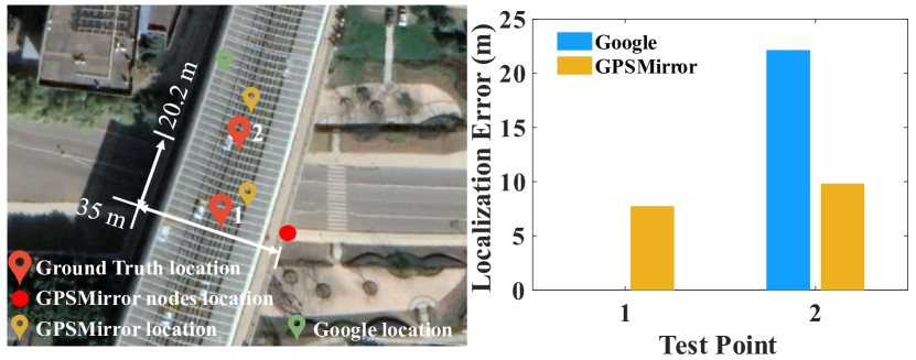
The exterior of tall buildings is a common view in urban areas. We deploy a single GPSMirror tag 12 m away from the building and try to provide high-accuracy GPS service near the building. In position 1 and position 3, GPSMirror achieves average performance while Google’s baseline algorithm degrades rapidly. However, the positioning accuracy of Google’s baseline in position 2 (LoS region) achieves better performance. This is as expected because the position is far from the GPSMirror tag while conventional GPS positioning algorithms can achieve good performance in LoS regions, which are not our target cases.
The center patio is a common architectural structure in an urban area, which is surrounded by tall buildings with only the middle part having a view of the sky. We deploy GPSMirror tags here to further evaluate the generalizability of our tags in downtown mega-cities. As shown in Figure 26, GPSMirror significantly improved the position accuracy for all test points.
7. Related Work
GPS relays. The commonly used GPS relays (gemsnav, 2019a, b, 2016) mainly consist of two parts. The first part includes an antenna and an LNA deployed outdoors, to receive the signals from GPS satellites. The second part is deployed inside the building and consists of a GPS transmit antenna and a power amplifier. These two parts are connected by an RF cable and powered by a plug-in source. Such GPS relays are power hungry, typically consuming -level power for coverage of less than 30 m (Telecommunications and Administration, 2013). They are not easy to deploy due to the need for a stable power supply and the complexity of routing RF cables. In contrast, GPSMirror re-radiates GPS signals by integrating an antenna and a reflection amplifier into a single module. It only consumes -level power and can be easily powered by a coin battery or an energy harvesting module.
GPS and wireless positioning. Recent efforts (Nirjon et al., 2014; Liu et al., 2015, 2018) have attempted to improve the performance of GPS positioning. CO-GPS (Liu et al., 2015) designs a cloud-offloaded GPS solution to save energy for portable sensing devices. GNOME (Liu et al., 2018) leverages Google Street View for accurate GPS positioning in urban canyons. COIN-GPS (Nirjon et al., 2014) develops a robust GPS receiver with a purpose-built directional antenna for indoor GPS positioning. GPSMirror is inspired by this literature while aiming to provide practical indoor GPS positioning services for off-the-shelf smartphones. DGPS (Weng et al., 2020; Morgan-Owen and Johnston, 1995) uses one or more reference stations to eliminate the propagation errors for accurate positioning. GPSMirror shares similar principles to reduce positioning errors, but differs from DGPS in that the positioning algorithm runs entirely on unmodified smartphones, merely using the GPS application programming interfaces (APIs).
Wireless indoor positioning systems, such as Bluetooth low energy (BLE) (Ayyalasomayajula et al., 2018; Instrument, 2016; BeaconTrax, 2022), ultra-wide-band (UWB) (Dhekne et al., 2019; Zhao et al., 2021; Qorvo, 2017; EHIGH, 2016), and WiFi (Ibrahim et al., 2018; Instrument, 2020), have demonstrated high precision for indoor localization. However, such specialized infrastructures entail laborious mapping and calibration at the deployment phase and also require a power supply for continuous positioning. They are not compatible with the GPS service on smartphones and have not seen wide deployment.
Tunnel diode-based backscatter. Recent research demonstrated that tunnel diodes enable orders of magnitude improvement in backscatter communication range with -level power consumption (Amato and Durgin, 2018; Gumber et al., 2020; Varshney et al., 2019; Amato and Hemour, 2019; Varshney and Corneo, 2020; Varshney et al., 2022). GPSMirror also uses a tunnel diode to amplify incident signals, but differs from the prior work through new noise suppression and precision impedance control mechanisms. Specifically, GPSMirror needs to be highly sensitive in acquiring weak GPS signals and to ensure that the scattered signals still preserve the modulated waveforms of incident signals. The backscatter design in GPSMirror is the first to meet these requirements. Moreover, GPSMirror strictly works as a reflective amplifier rather than a tunnel diode oscillator (Amato and Durgin, 2018; Gumber et al., 2020; Varshney et al., 2019; Amato and Hemour, 2019; Varshney and Corneo, 2020). GPSMirror does not need to generate a carrier by itself because it only captures and amplifies the GPS signals. Jodu (Varshney et al., 2022) also employs a tunnel diode to achieve a reflective amplifier for communication. However, it cannot be applied to GPSMirror because it suppresses the harmonics of carriers to reduce interference. The harmonics suppression would lead to distortion of GPS signals since GPS signals are spectrum-spread.
8. Discussion
Positioning error. GPSMirror demonstrates significant improvement in localization accuracy compared to other GPS solutions, however, there is still room for further improvement to reduce positioning errors. The source of the positioning error of GPSMirror may include (i) the average user range error (URE) set by government limitations, which is approximately 0.6m (government information about the GPS and related topics, 2020), (ii) wrong measurements due to low SNR, (iii) insufficient spatial diversity with the use of a single tag. The limitations (i) and (ii) are fundamental to GPS signals, while (iii) can be addressed through the deployment of multiple tags. In addition, the accuracy can be further improved by applying continuous-time Kalman filters and sensor-fusion techniques.
Deployment cost. The GPSMirror has several advantages over traditional GPS relays/repeaters in terms of cost efficiency for deployment. First, GPSMirror does not need a plug-in power supply, which can significantly reduce system deployment and maintenance costs. Second, GPSMirror costs 55.16 and 82 of the tag’s cost comes from tunnel diodes, which will further “reduce cost if developed at scale” (Varshney and Corneo, 2020), while a commercial GPS relay/repeater system with similar coverage under regulations will cost more (gemsnav, 2019a, 2016). Besides, GPSMirror also has a lower deployment cost than BLE beacons in GPS-shadowed regions. Typically, only one GPSMirror tag is needed to provide positioning services for smartphones, whereas at least three BLE beacons are required for the same purpose. The cost of a GPSMirror tag is cheaper than BLE beacons (such as an iBeacon, which costs 69 (Beaconstac, [n. d.]) for a set of 3). Therefore, GPSMirror is more cost-efficient for deployment.
9. Conclusion
We designed and validated GPSMirror , an ultra-low power system to expand accurate GPS positioning to shadowed and indoor regions for smartphones. The key enabling hardware in GPSMirror is the first high-sensitive backscatter that can re-radiate extremely weak GPS signals and provide enough coverage that approaches the regulation limit. Beyond GPS positioning, we also envision the GPSMirror design can be adapted to accommodate a wider range of use cases, such as satellite communications through backscatter.
Acknowledgments
We thank our shepherd and reviewers for their helpful feedback, which greatly improved the quality of the paper. This work was supported in part by the National Key RD Program of China under Grant 2020YFB1806600, the National Science Foundation of China with Grant 62071194, the Key RD Program of Hubei Province of China under Grant No. 2021EHB002, the Knowledge Innovation Program of Wuhan-Shuguang, the European Union’s Horizon 2020 research and innovation programme under the Marie Skłodowska-Curie grant agreement No 101022280 and No 824019.
References
- (1)
- Aeroflex (2012) Aeroflex. 2012. MBD1057 Datasheet. http://pdf.datasheet.live/datasheets-1/aeroflex_[metelics]/MBD1057-C18.pdf.
- Ahmed et al. (2020) Fahim Ahmed, Mark Phillips, Stephen Phillips, and Kyoung-Yun Kim. 2020. Comparative study of seamless asset location and tracking technologies. Procedia Manufacturing 51 (2020), 1138–1145.
- Altman (1986) SL Altman. 1986. Rotations, quaternions, and double groups. Clarendon.
- Amato and Durgin (2018) Francesco Amato and Gregory D Durgin. 2018. Tunnel diodes for backscattering communications. In 2018 2nd URSI Atlantic Radio Science Meeting (AT-RASC). IEEE, 1–3.
- Amato and Hemour (2019) Francesco Amato and Simon Hemour. 2019. The harmonic tunneling tag: A dual-band approach to backscattering communications. In 2019 IEEE International Conference on RFID Technology and Applications (RFID-TA). IEEE, 244–247.
- Ayyalasomayajula et al. (2018) Roshan Ayyalasomayajula, Deepak Vasisht, and Dinesh Bharadia. 2018. BLoc: CSI-Based Accurate Localization for BLE Tags. In Proceedings of the 14th International Conference on Emerging Networking Experiments and Technologies (Heraklion, Greece) (CoNEXT ’18). Association for Computing Machinery, New York, NY, USA, 126–138. https://doi.org/10.1145/3281411.3281428
- Beaconstac ([n. d.]) Beaconstac. [n. d.]. iBeacon Technology. [EB/OL]. https://www.beaconstac.com/apple-ibeacon-technology Accessed Jan, 2023.
- BeaconTrax (2022) BeaconTrax. 2022. Trax20220. https://www.beacontrax.com/product/trax20220-bluetooth-lte-m-ble-gateway/.
- Chen and Tan (2018) Kongyang Chen and Guang Tan. 2018. BikeGPS: Accurate Localization of Shared Bikes in Street Canyons via Low-Level GPS Cooperation. In Proceedings of the 16th Annual International Conference on Mobile Systems, Applications, and Services (MobiSys ’18). Association for Computing Machinery, New York, NY, USA, 150–162. https://doi.org/10.1145/3210240.3210316
- Dhekne et al. (2019) Ashutosh Dhekne, Ayon Chakraborty, Karthikeyan Sundaresan, and Sampath Rangarajan. 2019. TrackIO: Tracking First Responders Inside-Out. In 16th USENIX Symposium on Networked Systems Design and Implementation. USENIX Association, Boston, MA, 751–764. https://www.usenix.org/conference/nsdi19/presentation/dhekne
- EHIGH (2016) EHIGH. 2016. EHIGH EH100602D04 Datasheet. https://www.ehighuwb.com/product-item-11.html.
- Farzami et al. (2017) Farhad Farzami, Seiran Khaledian, Besma Smida, and Danilo Erricolo. 2017. Ultra-low power reflection amplifier using tunnel diode for RFID applications. In 2017 IEEE International Symposium on Antennas and Propagation & USNC/URSI National Radio Science Meeting. IEEE, 2511–2512.
- gemsnav (2016) gemsnav. 2016. RGA30-DV GPS relay. http://en.gemsnav.com/product_detail_10.html.
- gemsnav (2019a) gemsnav. 2019a. GRK-1 GPS relay. http://www.gemsnav.com/product_detail_60.html.
- gemsnav (2019b) gemsnav. 2019b. Q-GL1 GPS relay. http://www.gemsnav.com/product_detail_16.html.
- geomax positioning (2018) geomax positioning. 2018. GNSS Receiver Zenith35 Pro Series. https://geooprema.com/products/survey-equipment/survey-gps-gnss/geomax-zenith-35-pro-gps-gnss/.
- Google (2016) Google. 2016. GPS Measurement Tools. https://github.com/google/gps-measurement-tools.
- government information about the GPS and related topics (2020) Official U.S. government information about the GPS and related topics. 2020. GPS Accuracy. https://www.gps.gov/systems/gps/performance/accuracy/.
- Gumber et al. (2020) Karan Gumber, Francesco Amato, Corinne Dejous, and Simon Hemour. 2020. Nonlinear negative resistance-based harmonic backscatter. In 2020 IEEE/MTT-S International Microwave Symposium (IMS). IEEE, 603–606.
- HSG47 (2000) HSE Booklet HSG47. 2000. Avoiding Danger from Underground Services. https://www.spenergynetworks.co.uk/userfiles/file/hsg47.pdf.
- Humphreys et al. (2016) Todd E Humphreys, Matthew Murrian, Frank Van Diggelen, Sergei Podshivalov, and Kenneth M Pesyna. 2016. On the feasibility of cm-accurate positioning via a smartphone’s antenna and GNSS chip. In 2016 IEEE/ION position, location and navigation symposium (PLANS). IEEE, 232–242.
- Ibrahim et al. (2018) Mohamed Ibrahim, Hansi Liu, Minitha Jawahar, Viet Nguyen, Marco Gruteser, Richard Howard, Bo Yu, and Fan Bai. 2018. Verification: Accuracy evaluation of WiFi fine time measurements on an open platform. In Proceedings of the 24th Annual International Conference on Mobile Computing and Networking (MobiCom’18). 417–427.
- Instrument (2016) Texas Instrument. 2016. CC2640R2F Datasheet. https://www.ti.com/product/CC2640R2F.
- Instrument (2020) Texas Instrument. 2020. CC3230S Datasheet. https://www.ti.com/product/CC3230S.
- Jang and Adib (2019) Junsu Jang and Fadel Adib. 2019. Underwater backscatter networking. In Proceedings of the ACM Special Interest Group on Data Communication. 187–199.
- Jonscher (1961) AK Jonscher. 1961. The physics of the tunnel diode. British Journal of Applied Physics 12, 12 (1961), 654.
- Kayton (2002) M Kayton. 2002. Global positioning system: signals, measurements, and performance [Book Review]. IEEE Aerospace and Electronic Systems Magazine 17, 10 (2002), 36–37.
- Li et al. (2009) J-L Li, S-W Qu, and Quan Xue. 2009. Compact microstrip lowpass filter with sharp roll-off and wide stop-band. Electronics Letters 45, 2 (2009), 110–111.
- Liu et al. (2015) Jie Liu, Bodhi Priyantha, Ted Hart, Yuzhe Jin, Woosuk Lee, Vijay Raghunathan, Heitor S Ramos, and Qiang Wang. 2015. CO-GPS: Energy efficient GPS sensing with cloud offloading. IEEE Transactions on Mobile Computing 15, 6 (2015), 1348–1361.
- Liu et al. (2013) Vincent Liu, Aaron Parks, Vamsi Talla, Shyamnath Gollakota, David Wetherall, and Joshua R Smith. 2013. Ambient backscatter: Wireless communication out of thin air. ACM SIGCOMM Computer Communication Review 43, 4 (2013), 39–50.
- Liu et al. (2014) Vincent Liu, Vamsi Talla, and Shyamnath Gollakota. 2014. Enabling instantaneous feedback with full-duplex backscatter. In Proceedings of the 20th annual international conference on Mobile computing and networking (MobiCom’14). 67–78.
- Liu et al. (2018) Xiaochen Liu, Suman Nath, and Ramesh Govindan. 2018. Gnome: A practical approach to nlos mitigation for gps positioning in smartphones. In Proceedings of the 16th Annual International Conference on Mobile Systems, Applications, and Services (MobiSys’18). 163–177.
- McCann (2009) Marty McCann. 2009. DSP Presets and Power Amplifier Voltage Gain. https://peavey.com/PDFs/Voltage-Gain-1.pdf.
- Mezentsev et al. (2005) Oleg Mezentsev, Gerard Lachapelle, and Jussi Collin. 2005. Pedestrian dead reckoning—A solution to navigation in GPS signal degraded areas? Geomatica 59, 2 (2005), 175–182.
- Mezentsev et al. (2002) O Mezentsev, Y Lu, G Lachapelle, and R Klukas. 2002. Vehicular navigation in urban canyons using a high sensitivity GPS receiver augmented with a low cost rate gyro. In Proceedings of the 15th International Technical Meeting of the Satellite Division of The Institute of Navigation (ION GPS 2002). 363–369.
- Morgan-Owen and Johnston (1995) GJ Morgan-Owen and GT Johnston. 1995. Differential GPS positioning. Electronics & Communication Engineering Journal 7, 1 (1995), 11–21.
- Munsterman (1965) G. T. Munsterman. 1965. Tunnel-Diode Microwave Amplofiers. https://www.jhuapl.edu/Content/techdigest/pdf/APL-V04-N05/APL-04-05-Munsterman.pdf.
- Nirjon et al. (2014) Shahriar Nirjon, Jie Liu, Gerald DeJean, Bodhi Priyantha, Yuzhe Jin, and Ted Hart. 2014. COIN-GPS: indoor localization from direct GPS receiving. In Proceedings of the 12th annual international conference on Mobile systems, applications, and services (MobiSys’14). 301–314.
- of Transportation (2020) U.S. Department of Transportation. 2020. New York City Connected Vehicle Pilot Uses an Innovative Approach to Verify Location Accuracy in the City’s Urban Canyons. https://www.its.dot.gov/pilots/nyc_cvp_canyons.htm.
- Parkinson and Enge (1996) Bradford W Parkinson and Per K Enge. 1996. Differential gps. Global Positioning System: Theory and applications. 2 (1996), 3–50.
- Qorvo (2017) Qorvo. 2017. DW1000 Datasheet. https://www.qorvo.com/products/p/DW1000.
- ROGER (2016) ROGER. 2016. ROGER GPS Datasheet. https://www.gps-repeating.com/products/gnss-repeaters/gnss-l1g1ga-gnss-repeater.html.
- Shade and Madhani (2018) Steven Shade and Premal H Madhani. 2018. Android GNSS Measurements-Inside the BCM47755. In Proceedings of the 31st International Technical Meeting of the Satellite Division of The Institute of Navigation (ION GNSS+ 2018). 554–579.
- Son et al. (2008) Wang-Ik Son, Won-Gyu Lim, Moon-Que Lee, Sang-Bo Min, and Jong-Won Yu. 2008. Printed Square Quadrifilar Helix Antenna (QHA) for GPS Receiver. In 2008 38th European Microwave Conference. 1292–1295. https://doi.org/10.1109/EUMC.2008.4751699
- Talla et al. (2017) Vamsi Talla, Mehrdad Hessar, Bryce Kellogg, Ali Najafi, Joshua R Smith, and Shyamnath Gollakota. 2017. Lora backscatter: Enabling the vision of ubiquitous connectivity. Proceedings of the ACM on Interactive, Mobile, Wearable and Ubiquitous Technologies 1, 3 (2017), 1–24.
- Telecommunications and Administration (2010) National Telecommunications and Information Administration. 2010. lectromagnetic compatibility and Radio spectrum Matters (ERM); Short Range Devices; Global Navigation Satellite Systems (GNSS) Repeaters;.
- Telecommunications and Administration (2013) National Telecommunications and Information Administration. 2013. 8.3.28 Use of Fixed Devices That Re-Radiate Signals Received From the Global Positioning System. NTIA.
- U-Blox (2021) U-Blox. 2021. u-blox D9 correction data receiver. https://content.u-blox.com/sites/default/files/u-blox-D9-PMP-1.04_InterfaceDescription_UBX-21040023.pdf.
- van Diggelen (2021) Frank van Diggelen. 2021. Improving urban GPS accuracy for your app. https://android-developers.googleblog.com/2020/12/improving-urban-gps-accuracy-for-your.html.
- Varshney and Corneo (2020) Ambuj Varshney and Lorenzo Corneo. 2020. Tunnel emitter: tunnel diode based low-power carrier emitters for backscatter tags. In Proceedings of the 26th Annual International Conference on Mobile Computing and Networking (MobiCom’20). 1–14.
- Varshney et al. (2019) Ambuj Varshney, Andreas Soleiman, and Thiemo Voigt. 2019. Tunnelscatter: Low power communication for sensor tags using tunnel diodes. In The 25th Annual International Conference on Mobile Computing and Networking (MobiCom’19). 1–17.
- Varshney et al. (2022) Ambuj Varshney, Wenqing Yan, and Prabal Dutta. 2022. Judo: addressing the energy asymmetry of wireless embedded systems through tunnel diode based wireless transmitters. In Proceedings of the 20th Annual International Conference on Mobile Systems, Applications and Services (MobiSys’22). 273–286.
- Weng et al. (2020) Duojie Weng, Xingli Gan, Wu Chen, Shengyue Ji, and Yangwei Lu. 2020. A new DGNSS positioning infrastructure for android smartphones. Sensors 20, 2 (2020), 487.
- Yariv and Cook (1961) Ao Yariv and Jo So Cook. 1961. A noise investigation of tunnel-diode microwave amplifiers. Proceedings of the IRE 49, 4 (1961), 739–743.
- Zhao et al. (2021) Minghui Zhao, Tyler Chang, Aditya Arun, Roshan Ayyalasomayajula, Chi Zhang, and Dinesh Bharadia. 2021. ULoc: Low-Power, Scalable and Cm-Accurate UWB-Tag Localization and Tracking for Indoor Applications. Proc. ACM Interact. Mob. Wearable Ubiquitous Technol. 5, 3, Article 140 (sep 2021), 31 pages. https://doi.org/10.1145/3478124
- Zhao et al. (2020) Renjie Zhao, Purui Wang, Yunfei Ma, Pengyu Zhang, Hongqiang Harry Liu, Xianshang Lin, Xinyu Zhang, Chenren Xu, and Ming Zhang. 2020. Nfc+ breaking nfc networking limits through resonance engineering. In Proceedings of the Annual conference of the ACM Special Interest Group on Data Communication on the applications, technologies, architectures, and protocols for computer communication (SIGCOMM’20). 694–707.
- Zhao et al. (2019) Renjie Zhao, Fengyuan Zhu, Yuda Feng, Siyuan Peng, Xiaohua Tian, Hui Yu, and Xinbing Wang. 2019. OFDMA-enabled Wi-Fi backscatter. In The 25th Annual International Conference on Mobile Computing and Networking (MobiCom’19). 1–15.