-symmetric Feedback Induced Linewidth Narrowing
Abstract
Narrow linewidth is a long-pursuing goal in precision measurement and sensing. We propose a parity-time symmetric (-symmetric) feedback method to narrow the linewidths of resonance systems. By using a quadrature measurement-feedback loop, we transform a dissipative resonance system into a -symmetric system. Unlike the conventional -symmetric systems that typically require two or more modes, here the -symmetric feedback system contains only a single resonance mode, which greatly extends the scope of applications. The method enables remarkable linewidth narrowing and enhancement of measurement sensitivity. We illustrate the concept in a thermal ensemble of atoms, achieving a -fold narrowing of the magnetic resonance linewidth. By applying the method in magnetometry, we realize a -times improvement of the measurement sensitivity. This work opens the avenue for studying non-Hermitian physics and high-precision measurements in resonance systems with feedback.
Linewidth is one of the key factors that determine the performance of resonance systems, such as atoms, optical cavities and mechanical resonators. Especially, for precision measurement and sensing, we always strive for a narrow linewidth to achieve better measurement sensitivity. In various precision experiments such as atomic magnetometry Kominis et al. (2003); Budker and Romalis (2007), atomic gyroscopy Kornack et al. (2005), nuclear magnetic resonance spectroscopy Suefke et al. (2017), exploration of dark matter Jiang et al. (2021); Afach et al. (2021) and exotic forces Su et al. (2021), a very narrow linewidth enables one to detect extremely weak signals. On the other hand, narrow linewidth also represents long coherence time, which is beneficial for quantum storage and quantum information processing. In order to reduce the linewidth, various methods have been proposed, e.g., antirelaxation coating of vessel walls Wu (2021); Balabas et al. (2010); Zhao et al. (2008), the spin-exchange-relaxation-free mechanism Happer and Tang (1973); Allred et al. (2002), the nonlinear magneto-optical rotation approach Budker et al. (2002) and the coherent population trapping scheme Scully and Fleischhauer (1992) in atomic systems. However, these methods typically have specific and stringent requirements, e.g., highly demanding fabrication, strict magnetic shielding or specific energy levels.
In recent years, parity-time () symmetry has attracted much interest, inspired by its unique property of exhibiting real energy spectra with non-Hermitian Hamiltonians Bender and Boettcher (1998); Feng et al. (2017); El-Ganainy et al. (2018); Özdemir et al. (2019). Much progress has been made in different systems, including optics Makris et al. (2008); Guo et al. (2009); Rüter et al. (2010); Regensburger et al. (2012); Chang et al. (2014); Peng et al. (2014); Feng et al. (2014), atoms Hang et al. (2013); Zhang et al. (2016); Li et al. (2019); Ding et al. (2021), electronics Schindler et al. (2011); Sun et al. (2014); Yang et al. (2022), nitrogen-vacancy centers Wu et al. (2019), optomechanics Jing et al. (2014); Lü et al. (2015); Xu et al. (2015); Schönleber et al. (2016); Zhang et al. (2018), acoustics Zhu et al. (2014); Fleury et al. (2015), and microwave systems Bittner et al. (2012), with potential in sensing Hodaei et al. (2017); Chen et al. (2017); Lai et al. (2019); Xiao et al. (2019); Kononchuk et al. (2022) . The study of symmetry provides a powerful tool of engineering gain and loss and controlling the system linewidth. However, previous realizations of symmetry required two or more modes, which is not applicable in a large variety of systems that contain only a single resonance mode.
In this work we realize a novel type of -symmetric system by using a single resonance mode, which leads to efficient and tunable linewidth narrowing. First, the effective gain is realized by introducing feedback. Feedback is a fundamental component of modern control theory Bechhoefer (2005), and has been widely employed in quantum systems Wiseman (1994) with applications in laser cooling Hopkins et al. (2003); Kleckner and Bouwmeester (2006); Hamerly and Mabuchi (2012); Wilson et al. (2015); Rossi et al. (2017); Guo et al. (2019); Tebbenjohanns et al. (2019); Sommer and Genes (2019); van der Laan et al. (2021); Whittle et al. (2021); Schmid et al. (2022); Koch et al. (2010); Behbood et al. (2013); Hush et al. (2013); Ivanov and Ivanova (2014); Schemmer et al. (2017), phase transition Kopylov et al. (2015); Hurst and Spielman (2019); Hurst et al. (2020); Ivanov et al. (2020); Buonaiuto et al. (2021); Munoz-Arias et al. (2020), quantum state preparation Geremia (2006); Yanagisawa (2006); Negretti et al. (2007); Sayrin et al. (2011); Zhou et al. (2012); Gajdacz et al. (2016); Lammers et al. (2016); Wu and Eckardt (2022), quantum dynamical controlMorrow et al. (2002); Steck et al. (2004); Vijay et al. (2012); Carmele et al. (2013); Vanderbruggen et al. (2013); Kohler et al. (2017); Kroeger et al. (2020); Young et al. (2021), nonlinearity generation Jiang et al. (2021); Lloyd and Slotine (2000); Liu et al. (2013); Muñoz-Arias et al. (2020); Cuairan et al. (2022), and quantum amplification Yamamoto (2016); Shimazu and Yamamoto (2021) as well as generation of squeezing Thomsen et al. (2002); Inoue et al. (2013); Wade et al. (2015); Cox et al. (2016) and entanglement Wang et al. (2005); Carvalho et al. (2008); Ristè et al. (2013); Sudhir et al. (2017). Here we make use of positive feedback to transform loss into gain. Second, we design a measurement-feedback loop in which the two quadrature components are controlled separately, which breaks the symmetry between the quadratures, so that the two quadratures of a single resonance mode behave like two different modes with gain and loss, and the parity operation represents the interchange between the two quadratures of the same mode. Therefore, unlike the conventional -symmetric systems that typically contain two or more modes, here the -symmetric feedback system requires only a single resonance mode, which greatly extends the application of symmetry in a diversity of single resonance systems. Such a method shows great advantage in linewidth narrowing and sensitivity enhancement. Using an experimental setup with a thermal atomic ensemble, we observe a -fold narrowing of the magnetic resonance linewidth, and achieve a -times improvement of the measurement sensitivity for magnetometry.
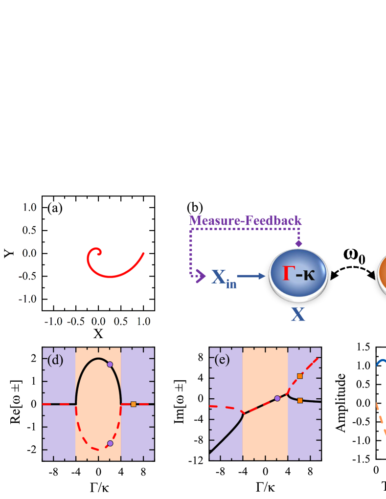
We consider a generic dissipative resonance system, which can be described by the Hamiltonian and the corresponding quantum Langevin equation , where () is the annihilation (creation) operator of the resonance mode, is the resonance frequency, is the amplitude dissipation rate with the associate noise operator being . The quadratures of the resonance mode are defined as and , which correspond to the bases in the phase space. and correspond to the input quadratures. The equations of motion for the quadratures are given by , Because of the dissipation, the evolution trajectory in the phase space is a spiral curve approaching the origin of coordinates, as shown in Fig. 1(a). To construct a -symmetric Hamiltonian, as sketched in Fig. 1(b), we use a feedback loop in which component is measured with the outcome feedback to input component, i.e., , with being the feedback parameter. Then the system dynamics is modified as
| (1) |
In the bases of quadratures with the vector , the equations can be rewritten as with
| (2) |
where is the identity matrix. After dropping the identity matrix term that corresponds to a common gain or loss, the effective Hamiltonian is -symmetric. Here the parity operator is the Pauli operator representing the interchange between the two quadratures, and the time-reversal operator denotes complex conjugation operation. Therefore, the feedback transfers the dissipative resonance system into a -symmetric system, with equal gain and loss in two quadratures of the same resonance mode. The key point is that the feedback breaks the symmetry between the quadratures, and thus the two quadratures of a single resonance mode behave like two different modes with gain and loss. As shown in Fig. 1(b), the effective coupling strength between the quadratures is equal to the resonance frequency , as it is just the energy exchange frequency for different components within the system.
For the Hermitian case without dissipation, the trajectory in the phase space is a closed circle. However, in the -symmetric case, the trajectory is squeezed into a oblique ellipse, as plotted in Fig. 1(c). In this case, the total effect of gain and loss for the quadratures are balanced, but the couplings between and are rescaled as a result of gain and loss, with and . Therefore, the trajectory along direction is squeezed (stretched) by a factor of , resulting in an ellipse with an oblique angle of .
The resultant -symmetric system possesses both -symmetric and -symmetry-broken phases, which can be tuned by the feedback parameter . The eigenvalues of are , whose real (imaginary) parts represent the resonance frequency (dissipation rate) of the eigenmodes. In Fig. 1(d) and (e) we plot the real and imaginary parts of the eigenvalues as functions of feedback parameter . When the feedback is weak (), the real parts of the eigenvalues are opposite to each other while the imaginary parts are equal, and the system is in the -symmetric phase. In this case the time evolutions of the quadratures and are still trigonometric functions, but the phase difference is no longer [Fig. 1(f)], which is a result of the phase advance or lag induced by the effective gain or loss. If the feedback is strong enough (), the eigenvalues are purely imaginary, indicating that the eigenmodes are no longer harmonic modes. Then the amplitude of the quadratures increases exponentially with time, as shown in Fig. 1(g).
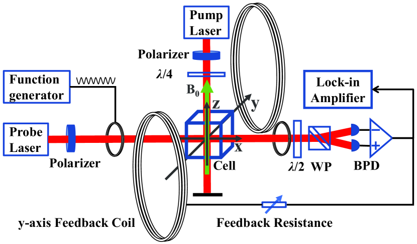
We demonstrate the -symmetric feedback mechanism in a thermal atomic ensemble, which is a typical example of magnetic resonance system. The experimental setup is sketched in Fig. 2. A ensemble of thermal cesium atoms is filled in a vapor cell, and the atoms can be described by a collective spin with spin polarization , where is the spin polarization component along axis. A beam of circularly polarized laser propagating along the direction optically pumps the atomic ensemble to polarize the collective spin. A static magnetic field of is applied along axis, then the collective spin undergoes a Larmor precession around axis, with Larmor frequency being , where is the gyromagnetic ratio of the atom. Thus, the transverse components oscillates in the plane, constituting a harmonic oscillator. We measure the spin polarization component using a probe laser via polarization homodyne detection, and the output signal is then fed into a loop that includes a feedback resistor and the -axis feedback coil, which generates the feedback magnetic field with being the feedback factor. No noise processing of the signal is necessary because the signal-to-noise ratio in our experiments is large enough. In this case the feedback magnetic field carries the information of the spin polarization component , which will result in -symmetric feedback.
When the feedback magnetic field is small compared with the static magnetic field , its effect on can be ignored, and remains equilibrium polarization . Starting from the Bloch equations, we obtain the simplified equations containing only two orthogonal components as
| (3) |
where is the transverse relaxation time. The dynamics can be effectively described by
| (4) |
which is equivalent to Eq. (2) with and . Therefore, the collective spin oscillator constitutes a -symmetric system.
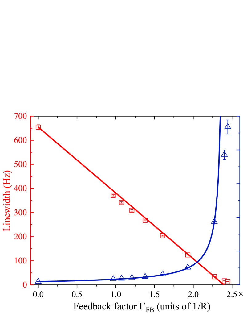
Next we focus on the -symmetric phase () and show the ability of linewidth narrowing. The imaginary part of the eigenvalues is , thus the linewidth is
| (5) |
As the feedback factor increases, the system dissipation keeps reducing, and the resonance linewidth keeps narrowing. In our experiment, the feedback factor is inversely proportional to the feedback resistance . Therefore, our scheme enables flexible adjusting of the linewidth by changing the feedback factor through the resistance .
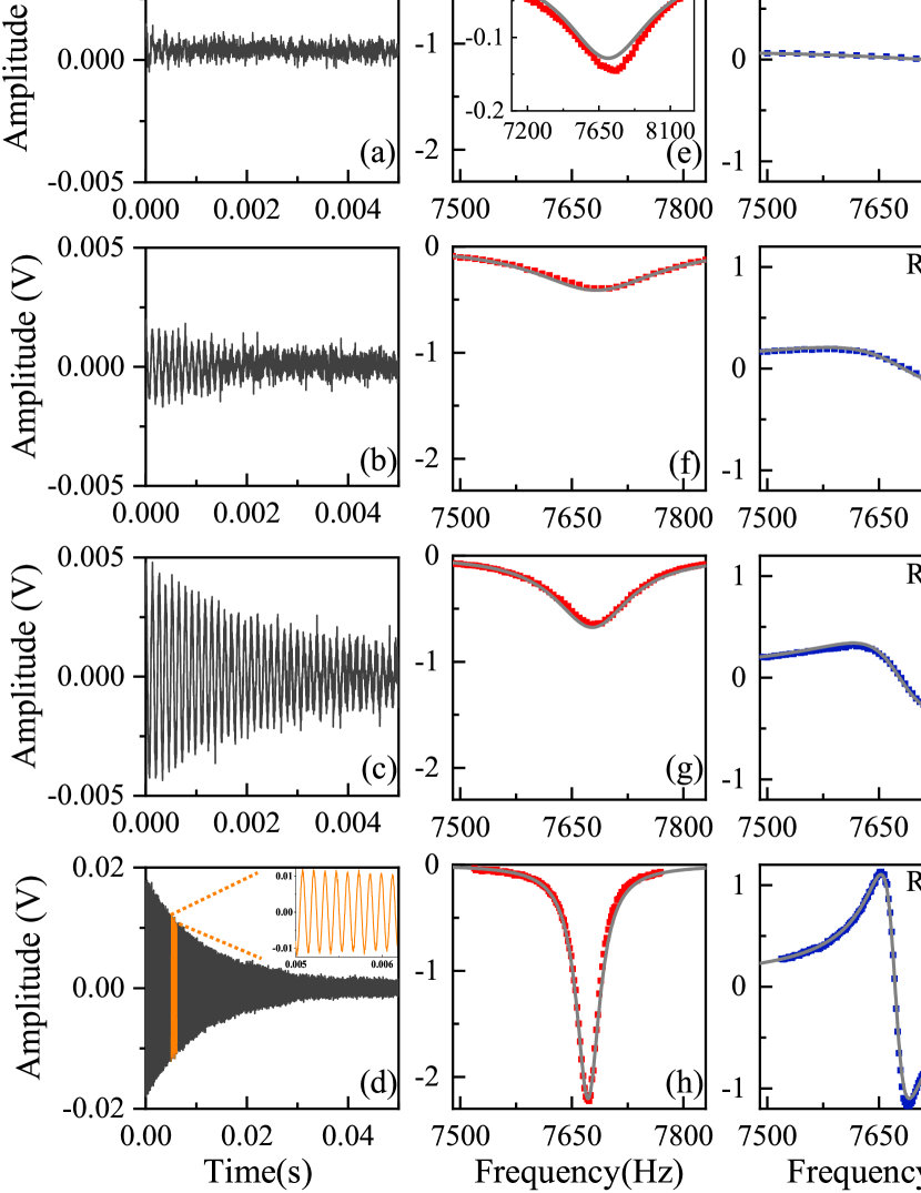
In order to measure the resonance linewidth, we apply a weak driving magnetic field along axis, which corresponds to an additional term in the equation of in Eq. (3). Then the system undergoes forced oscillation, and we can use instantaneous drive with sudden tuning off to obtain the system evolution dynamics in the time domain, or use continuous drive with scanning frequency to obtain the system response in the frequency domain. In Fig. 3, the time domain signals (first column), frequency domain absorption signals (second column) and dispersion signals (third column) are plotted. From top to bottom, as the feedback resistance decreases (corresponding to the increase of the feedback factor ), it shows clearly that the oscillation lasts longer, and the absorption linewidth becomes narrower, and the dispersion slope becomes sharper. The experimental results are in good agreement with the theoretical predictions, where the feedback delay has been taken into account (see Supplemental Material sup ).
The dependencies of linewidth and equivalent relaxation time on the feedback factor are plotted in Fig. 4. In the experiment, we have observed the reduction of the linewidth from to Hz, which is times narrower. The equivalent relaxation time increases from to ms, which significantly extends the coherence time of the system. Further improvement is limited by the stability of the present experimental system, as it becomes more sensitive to the parameter variations when the linewidth is very narrow.
The -symmetric feedback induced linewidth narrowing method holds great potential for high-precision measurements. Our experimental system can be directly used to improve the measurement sensitivity of magnetic field, with the apparatus similar to the magnetometer Groeger et al. (2006); Budker and Kimball (2013). When the driving magnetic field is on resonance with the Larmor frequency , the spin polarization reaches its maximum value. Thus the magnitude of the magnetic field can be obtained by scanning the frequency of the driving magnetic field. The measurement sensitivity of this magnetometer is Groeger et al. (2006); Budker and Kimball (2013); sup
| (6) |
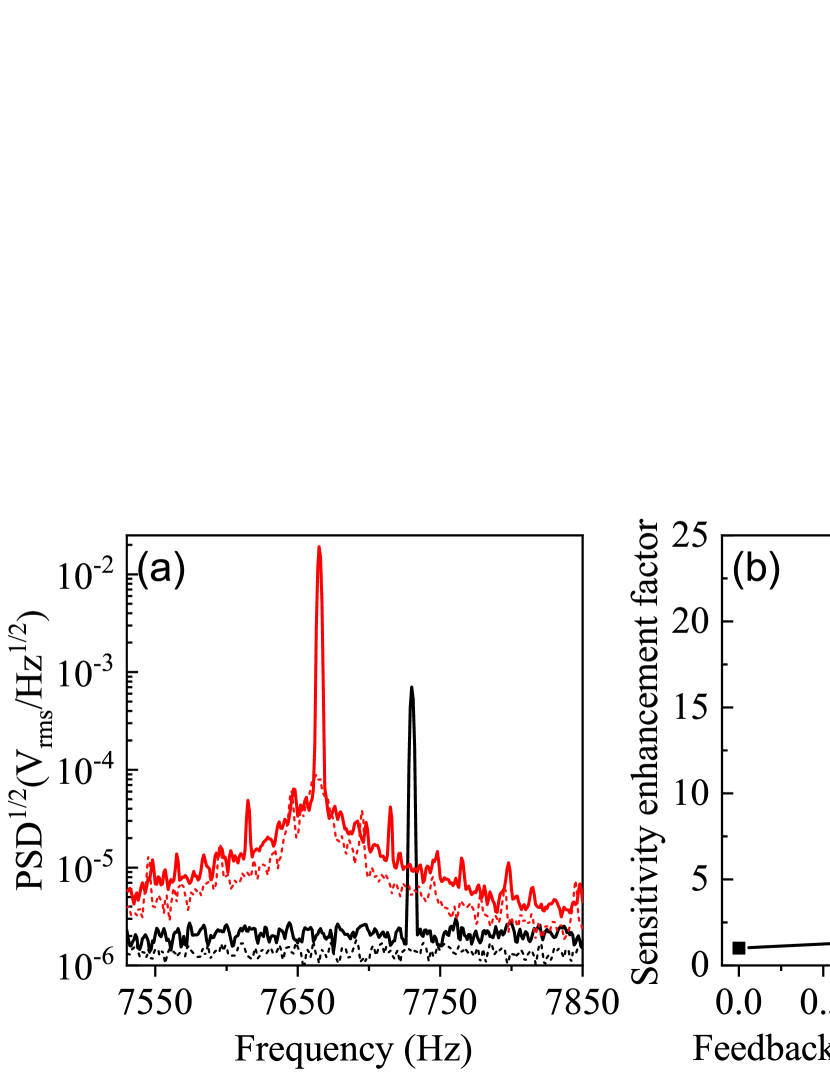
where . To obtain the signal-to-noise ratio , we measure the square root of the power spectral density (PSD1/2) by feeding the output of time domain signals into the fast fourier transformation (FFT) spectrum analyzer (SR760). As compared in Fig. 5(a), the signal with feedback is significantly larger compared to that without feedback. As the background noise also increases, the signal-to-noise ratio stays almost unchanged. The shift of resonance frequency originates from the relaxation and the feedback with delay (see Supplemental Material sup ), which does not affect the measurement sensitivity for small changes of magnetic field. According to Eq. (6), we can obtain the dependence of sensitivity on the feedback factor, as plotted in Fig. 5(b). The sensitivity of the magnetometer is enhanced up to times, with the linewidth narrowing playing a significant role in this enhancement. Compared with the -fold reduction of the linewidth, this -times enhancement of the measurement sensitivity indicates some additional noise in the feedback process, which may be overcome by further stabilizing the feedback loop.
In summary, we propose a -symmetric feedback method in a general dissipative resonance system. By constructing a quadrature measurement-feedback loop in which one quadrature component is measured with feedback, a purely dissipative resonance system can be transformed into a -symmetric system, with tunable -symmetric phase and -symmetry-broken phase. Such a -symmetric system contains only a single resonance mode, without the requirement of two or more modes, as the feedback breaks the symmetry between the quadratures, and thus the two quadratures of a single resonance mode behave like two different modes. The method finds important applications in linewidth narrowing and enhancement of measurement sensitivity. We demonstrate the proposal in a thermal atomic ensemble and observe a -fold narrowing of the magnetic resonance linewidth. By applying the method in the magnetometer, we realize a -times enhancement of the magnetic field measurement sensitivity. It can also be directly applied to other precision measurement experiments limited by linewidth such as atomic gyroscopy. Our study provides a new perspective on using feedback to construct -symmetric systems, which form an excellent platform for studying non-Hermitian physics, with broad applications in high-precision measurement and sensing.
Acknowledgements.
This work is supported by the Key-Area Research and Development Program of Guangdong Province (Grants No. 2019B030330001), the National Natural Science Foundation of China (NSFC) (Grants No. 12275145, No. 92050110, No. 91736106, No. 11674390, and No. 91836302), and the National Key R&D Program of China (Grants No. 2018YFA0306504).References
- Kominis et al. (2003) I. K. Kominis, T. W. Kornack, J. C. Allred, and M. V. Romalis, Nature (London) 422, 596 (2003).
- Budker and Romalis (2007) D. Budker and M. Romalis, Nat. Phys. 3, 227 (2007).
- Kornack et al. (2005) T. W. Kornack, R. K. Ghosh, and M. V. Romalis, Phys. Rev. Lett. 95, 230801 (2005).
- Suefke et al. (2017) M. Suefke, S. Lehmkuhl, A. Liebisch, B. Blümich, and S. Appelt, Nat. Phys. 13, 568 (2017).
- Jiang et al. (2021) M. Jiang, H. Su, A. Garcon, X. Peng, and D. Budker, Nat. Phys. 17, 1402 (2021).
- Afach et al. (2021) S. Afach, B. C. Buchler, D. Budker, C. Dailey, A. Derevianko, V. Dumont, N. L. Figueroa, I. Gerhardt, Z. D. Grujić, H. Guo, et al., Nat. Phys. 17, 1396 (2021).
- Su et al. (2021) H. Su, Y. Wang, M. Jiang, W. Ji, P. Fadeev, D. Hu, X. Peng, and D. Budker, Sci. Adv. 7, eabi9535 (2021).
- Wu (2021) Z. Wu, Rev. Mod. Phys. 93, 035006 (2021).
- Balabas et al. (2010) M. V. Balabas, T. Karaulanov, M. P. Ledbetter, and D. Budker, Phys. Rev. Lett. 105, 070801 (2010).
- Zhao et al. (2008) K. F. Zhao, M. Schaden, and Z. Wu, Phys. Rev. A 78, 034901 (2008).
- Happer and Tang (1973) W. Happer and H. Tang, Phys. Rev. Lett. 31, 273 (1973).
- Allred et al. (2002) J. C. Allred, R. N. Lyman, T. W. Kornack, and M. V. Romalis, Phys. Rev. Lett. 89, 130801 (2002).
- Budker et al. (2002) D. Budker, W. Gawlik, D. F. Kimball, S. M. Rochester, V. V. Yashchuk, and A. Weis, Rev. Mod. Phys. 74, 1153 (2002).
- Scully and Fleischhauer (1992) M. O. Scully and M. Fleischhauer, Phys. Rev. Lett. 69, 1360 (1992).
- Bender and Boettcher (1998) C. M. Bender and S. Boettcher, Phys. Rev. Lett. 80, 5243 (1998).
- Feng et al. (2017) L. Feng, R. El-Ganainy, and L. Ge, Nat. Photonics 11, 752 (2017).
- El-Ganainy et al. (2018) R. El-Ganainy, K. G. Makris, M. Khajavikhan, Z. H. Musslimani, S. Rotter, and D. N. Christodoulides, Nat. Phys. 14, 11 (2018).
- Özdemir et al. (2019) Ş. K. Özdemir, S. Rotter, F. Nori, and L. Yang, Nat. Mater. 18, 783 (2019).
- Makris et al. (2008) K. G. Makris, R. El-Ganainy, D. N. Christodoulides, and Z. H. Musslimani, Phys. Rev. Lett. 100, 103904 (2008).
- Guo et al. (2009) A. Guo, G. J. Salamo, D. Duchesne, R. Morandotti, M. Volatier-Ravat, V. Aimez, G. A. Siviloglou, and D. N. Christodoulides, Phys. Rev. Lett. 103, 093902 (2009).
- Rüter et al. (2010) C. E. Rüter, K. G. Makris, R. El-Ganainy, D. N. Christodoulides, M. Segev, and D. Kip, Nat. Phys. 6, 192 (2010).
- Regensburger et al. (2012) A. Regensburger, C. Bersch, M.-A. Miri, G. Onishchukov, D. N. Christodoulides, and U. Peschel, Nature (London) 488, 167 (2012).
- Chang et al. (2014) L. Chang, X. Jiang, S. Hua, C. Yang, J. Wen, L. Jiang, G. Li, G. Wang, and M. Xiao, Nat. Photonics 8, 524 (2014).
- Peng et al. (2014) B. Peng, Ş. K. Özdemir, F. Lei, F. Monifi, M. Gianfreda, G. L. Long, S. Fan, F. Nori, C. M. Bender, and L. Yang, Nat. Phys. 10, 394 (2014).
- Feng et al. (2014) L. Feng, Z. J. Wong, R.-M. Ma, Y. Wang, and X. Zhang, Science 346, 972 (2014).
- Hang et al. (2013) C. Hang, G. Huang, and V. V. Konotop, Phys. Rev. Lett. 110, 083604 (2013).
- Zhang et al. (2016) Z. Zhang, Y. Zhang, J. Sheng, L. Yang, M.-A. Miri, D. N. Christodoulides, B. He, Y. Zhang, and M. Xiao, Phys. Rev. Lett. 117, 123601 (2016).
- Li et al. (2019) J. Li, A. K. Harter, J. Liu, L. de Melo, Y. N. Joglekar, and L. Luo, Nat. Commun. 10, 855 (2019).
- Ding et al. (2021) L. Ding, K. Shi, Q. Zhang, D. Shen, X. Zhang, and W. Zhang, Phys. Rev. Lett. 126, 083604 (2021).
- Schindler et al. (2011) J. Schindler, A. Li, M. C. Zheng, F. M. Ellis, and T. Kottos, Phys. Rev. A 84, 040101(R) (2011).
- Sun et al. (2014) Y. Sun, W. Tan, H.-q. Li, J. Li, and H. Chen, Phys. Rev. Lett. 112, 143903 (2014).
- Yang et al. (2022) X. Yang, J. Li, Y. Ding, M. Xu, X.-F. Zhu, and J. Zhu, Phys. Rev. Lett. 128, 065701 (2022).
- Wu et al. (2019) Y. Wu, W. Liu, J. Geng, X. Song, X. Ye, C.-K. Duan, X. Rong, and J. Du, Science 364, 878 (2019).
- Jing et al. (2014) H. Jing, S. K. Özdemir, X.-Y. Lü, J. Zhang, L. Yang, and F. Nori, Phys. Rev. Lett. 113, 053604 (2014).
- Lü et al. (2015) X.-Y. Lü, H. Jing, J.-Y. Ma, and Y. Wu, Phys. Rev. Lett. 114, 253601 (2015).
- Xu et al. (2015) X.-W. Xu, Y.-x. Liu, C.-P. Sun, and Y. Li, Phys. Rev. A 92, 013852 (2015).
- Schönleber et al. (2016) D. W. Schönleber, A. Eisfeld, and R. El-Ganainy, New J. Phys. 18, 045014 (2016).
- Zhang et al. (2018) J. Zhang, B. Peng, Ş. K. Özdemir, K. Pichler, D. O. Krimer, G. Zhao, F. Nori, Y.-x. Liu, S. Rotter, and L. Yang, Nat.Photonics 12, 479 (2018).
- Zhu et al. (2014) X. Zhu, H. Ramezani, C. Shi, J. Zhu, and X. Zhang, Phys. Rev. X 4, 031042 (2014).
- Fleury et al. (2015) R. Fleury, D. Sounas, and A. Alù, Nat. Commun. 6, 5905 (2015).
- Bittner et al. (2012) S. Bittner, B. Dietz, U. Günther, H. L. Harney, M. Miski-Oglu, A. Richter, and F. Schäfer, Phys. Rev. Lett. 108, 024101 (2012).
- Hodaei et al. (2017) H. Hodaei, A. U. Hassan, S. Wittek, H. Garcia-Gracia, R. El-Ganainy, D. N. Christodoulides, and M. Khajavikhan, Nature (London) 548, 187 (2017).
- Chen et al. (2017) W. Chen, Ş. Kaya Özdemir, G. Zhao, J. Wiersig, and L. Yang, Nature (London) 548, 192 (2017).
- Lai et al. (2019) Y.-H. Lai, Y.-K. Lu, M.-G. Suh, Z. Yuan, and K. Vahala, Nature (London) 576, 65 (2019).
- Xiao et al. (2019) Z. Xiao, H. Li, T. Kottos, and A. Alù, Phys. Rev. Lett. 123, 213901 (2019).
- Kononchuk et al. (2022) R. Kononchuk, J. Cai, F. Ellis, R. Thevamaran, and T. Kottos, Nature (London) 607, 697 (2022).
- Bechhoefer (2005) J. Bechhoefer, Rev. Mod. Phys. 77, 783 (2005).
- Wiseman (1994) H. M. Wiseman, Phys. Rev. A 49, 2133 (1994).
- Hopkins et al. (2003) A. Hopkins, K. Jacobs, S. Habib, and K. Schwab, Phys. Rev. B 68, 235328 (2003).
- Kleckner and Bouwmeester (2006) D. Kleckner and D. Bouwmeester, Nature (London) 444, 75 (2006).
- Hamerly and Mabuchi (2012) R. Hamerly and H. Mabuchi, Phys. Rev. Lett. 109, 173602 (2012).
- Wilson et al. (2015) D. J. Wilson, V. Sudhir, N. Piro, R. Schilling, A. Ghadimi, and T. J. Kippenberg, Nature (London) 524, 325 (2015).
- Rossi et al. (2017) M. Rossi, N. Kralj, S. Zippilli, R. Natali, A. Borrielli, G. Pandraud, E. Serra, G. Di Giuseppe, and D. Vitali, Phys. Rev. Lett. 119, 123603 (2017).
- Guo et al. (2019) J. Guo, R. Norte, and S. Gröblacher, Phys. Rev. Lett. 123, 223602 (2019).
- Tebbenjohanns et al. (2019) F. Tebbenjohanns, M. Frimmer, A. Militaru, V. Jain, and L. Novotny, Phys. Rev. Lett. 122, 223601 (2019).
- Sommer and Genes (2019) C. Sommer and C. Genes, Phys. Rev. Lett. 123, 203605 (2019).
- van der Laan et al. (2021) F. van der Laan, F. Tebbenjohanns, R. Reimann, J. Vijayan, L. Novotny, and M. Frimmer, Phys. Rev. Lett. 127, 123605 (2021).
- Whittle et al. (2021) C. Whittle, E. D. Hall, S. Dwyer, N. Mavalvala, V. Sudhir, R. Abbott, A. Ananyeva, C. Austin, L. Barsotti, J. Betzwieser, et al., Science 372, 1333 (2021).
-
Schmid et al. (2022)
G.-L. Schmid, C. T. Ngai,
M. Ernzer, M. B. Aguilera, T. M. Karg, and P. Treutlein, Phys.
Rev. X 12, 011020
(2022).
- Koch et al. (2010) M. Koch, C. Sames, A. Kubanek, M. Apel, M. Balbach, A. Ourjoumtsev, P. W. H. Pinkse, and G. Rempe, Phys. Rev. Lett. 105, 173003 (2010).
- Behbood et al. (2013) N. Behbood, G. Colangelo, F. Martin Ciurana, M. Napolitano, R. J. Sewell, and M. W. Mitchell, Phys. Rev. Lett. 111, 103601 (2013).
- Hush et al. (2013) M. R. Hush, S. S. Szigeti, A. R. R. Carvalho, and J. J. Hope, New J. Phys. 15, 113060 (2013).
- Ivanov and Ivanova (2014) D. A. Ivanov and T. Y. Ivanova, J. Phys. B: At. Mol. Opt. Phys. 47, 135303 (2014).
- Schemmer et al. (2017) M. Schemmer, A. Johnson, R. Photopoulos, and I. Bouchoule, Phys. Rev. A 95, 043641 (2017).
- Kopylov et al. (2015) W. Kopylov, C. Emary, E. Schöll, and T. Brandes, New J. Phys. 17, 013040 (2015).
- Hurst and Spielman (2019) H. M. Hurst and I. B. Spielman, Phys. Rev. A 99, 053612 (2019).
- Hurst et al. (2020) H. M. Hurst, S. Guo, and I. B. Spielman, Phys. Rev. Res. 2, 043325 (2020).
- Ivanov et al. (2020) D. A. Ivanov, T. Y. Ivanova, S. F. Caballero-Benitez, and I. B. Mekhov, Phys. Rev. Lett. 124, 010603 (2020).
- Buonaiuto et al. (2021) G. Buonaiuto, F. Carollo, B. Olmos, and I. Lesanovsky, Phys. Rev. Lett. 127, 133601 (2021).
- Munoz-Arias et al. (2020) M. H. Munoz-Arias, I. H. Deutsch, P. S. Jessen, and P. M. Poggi, Phys. Rev. A 102, 022610 (2020).
- Geremia (2006) J. Geremia, Phys. Rev. Lett. 97, 073601 (2006).
- Yanagisawa (2006) M. Yanagisawa, Phys. Rev. Lett. 97, 190201 (2006).
- Negretti et al. (2007) A. Negretti, U. V. Poulsen, and K. Mølmer, Phys. Rev. Lett. 99, 223601 (2007).
- Sayrin et al. (2011) C. Sayrin, I. Dotsenko, X. Zhou, B. Peaudecerf, T. Rybarczyk, S. Gleyzes, P. Rouchon, M. Mirrahimi, H. Amini, M. Brune, J.-M. Raimond, and S. Haroche, Nature (London) 477, 73 (2011).
- Zhou et al. (2012) X. Zhou, I. Dotsenko, B. Peaudecerf, T. Rybarczyk, C. Sayrin, S. Gleyzes, J. M. Raimond, M. Brune, and S. Haroche, Phys. Rev. Lett. 108, 243602 (2012).
- Gajdacz et al. (2016) M. Gajdacz, A. J. Hilliard, M. A. Kristensen, P. L. Pedersen, C. Klempt, J. J. Arlt, and J. F. Sherson, Phys. Rev. Lett. 117, 073604 (2016).
- Lammers et al. (2016) J. Lammers, H. Weimer, and K. Hammerer, Phys. Rev. A 94, 052120 (2016).
- Wu and Eckardt (2022) L.-N. Wu and A. Eckardt, Phys. Rev. Res. 4, L022045 (2022).
- Morrow et al. (2002) N. V. Morrow, S. K. Dutta, and G. Raithel, Phys. Rev. Lett. 88, 093003 (2002).
- Steck et al. (2004) D. A. Steck, K. Jacobs, H. Mabuchi, T. Bhattacharya, and S. Habib, Phys. Rev. Lett. 92, 223004 (2004).
- Vijay et al. (2012) R. Vijay, C. Macklin, D. H. Slichter, S. J. Weber, K. W. Murch, R. Naik, A. N. Korotkov, and I. Siddiqi, Nature (London) 490, 77 (2012).
- Carmele et al. (2013) A. Carmele, J. Kabuss, F. Schulze, S. Reitzenstein, and A. Knorr, Phys. Rev. Lett. 110, 013601 (2013).
- Vanderbruggen et al. (2013) T. Vanderbruggen, R. Kohlhaas, A. Bertoldi, S. Bernon, A. Aspect, A. Landragin, and P. Bouyer, Phys. Rev. Lett. 110, 210503 (2013).
- Kohler et al. (2017) J. Kohler, N. Spethmann, S. Schreppler, and D. M. Stamper-Kurn, Phys. Rev. Lett. 118, 063604 (2017).
- Kroeger et al. (2020) K. Kroeger, N. Dogra, R. Rosa-Medina, M. Paluch, F. Ferri, T. Donner, and T. Esslinger, New J. Phys. 22, 033020 (2020).
- Young et al. (2021) J. T. Young, A. V. Gorshkov, and I. B. Spielman, Phys. Rev. Res. 3, 043075 (2021).
- Jiang et al. (2021) M. Jiang, H. Su, Z. Wu, X. Peng, and D. Budker, Sci. Adv. 7, eabe0719 (2021).
- Lloyd and Slotine (2000) S. Lloyd and J.-J. E. Slotine, Phys. Rev. A 62, 012307 (2000).
- Liu et al. (2013) Z.-P. Liu, H. Wang, J. Zhang, Y.-x. Liu, R.-B. Wu, C.-W. Li, and F. Nori, Phys. Rev. A 88, 063851 (2013).
- Muñoz-Arias et al. (2020) M. H. Muñoz-Arias, P. M. Poggi, P. S. Jessen, and I. H. Deutsch, Phys. Rev. Lett. 124, 110503 (2020).
- Cuairan et al. (2022) M. T. Cuairan, J. Gieseler, N. Meyer, and R. Quidant, Phys. Rev. Lett. 128, 213601 (2022).
- Yamamoto (2016) N. Yamamoto, Phys. Rev. Appl. 5, 044012 (2016).
- Shimazu and Yamamoto (2021) R. Shimazu and N. Yamamoto, Phys. Rev. Appl. 15, 044006 (2021).
- Thomsen et al. (2002) L. K. Thomsen, S. Mancini, and H. M. Wiseman, Phys. Rev. A 65, 061801(R) (2002).
- Inoue et al. (2013) R. Inoue, S.-I.-R. Tanaka, R. Namiki, T. Sagawa, and Y. Takahashi, Phys. Rev. Lett. 110, 163602 (2013).
- Wade et al. (2015) A. C. J. Wade, J. F. Sherson, and K. Mølmer, Phys. Rev. Lett. 115, 060401 (2015).
- Cox et al. (2016) K. C. Cox, G. P. Greve, J. M. Weiner, and J. K. Thompson, Phys. Rev. Lett. 116, 093602 (2016).
- Wang et al. (2005) J. Wang, H. M. Wiseman, and G. J. Milburn, Phys. Rev. A 71, 042309 (2005).
- Carvalho et al. (2008) A. R. R. Carvalho, A. J. S. Reid, and J. J. Hope, Phys. Rev. A 78, 012334 (2008).
- Ristè et al. (2013) D. Ristè, M. Dukalski, C. A. Watson, G. de Lange, M. J. Tiggelman, Y. M. Blanter, K. W. Lehnert, R. N. Schouten, and L. DiCarlo, Nature (London) 502, 350 (2013).
- Sudhir et al. (2017) V. Sudhir, D. J. Wilson, R. Schilling, H. Schütz, S. A. Fedorov, A. H. Ghadimi, A. Nunnenkamp, and T. J. Kippenberg, Phys. Rev. X 7, 011001 (2017).
- (102) See Supplemental Material for the theoretical model of feedback with delay, the PT-symmetric feedback in the optical cavity, and experimental details. .
- Groeger et al. (2006) S. Groeger, G. Bison, J.-L. Schenker, R. Wynands, and A. Weis, Eur. Phys. J. D 38, 239 (2006).
- Budker and Kimball (2013) D. Budker and D. F. J. Kimball, eds., Optical Magnetometry (Cambridge University Press, 2013).