2023
[2]\fnmDana \surWeinstein
1]\orgdivKilby Labs, \orgnameTexas Instruments, \orgaddress\cityDallas, \stateTX, \countryUSA 2]\orgdivDepartment of Electrical and Computer Engineering, \orgnamePurdue University, \orgaddress\cityWest Lafayette, \stateIN, \countryUSA
Large-Signal Behavior of Ferroelectric Micro-Electromechanical Transducers
Abstract
CMOS-MEMS resonators seamlessly integrated in advanced integrated circuit (IC) technology have the unique capability to enable unprecedented integration of stable frequency references, acoustic spectral processors, and physical sensors. Demonstrations of transducers leveraging piezoelectric properties of emerging ferroelectric materials such as Hafnium Zirconium Oxide (HZO) and Aluminum Scandium Nitride (AlScN) enable high figure of merit (FOM ) resonators over a wide range of frequencies. CMOS-integrated ferroelectric transducers using a thickness-scaled variant of these films for low voltage operation are feasible by leveraging advancements in ferroelectric random access memory (FRAM) and ferroelectric field effect transistors (FeFETs). However, until now, there has not been a full treatment of the effects of nonlinear large-signal behaviour on the performance of electromechanical systems built using ferroelectric transducers in the low coercive voltage regime. In this work, CMOS-MEMS resonators in a 130 nm process operating at 700 MHz have been used as a vehicle for understanding the performance impact of nonlinear piezoelectric transduction on frequency references and acoustic filters. The first nonlinear large signal model for such resonators has been developed and employed to extract the nonlinear characteristics over different biasing and applied power. Operating conditions and design guidelines have also been developed for these applications, which can be extended to all resonators of this class. The crystallized understanding of large-signal operation of ferroelectric transducers presented in this work provides opportunities to design and demonstrate new capabilities of electromechanical devices in monolithic CMOS-MEMS platforms.
1 Introduction
Realization of monolithic MEMS components in advanced Complementary Metal Oxide Semiconductor (CMOS) IC manufacturing technology has the potential to enable new paradigms in next-generation communications, Internet of Things (IoT), and hardware security. Additional functionality pertaining to Radio Frequency (RF) systems and physical sensing with significant power, area, and cost advantages can be enabled in standard CMOS and emerging 3D heterogeneously integrated (3DHI) IC technology with minor or no modifications to manufacturing and packaging. The emergence of such monolithic solutions is timely in the face of enhanced pressure to integrate and shrink RF front-end module components Aigner20193G4 for current and future generation wireless communication (xG) standards. This challenge, caused by the introduction of new bands and filter-intensive techniques such as Carrier Aggregation (CA) and Multiple Input Multiple Output (MIMO) Fattinger2016CarrierAA , is further exacerbated by a need for configurability. Current Surface Acoustic Wave (SAW) and Bulk Acoustic Wave (BAW) filters RFfilters1 ; RFfilters2 ; RFfilters3 ; RFfilters4 , due to their lack of configurability and requirement of specialized fabrication and packaging, are not suitable in this scenario. Barium Strontium Titanate (BST) Film Bulk Acoustic Resonators (FBARs) ZolfagharlooKoohi2020ReconfigurableRE ; BST_FBAR provide configurable filters due to their ferroelectric properties, but are not CMOS compatible. Intrinsically-switchable ferroelectric-transduced acoustic wave devices in commercial CMOS processes are well poised to address these problems through the elimination of RF switches from font-end modules and monolithic integration. Additionally, autonomous adaptive radio front ends capable of re-configuring their performance characteristics based on the level of the incoming signal can potentially be realized using ferroelectric transduction based MEMS resonators. Ferroelectric devices are currently also a subject of active research for use in neuromorphic compute paradigms to overcome the von Neumann bottleneck Ni2020FerroelectricsFM ; Liu2022ReconfigurableCO ; Dutta2020Monolithic3I ; Han2022FerroelectricDF . These ferroelectric-based solutions consist of hardware based on Spiking Neural Networks (SNNs) Peng2019NanocrystalEmbeddedInsulatorF or Convolutional Neural Networks (CNNs) Kim2022CMOScompatibleCA that leverage the innate capability of the underlying devices to perform storage and processing simultaneously resulting in implementation possibilities such as in-sensor computation Wan2022InSensorCM ; Datta2022InSensorN ; Zhu2021RecentAI . Moreover, on-chip high frequency ultrasound generation through the use of CMOS-integrated BEOL ferroelectric transducers enables applications such as fingerprint detection USfingerprint , high-resolution clinical imaging Fei2016UltrahighF , laser-free picosecond ultrasonics for thin film metrology Matsuda2015FundamentalsOP , and neuromodulation Balasubramanian2020GHzUC , most of which have so far never been implemented in scalable IC manufacturing technologies. All of the aforementioned applications require the application of large signal drive to the transducer elements. Therefore, for the appropriate design of actuators and physical sensors using this technology an understanding of the large signal behavior of integrated ferroelectric transducers is required.
Switchable MEMS resonators based on ferroelectric transduction are currently the subjects of active research tharpe_173_2022 ; Ghatge2019AnUI ; ghatge_nano-mechanical_2018 ; ghatge_non-reciprocal_2019 ; ghatge_30-nm_2020 ; tharpe_-plane_2021 ; hakim_ferroelectric–si_2021 ; AlScN_Rassay ; Wang2020AFB ; wang_high-temperature_2022 spurred by the demonstration of ferroelectricity in back-end-of-line (BEOL)/front-end-of-line (FEOL) compatible materials such as doped Hafnium Dioxide (HfO2)boescke_ferroelectricity_2011 ; polakowski_ferroelectricity_2015 ; HfO2_Mller2015FerroelectricHO ; HfO2_Park2021BinaryFO ; HfO2_Schroeder2022TheFA and AlScN fichtner_ferroelectricity_2020 ; fichtner_alscn_2019 . However, with unique packaging and fabrication considerations, such resonant devices are yet to be monolithically integrated into a CMOS platform. Unreleased resonators incorporated in commercial CMOS with no post-processing have previously been demonstrated Radhika_UnreleasedRes32nm ; bahr_monolithically_2016 ; bahr_32ghz_2018 ; bahr_theory_2015 ; he_tunable_2020 ; he_ferroelectric_2018 ; he_switchable_2019 . Out of these, one class he_ferroelectric_2018 ; he_switchable_2019 ; he_tunable_2020 makes use of switchable piezoelectric transduction with Lead Zirconate Titanate (PZT) ferroelectric capacitors (FeCAPs) integrated in the BEOL of the HPE035 130 nm CMOS FRAM process from Texas Instruments HPE035_McAdams2004A6E ; HPE035_Udayakumar2005IntegrationAB . These high-Q FeCAP-based devices are prime candidates for monolithically integrated intrinsically switchable RF filters and low phase-noise frequency references.
Acoustic wave filters for the transmit path (TX) in RF front-ends encounter high power signals from the RF power amplifier (PA). Moreover, filter nonlinearity can give rise to the generation of harmonics and intermodulation products affecting the performance of the receiver chain (RX). In frequency references, nonlinearity in the frequency filtering resonant element degrades the phase noise. Additionally, for transducers in physical sensing, large displacement/momentum generation is required for high sensitivity which is typically accomplished through large signal drive. Since CMOS integrated ferroelectric resonators are being considered for these applications, analysing the effect of large signal swings and nonlinearity on the analog performance of ferroelectric transducers originally purposed for digital FRAM is paramount. The FeCAP resonant devices discussed in this work have previously only been investigated under a very limited range of operating conditions. In this article, we report on the large signal and temperature-dependent characteristics of CMOS-MEMS ferroelectric resonators. The analysis and conclusions presented have direct implications for acoustic spectral processing, oscillatory systems and physical sensors making use of ferroelectric transducers using current and upcoming materials (such as HZO) for CMOS FRAM FRAM_Mikolajick2020ThePT ; FRAM_BEOL and FeFET applications Khan2020TheFO ; FeFET1_8268425 ; FeFET2 . This work is not limited to transducers integrated in System-in-Package (SiP), but also informs the design and analysis of standalone ferroelectric transducers.
2 Device Design and Acoustic Dispersion
The resonator fabricated in the HPE035 130 nm CMOS process HPE035_TI_FeRAM from Texas Instruments, consists of a phononic waveguide grating formed using an array of BEOL PZT FeCAPs as shown in Fig.1(a). Each unit cell of the waveguide consists of a 70 nm thick ferroelectric PZT capacitor contacted with Iridium (Ir) and conductive Iridium Oxide (IrO2) electrodes. Tungsten (W) vias are used to connect the FeCAP cell to BEOL Cu routing and FEOL Polysilicon (Si) shield. The repetition of these unit cells along the x-direction (lattice constant m) leads to the creation of a slow wave structure in which acoustic waves have a slower velocity of propagation as compared to the BEOL dielectric and the Si substrate underneath. Fig.1(c) shows the fabricated 108 m by 7 m FeCAP waveguide resonator cavity and metal routing to the signal and ground probe pads. To obtain the dispersion characteristics and mode coupling behaviour of the resulting phononic waveguide in terms of the transadmittance , Floquet Periodic Boundary Conditions (PBCs) are utilized in frequency domain analysis with periodic electrical excitation. Detuning the wave-vector by an amount (both real an imaginary) along the path of the Irreducible Brillouin Zone (IBZ) gives propagation and stopband characteristics shown in Fig.1(b). The wave vector corresponds to a phase shift of 180o across the unit cell.
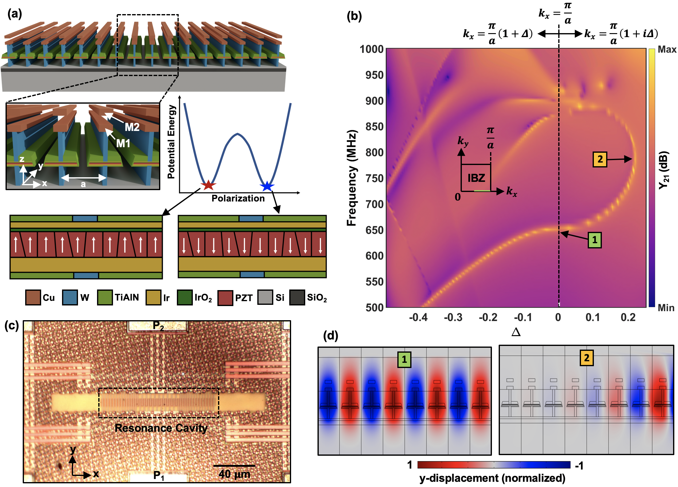
From the dispersion characteristics it is evident that guided mode 1 is capable of propagating in the slow-wave region with a grating-confined mode shape as shown in Fig.1(d). Additionally, the frequency space indicates that no modes exist which can be detected electrically and driven efficiently in the waveguide in the immediate vicinity of Mode 1. This is relevant from the perspective of non-degenerate mode-coupling under large signal excitation of the resonance cavity (modecoupling1_8672780, ) since it could lead to parametric effects such as mechanical domain frequency comb generation in CMOS. Identification of modes from the dispersion analysis that can be electrically excited and detected also informs the design of the high-Q resonance cavity. The resonance cavity is formed by termination of the grating, which introduces reflections. To minimize scattering of acoustic waves, we implement waveguide termination rather than an abrupt transition, in which evanescent Mode 2 (Fig.1(d)) in the termination waveguides is chosen with lattice constant so as to match the resonance frequency of Mode 1 in the cavity. The number of BEOL metal layers in the waveguide unit cell is restricted to two (M1 and M2) and the lateral dimensions are optimized to maximize the stress localization in the PZT thereby increasing the transduction efficiency. In the device discussed in this work, lateral acoustic confinement in the direction is obtained by adding electrically disconnected dummy FeCAP unit cells to either side of the waveguide cavity so that acoustic scattering to the bulk occurs away from the transducer region.
3 Large Signal Performance Analysis
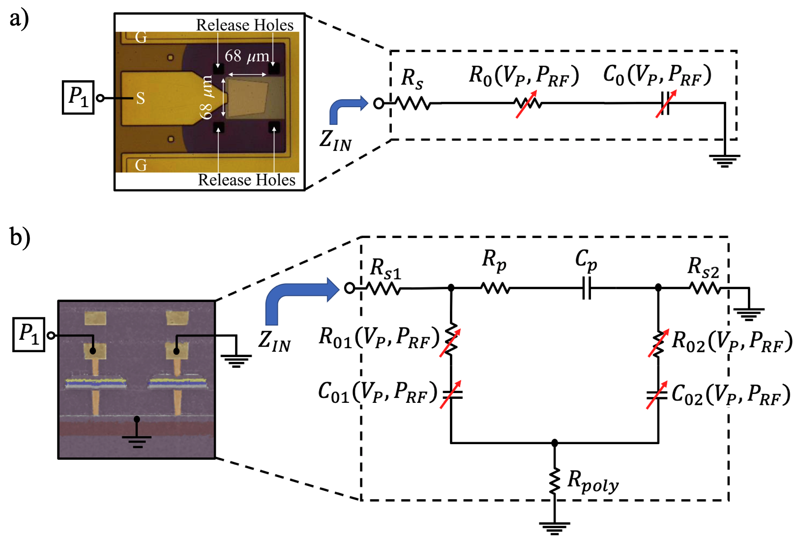
Small-signal RF measurements across different biasing conditions as described in the Supplemental Information section 6.3 show significant variation in the device response with applied bias . Conventional modified Butterworth-Van-Dyke (mBVD) modelling methods MBVD1_Larson2000ModifiedBD ; MBVD2_Bjurstrom2004AnAD ; MBVD3_Campanella2007AutomatedOC ; MBVD4_Campanella2007InstantaneousDO ; MBVD5_Erbes2014HighfrequencyPM are not applicable for the FeCAP resonator performance extraction. This is primarily due to loss in modeling accuracy arising from insufficient circuit elements required to capture the observed characteristics. An augmented mBVD model as depicted in Fig.2(a) has therefore been used to accurately capture the resonator dependence on RF power () and biasing (). The motional branch representing Mode 1 is comprised of the motional resistance , inductance , and capacitance , which are related through the mechanical resonance frequency (angular frequency ) and unloaded quality factor . The physical origin of key parasitic elements in the resonator model is illustrated in Fig.2(b). FeCAP electrical loss elements and are introduced in series with the corresponding intrinsic transducer capacitances and . These losses, just like the capacitances themselves, are dependent on bias and RF power. The series combination of and captures the inter-finger capacitance and associated dielectric loss of the BEOL dielectric, and is considered invariant to bias and RF power. Meanwhile, is included to model the resistance of the grounded polysilicon shield underneath the resonator structure connecting the bottom electrode of all ferroelectric transducers in the array.
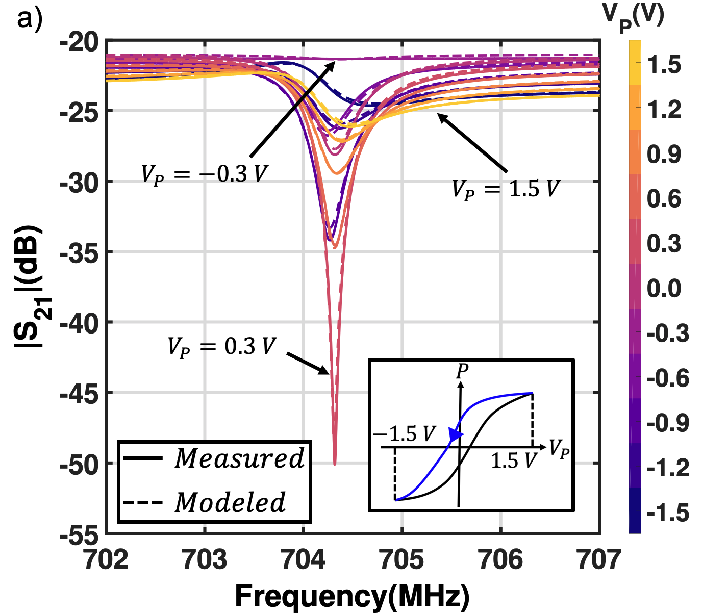
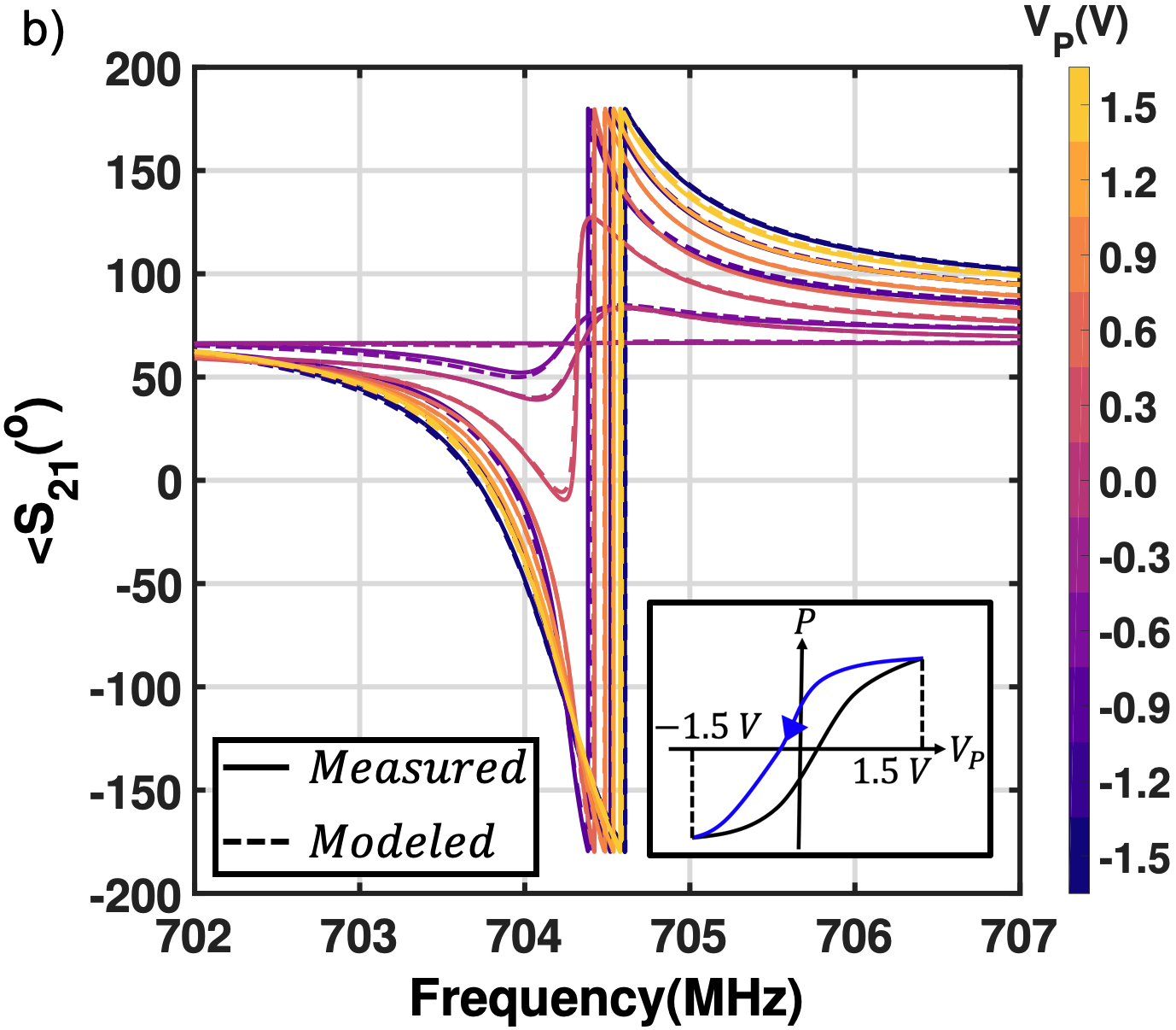
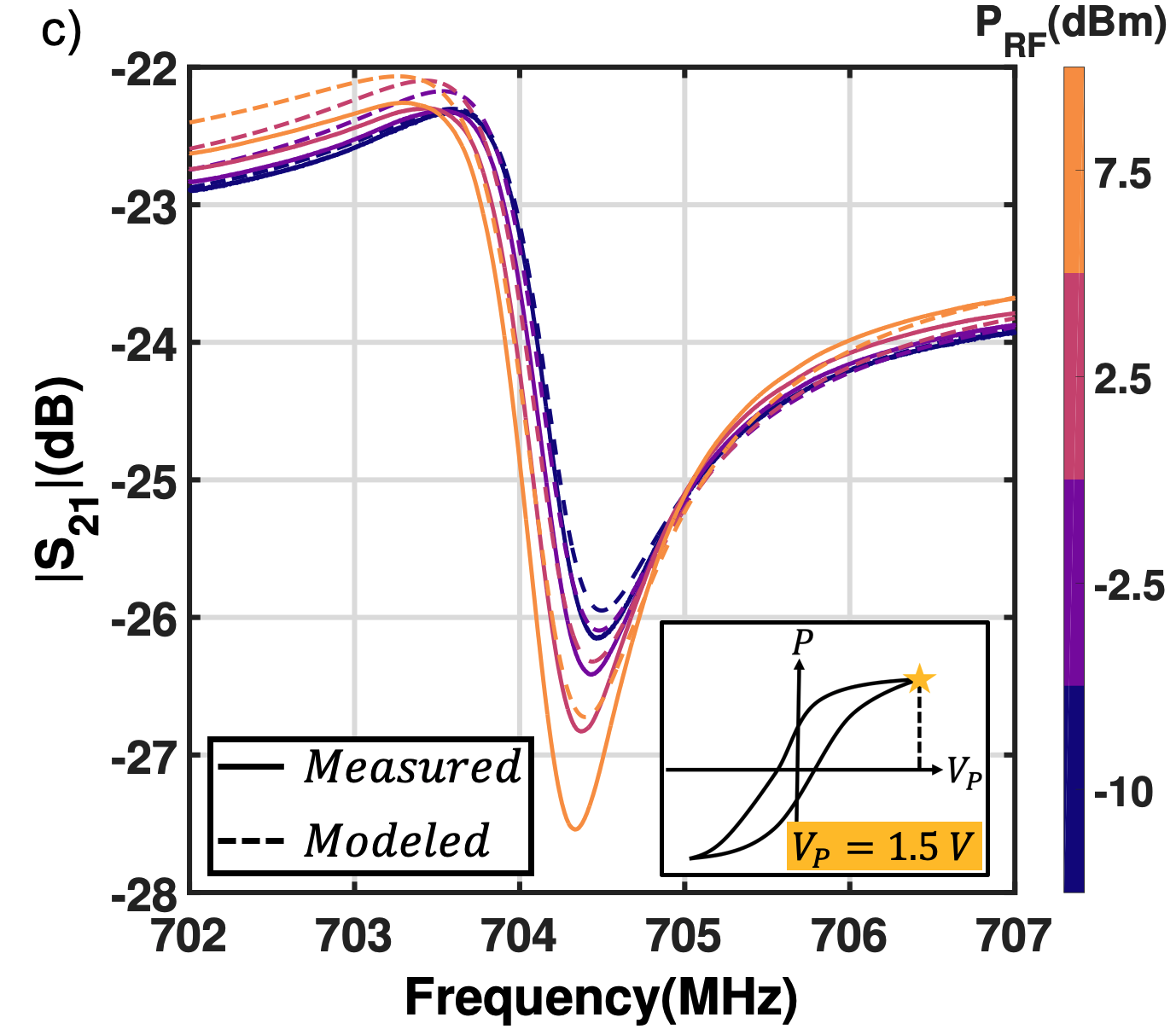
Fig.2(c) clarifies the operating conditions under which the device is characterized. The resonator is biased at a polarization state (as indicated by the star in Fig.2(c)) using voltage superimposed with RF excitation voltage corresponding to different . Under large-signal excitation, the polarization does not follow the characteristics typically seen when the FRAM is digitally switched between two states LSPZT2_Damjanovic1999CONTRIBUTIONSTT ; LSPZT3_Taylor1998DomainWP ; LSPZT4_Taylor1999NonlinearCT ; LSPZT5_Gerber2004EffectsOF ; LSPZT6_Zhang1988DomainWE ; LSPZT7_Hall1998FieldAT . Increasing causes an increase in the average slope and area of the loop corresponding to each value. This can be attributed to loss arising from an increase in the irreversible domain wall motion as the large signal excursions are increased around the pinning voltage .
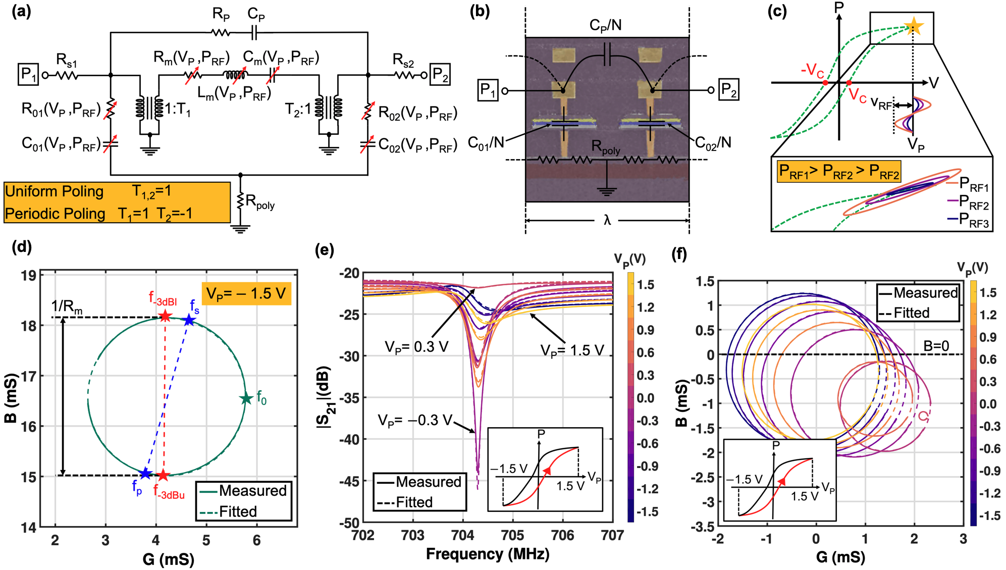
The measured transmission characteristics of the device at -10 dBm and varying as seen in Fig.2(e) show resonance at approximately 704.1 MHz which corresponds to the mechanical resonance frequency . The series resonance peak diminishes as moves from saturation towards the coercive voltage owing to an increase in the motional resistance (as evidenced by the reduction in admittance circle radii of Fig.2)(f)). Due to change in transducer capacitances and , there is a change in the relative magnitudes of electrical feedthrough current between the two ports and the motional current (brought about by corresponding variation in transducer electromechanical coupling). This results in variation in the resonator transfer function as detailed in he_switchable_2019 ; PZTres_Bedair2011HighRT with a high-rejection parallel resonance obtained at = -0.3 V corresponding to mutual cancellation of and . In this particular device, the low amplitude of the series resonance is attributed to the uniform poling of alternate ferroelectric capacitors at the same bias voltage. As detailed in he_switchable_2019 , on the application of alternate poling voltages of opposing polarity to adjacent capacitors, the motional current dominates the feedthrough current resulting in a prominent series resonance. The fundamental mechanical Q-factor of the device is invariant to this poling condition. The parallel resonance under uniform poling shows maximum dependence on since transducer capacitance is strongly dependent on the applied bias which in turn modifies . Admittance circle methodology (supplemental information section 6.2) is used to extract augmented mBVD circuit parameters from measurement. Fig.2(d) shows the Nyquist plot and the corresponding admittance circle fit to measured data for -10 dBm and = -1.5 V. Mechanical resonance frequency , unloaded quality factor and the motional parameters are obtained for all and combinations.
Illustrated in Fig.2(c), levels of -10,-2.5,2.5 and 7.5 dBm are applied to the resonator at different biasing conditions () along the static loop. The resonator , , and effective coupling coefficient are then extracted using the augmented mBVD model for each of these operating points. From the extracted characteristics in Fig.3(a) for of 1.5, 1.2 and 0.9 V, we observe a reduction of 9.39%, 12.92%, and 18.65% respectively for increasing from -10 dBm to 7.5 dBm. Due to larger availability of switchable domains away from saturation, the extrinsic effects Li1991THEEN_extrinsic in the FeCAP transducer increase resulting in stronger nonlinearity in . Additionally, reduces with increasing (Fig.3(c)) associated with an increase in irreversible domain wall motion caused by domain wall pinning revirrev2_Bolten1999ReversibleAI ; revirrev1_Bolten2002ReversibleAI at defect locations. This loss mechanism is prevalent in soft PZT used in FRAM. The increase in extrinsic ferroelastic effects also leads to an increase in the effective coupling coefficient of the resonator with as seen in Fig.3(c). Non-180o domain walls are ferroelastically active and contribute 60-70 of the piezomodulii Li1991THEEN_extrinsic ; increasing the strength of the applied fields results in an increase in the motion of these domain walls, resulting in the cumulative increase in .
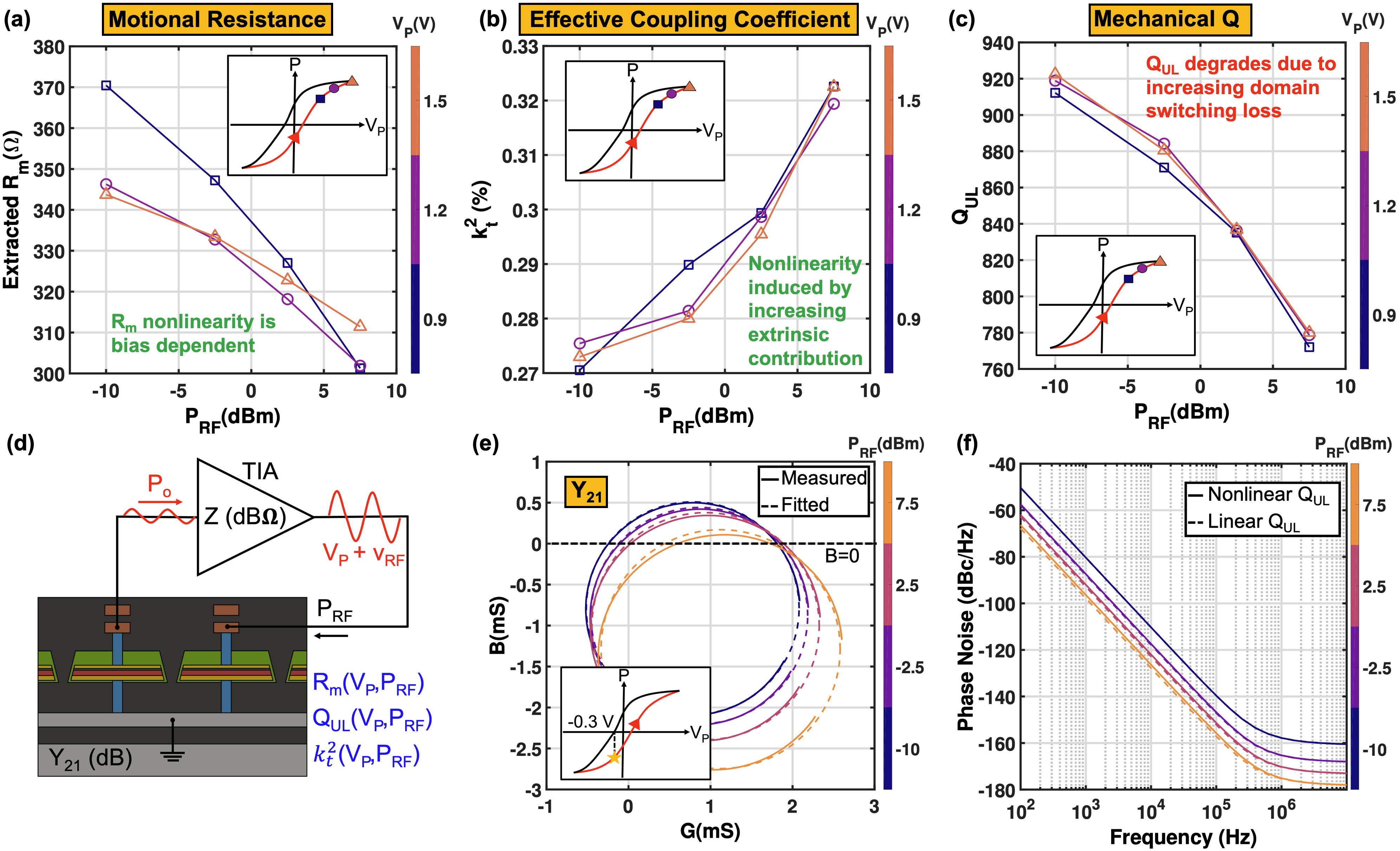
From the perspective of monolithic CMOS-MEMS oscillator design, the FeCAP resonator would generally be connected in the feedback path of a Transimpedance Amplifier (TIA) as shown in Fig.3(d) to form a closed loop. The admittance circles (such as those in Fig.3(e) and (f)) determine whether the phase condition for oscillation is met. For sustained oscillations, the loop gain should be greater than 1 and the circle should intersect the susceptance =0 line. Some admittance circles in Fig.2(f) lie completely below =0, implying that it is not possible to obtain sustained oscillations at these bias voltages. For certain biasing points away from saturation such as =-0.3 V in Fig.3(f), increasing can cause the circle to move below at which point oscillations are not possible.
The oscillator phase noise is given by the Leeson’s equationPhaseNoise_Lavasani2007A5L :
| (1) |
where is the frequency of oscillation, is the frequency offset, is a constant related to the noise corner, F is the noise figure of the TIA and is the oscillation power. For phase noise comparison, it is assumed that the TIA has zero input and output resistance, such that . Since the phase noise in the region depends on , increasing reduces the phase noise at a slightly lower rate relative to the hypothetical case of a power-independent . Fig.3(f) shows a comparison of simulated phase noise of an FeCAP CMOS-MEMS oscillator with and without power-dependent nonlinearity in the resonator. For = 1.5 V, power nonlinearity increases the phase noise at 1 kHz offset from carrier by 1.45 dB at 7.5 dBm RF power, assuming is constant in both cases. Meanwhile, degradation in oscillator phase noise due to reduction with oscillation power is not substantial even for powers as high as 7.5 dBm, indicating viability of higher power operation limited instead by effects such as breakdown and fatigue in the ferroelectric material. The nonlinearity in the ferroelectric resonators gives rise to additional noise up-conversion near the carrier frequency requiring mitigation such as Automatic Gain Control (AGC) AGC_1269438 . Furthermore, due to an increase in close to the coercive voltage as seen in the Y11 circle diameter in Fig.2(f), operating at these biasing conditions would require higher gain from the TIA and hence higher power consumption.
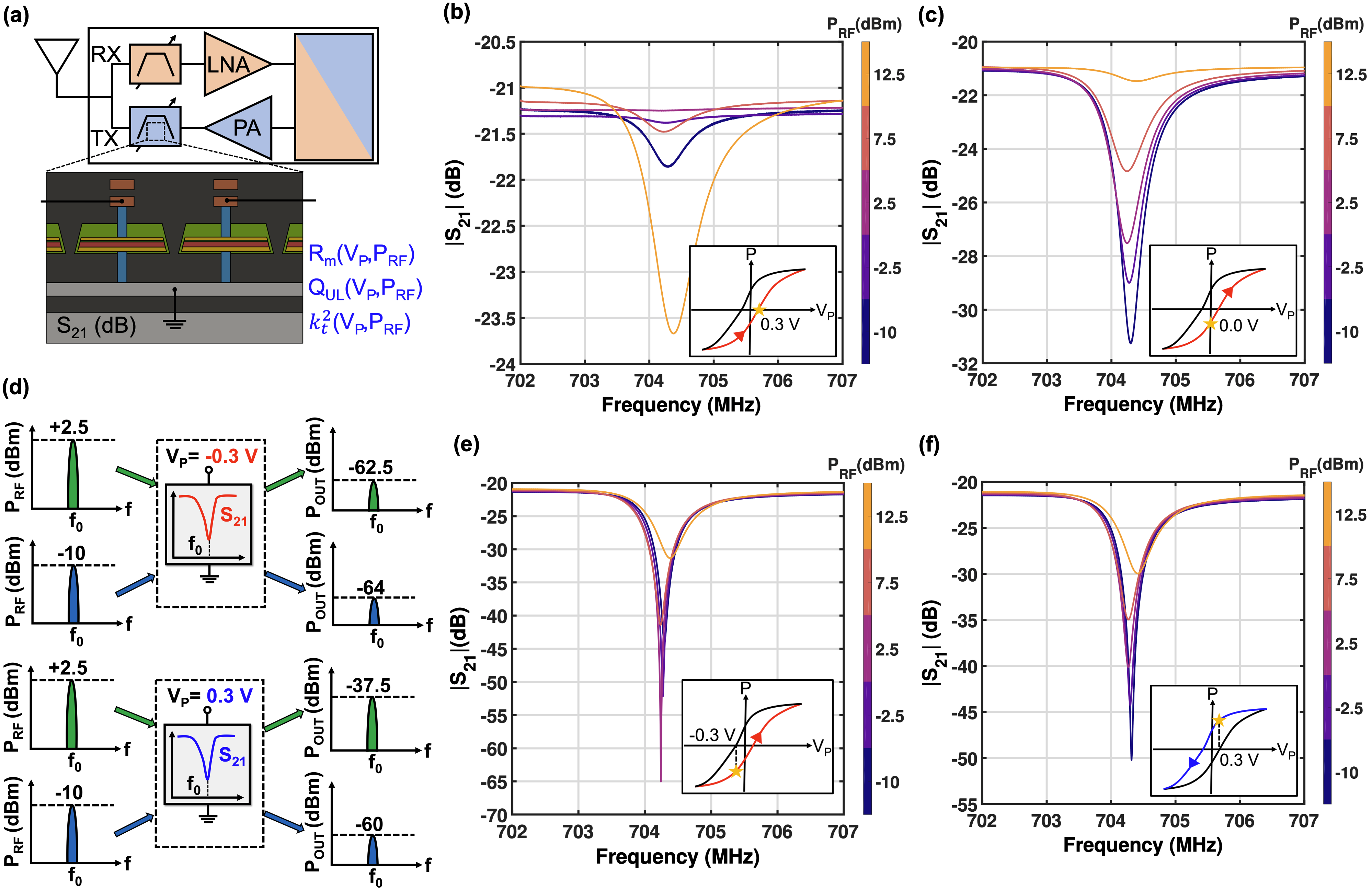
For RF front end applications, switchable multiplexers using FeCAP resonators can be monolithically integrated side by side with Low Noise Amplifiers (LNAs), Power Amplifiers (PAs), and other transmit and receive chain electronics for ultimate miniaturization (Fig.4(a)). However, the power handling and linearity of the FeCAP devices at the heart of the filters interfacing with the antenna and the amplifiers must be considered. From the perspective of switching capability, the resonators are expected to exhibit no electromechanical response when biased at the coercive voltage of the ferroelectric transducers. In this case, when the resonators are biased at the coercive voltage extracted from the static loop =0.3 V, it is observed that the response nullification depends on (Fig.4(b)). As RF power increases, the domain wall motion and switching increase causing a -dependent nullification in the response. As an example, Fig.4(b) shows the response nullification for a of 0.3 V and of 2.5 dBm. FeCAP filter switching is therefore dependent on the signal level; to ensure effective filter switching the bias would need to be adjusted according to the signal level. As an example, when the device is switched off for an input power of 12.5 dBm, = 0 V must be applied as depicted in Fig.4(c).
Modern concurrent wireless communication standards necessitate rejection of blocker signals with levels as high as 0 dBm, which can saturate receivers. Previous implementations of tunable bandstop or notch filters are area-intensive and primarily based on either low-loss substrate waveguides tunableNotch2 ; tunableNotch3 or integrated passive devices (IPDs) on Silicon tunableNotch1 coupled with RF MEMS elements. It has previously been suggested that the sharp parallel resonance notches common to many piezoelectrically and electrostatically transduced resonators can be utilized for blocker rejection in RF front ends PZTres_Bedair2011HighRT . However, the FeCAP resonators in this work are uniquely capable of being used for blocker rejection in monolithic CMOS-MEMS RF front ends. The parallel resonance notch in the FeCAP resonators is most pronounced when biased at of 0.3 V or -0.3 V as shown in Fig.4(d) and (e) with rejection levels as high as 43 dB for the latter. From the transmission response of the resonator for these two biasing conditions in Fig.4(d) and (e), it can be seen that the notch depth varies with the input power level. Therefore, as the blocker signal level at the notch frequency changes from -10 to 2.5 dBm, the corresponding suppression (notch depth) changes from 28 to 18 dB with the FeCAP resonator biased at 0.3 V. Just as in the case of filter switching, adaptive biasing is required to reject the blocker based on its strength owing to the -dependent cancellation of motional and feedthrough currents.
For filters interfaced with the LNA and the PA, the insertion loss (IL) and out-of-band (OOB) rejection are governed by the Q of the resonators comprising the filters RFfilters2 . FeCAP resonator Q must therefore be maximized for IL and OOB rejection. However, from Fig.3(b) we see that resonator Q reduces with increasing . This means that a TX FeCAP resonator-based filter driven by the high from the PA would experience degraded IL and OOB rejection as compared to the RX filter. This in turn requires an increase in current in the PA to compensate for the added loss, which is detrimental for system power consumption. Additionally, considering that transmitters in modern RF systems have very strict emission requirements, modifications to the filter passband edges due to dependent nonlinearity of resonator (Fig.3(c)) places strict restrictions on the amount of power that can be delivered to the antenna.
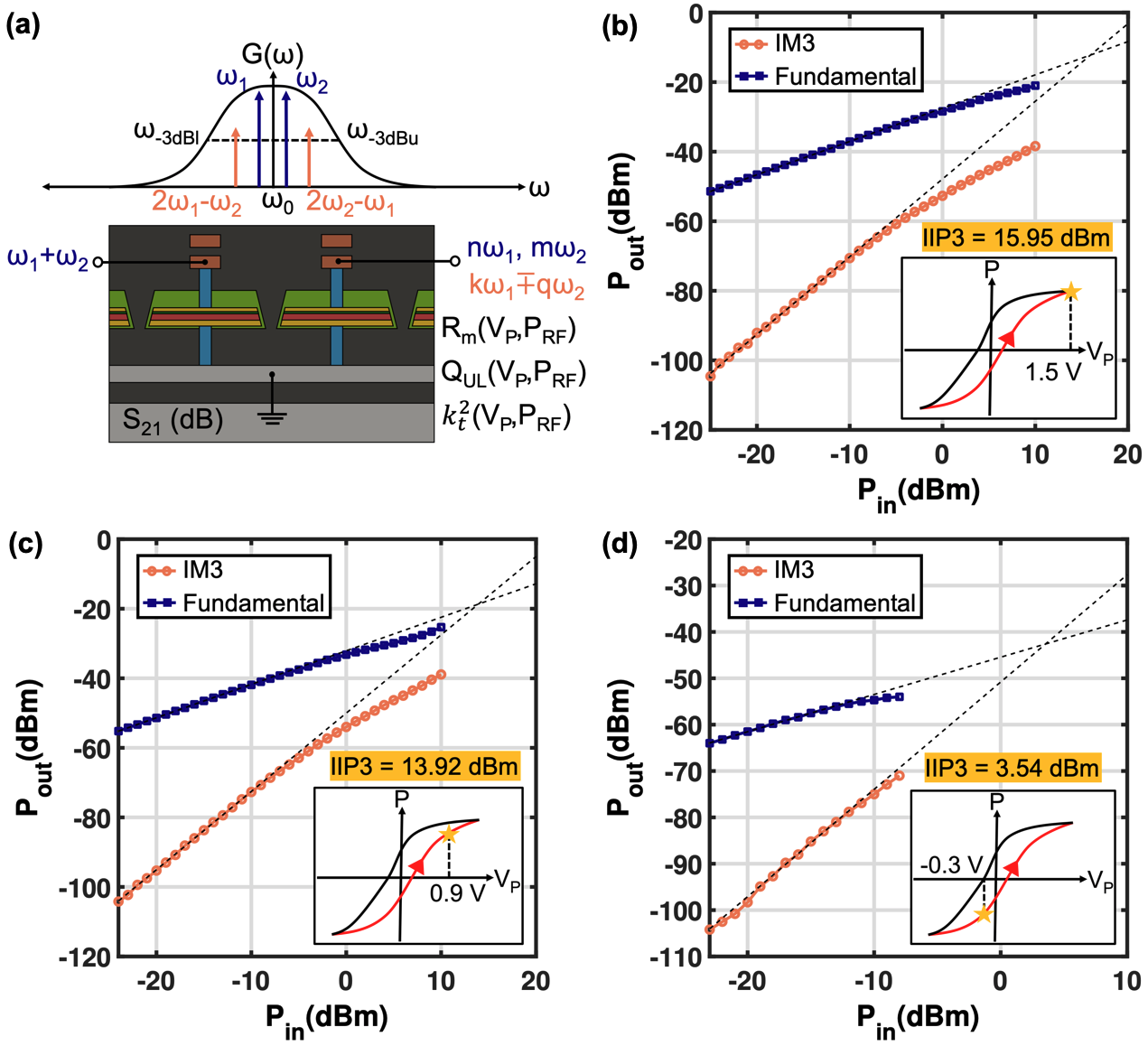
Another aspect associated with the nonlinearity of the FeCAP resonators is the generation of harmonics and intermodulation products in the filters designed using these devices. Generation of such byproducts due to device nonlinearity is highly problematic for the receiver signal chain. To compare the nonlinearity at different biasing conditions, the resonator is characterized for the third order intercept point (IIP3) at three different values of 1.5 V, 0.9 V and -0.3 V. Two fundamental tones and spaced 50 kHz apart from the resonance frequency are applied to the biased resonator and the third order intermodulation component (IM3) levels at and are recorded as shown in Fig.5(a). As can be seen from Fig.5(b), (c) and (d) the device exhibits IIP3 of 15.95 dBm, 13.92 dBm and 3.54 dBm for of 1.5, 0.9 and -0.3 V, respectively. The reduction in IIP3 with bias can be attributed to a shift away from the relatively linear saturation region where less domains are available for switching to the highly nonlinear region where the extrinsic ferroelectric characteristics are more pronounced. Thus, resonators biased in the off-state (= 0 V) and bandstop () configurations can exhibit harmonic and IM product generation which must be considered when designing filters using ferroelectric transducers. Device linearity can be improved significantly by utilizing resonator cascading techniques as demonstrated in linearityImprovement opening opportunities for monolithic CMOS-MEMS RF front ends. On the other hand, the inherent nonlinearity and hysteresis of the ferroelectric electromechanical transducers can be exploited for autonomous adaptive radio front ends capable of tailoring their transfer functions depending on the input signal level. In RF sampling systems that make use of low dynamic range wide-band Analog-to-Digital Converters (ADCs), there is a need for cancellation of signals arising out of both internal spurs as well as external interferers. In all such applications the number of control inputs for the required re-configurable filters would be extremely large. Therefore, the signal-level dependent nonlinear behaviour of FeCAP resonators can be leveraged to alleviate this problem.
Aside from applications such as switchable acoustic filtering and frequency references, the nonlinearity, bias-dependent transduction, and hysteresis of ferroelectric materials can also enable new paradigms such as in-sensor computation in a conventional CMOS platform. Thus far, applications of in-sensor computing Chai2020InsensorCF involving local information processing at the sensor-level for data efficiency have been limited to either photo-sensors Cui2021FerroelectricPN or ferroelectric HZO-based released NEMS devices Jadhav2023ProgrammableFH . Nonlinear ferroelectric MEMS/NEMS devices provide a significantly lower leakage pathway for in-memory/in-sensor computation is made feasible as compared to Fe-FET or RRAM based approaches Jadhav2023ProgrammableFH . Through the use of nonlinear bias-dependent devices in this work this capability can be extended in CMOS to the acoustic domain for acoustic imaging and impedance spectroscopy. As an example, fingerprint sensing systems based on nonlinear ferroelectric transducer arrays implemented as a part of artificial neural networks can significantly increase efficiency by offloading computation from the digital processing circuits to the neuromorphic compute domain. Nonlinearity in the transduction also enables a plethora of applications associated with nonlinear parametric effects. Phononic frequency combs based on nonlinear ferroelectric transduction such as those demonstrated in Park2018PhononicFC ; Park2019FormationEA can enable unprecedented chip-scale spectrum sensing and metrology with simplified implementation as compared to optical combs. Additionally, parametric amplification exploiting ferroelectric nonlinearity can also be used to enhance the sensitivity of physical sensors as demonstrated using capacitive nonlinear transduction in a MEMS gyroscope Sharma2012ParametricRA ; Hu2011APA .
4 Temperature Dependence
For temperature characterization, the resonators were tested under vacuum conditions in a Cascade PMC probe station with the temperature varied from -20 to 80 oC. It should be noted that the device does not exhibit resonance characteristics around cryogenic temperatures of 77 K, consistent with what has been observed for other ferroelectric transducers cryoPZT1_Zhang1983DielectricAP ; cryoPZT2_Gerson1962PiezoelectricAD ; cryoPZT3_Thiercelin2010ElectromechanicalPO . The measurements were performed under low RF power of -10 dBm to minimize self-heating due to domain wall motion. From Fig.6(a) and (b) obtained at a bias voltage of 1.5 V, we see that resonance frequency increases with temperature with a Temperature Coefficient of Frequency (TCF) of +57.20 ppm/oC. Meanwhile, the IL reduces progressively with increasing temperature in the S21 characteristics of Fig.6(a) corresponding to a reduction in the device motional resistance . From the Y11 admittance circles in Fig.6(b) we observe an increase in radius with temperature also in accordance with reduction. Additionally, the movement of the circles towards the top right points to an increase in the transducer capacitance as the temperature increases. Fig.6(e) shows the decrease in extracted and corresponding increase in piezoelectric coupling with increasing temperature.
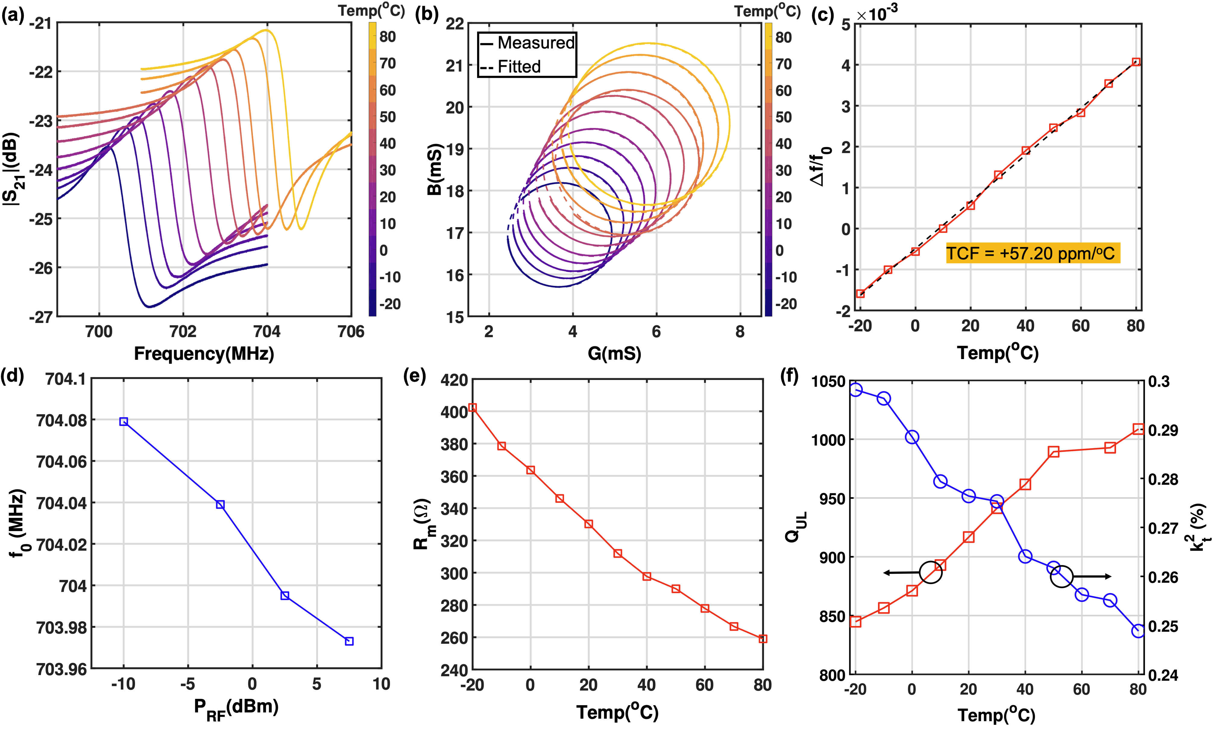
The mechanical Q exhibits an increase with temperature as shown in Fig.6(f). This behaviour is attributed to an increase in the mechanical Q of the ferroelectric PZT layer PZTQm1_Satoh1998TemperatureDO ; PZTQm2_Miclea2007EffectOT which bolsters . From the obtained temperature and high RF power characteristics of the resonator obtained through extraction, a more complete picture of the resonator characteristics can be developed. First, the shift in resonance frequency due to increasing is investigated. Possible origins of the shift include self heating caused by increasing RF amplitude or a change in stiffness. From Fig.6(d) we see that resonance frequency reduces as increases, which is the opposite trend to the temperature-dependent increase seen in Fig.6(c). We conclude that the negative shift in the resonance frequency occurs due to a reduction in stiffness associated with the mode of interest. The physical origin of the reduction in motional resistance with increasing can be traced to three mechanisms Wang2015PiezoelectricNI . To better understand these mechanisms, let us consider in terms of the equivalent motional parameters of the resonance mode:
| (2) |
where and are the effective stiffness and mass associated with the mode and and are the electromechanical coupling coefficients associated with the input and output transducers. Any reduction in is caused by a reduction in stiffness , increase in , and increase in electromechanical coupling coefficients and . We have established a stiffness reduction with increasing . In addition, the PZT piezoelectric coefficients and were experimentally determined to exhibit RF amplitude dependence, and follow the Rayleigh equation LSPZT4_Taylor1999NonlinearCT :
| (3) |
where represents the reversible domain wall contribution to the electromechanical response, is the Rayleigh constant and is the amplitude of the electric field. Since the electromechanical coupling coefficients and are directly proportional to the piezoelectric coefficients, we can expect them to increase with . Therefore, the reduction in can be attributed to and alongside the reduction in stiffness with . Improvement in with increasing temperature can also be explained in a similar manner where there is an increase in the .
5 Conclusion
This work represents the first study of large signal characteristics in ferroelectric CMOS-MEMS resonators monolithically embedded in a commercial BEOL process stack. The primary application scenarios involve but are not limited to carrier generation and adaptive RF front-end filtering. Large signal treatment of ferroelectric transducers originally intended for low voltage operation in FRAM/FeFET is applicable to all such devices currently under development for the aforementioned applications. The first nonlinear large signal model and extraction methodology has been developed to obtain the performance characteristics under a wide range of biasing and RF power conditions. The inherent nonlinear mechanisms present in the electromechanical transduction can be leveraged for applications such as in-sensor computation and autonomous adaptive radio front-ends. It has been shown that the FeCAP resonator undergoes a reduction in both the and with due to irreversible extrinsic electromechanical transduction unique to ferroelectrics. The performance of oscillators making use of these resonators is discussed in the context of phase noise and power dissipation, while considering the effect of nonlinearities. The influence of nonlinear behaviour on the design of switchable RF front end filters has also been illustrated through the use of IIP3 and -dependent characterization to set the optimal point for passband and bandstop type configurations. Finally, temperature dependence has been characterized tying together the understanding of performance variation under high . Analysis and design guidelines presented in this work for CMOS-MEMS ferroelectric resonators can facilitate additional functionality in standard RF CMOS and emerging 3D heterogeneously integrated (3DHI) ICs with minor or no modifications to manufacturing and packaging thereby enabling ultimate miniaturization.
6 Supplementary
6.1 Modeling Background and Challenges
To construct an appropriate strategy for the modeling of unreleased CMOS-MEMS ferroelectric resonators, the applicability of previously developed techniques for conventional SAW/BAW and ferroelectric devices must be evaluated. Three primary modeling approaches typically used for acoustic devices RFfilters1 include 1-D acoustic models such as Mason’s model, P-Matrix and the Coupling-of-Modes (COM)-model based on constitutive equations, behavioural models like the modified Butterworth-van-Dyke (mBVD) model and black-box Poly Harmonic Distortion (PHD) model. For the unreleased resonant ferroelectric device under consideration, we first discuss appropriate model selection based on challenges of bias-dependent small-signal modeling and extraction. Subsequently, we address issues pertaining to the expansion of the chosen small-signal modeling methodology to incorporate the large-signal behaviour.
Tunable FBAR devices BST_FBAR based on ferroelectric transducers such as BaxSr1-xTiO3(BST) in its paraelectric phase have previously been modeled using both the mBVD BST_FBAR_MBVD1 BST_FBAR_MBVD2 and 1-D acoustic transmission-line models BST_FBAR_Masons1 BST_FBAR_Masons2 . MBVD models have also been used in the context of released PZT resonators PZT_released_MBVD1 PZT_released_MBVD2 but no attempt has yet been made to match the model consisting of bias-dependent parameters to the measured response characteristics under different operating conditions. The mBVD model extraction of ferroelectric BST FBARs relies on low-frequency extraction of the transducer capacitance , which can be obtained from the imaginary part of input impedance as shown in Fig.7(a). The extracted capacitance is then fitted to the well-known closed-form expression developed for BST varactors BST_Varactor . Unlike the BST FBAR, the primary impediment to the direct extraction of transducer capacitances and in unreleased CMOS ferroelectric resonators is the presence of feedthrough paths between the input and output ports as shown in Fig.7. Due to this, the imaginary part of the input impedance at low frequencies does not yield the correct values of the transducer capacitances. An additional challenge is that, unlike in paraelectric-phase BST, capacitance of ferroelectric PbxZr1-xTiO3(PZT) exhibits a hysteretic nature which requires separate modeling treatment HysteresisModeling for compatibility with RF simulation tools. The remainder of the extraction procedure TuneableFBARs for the motional branch components (, and ) is based on the modeling of the series and parallel resonance frequencies and with changing bias and extraction of the motional, unloaded Q . In the case of low- and moderate feedthrough such as in this work, it is not possible to uniquely determine the series resonant frequency for certain bias conditions since the resonance peak height is smaller than 3 dB. A different modeling and extraction procedure is needed for unreleased CMOS-MEMS ferroelectric resonators. Previous attempts at modeling the small-signal behaviour of these devices he_switchable_2019 ; he_tunable_2020 have been restricted to a limited number of biasing conditions and do not capture the full experimentally observed behaviour.
Mason’s model implementations, such as those in BST_FBAR_Masons1 , are more amenable to FBAR-like devices consisting of different materials in the device stack. Similarly, other comprehensive models such as that in BST_FBAR_Masons2 make use of elastic and electrostrictive equivalent model slices based on full-field formulations and incorporation of nonlinear electrostrictive coupling terms. However, this approach is not applicable in the case of unreleased BEOL ferroelectric CMOS-MEMS devices due to more complicated geometries and mode shapes with a multitude of materials. As such, an augmented mBVD behavioural model as depicted in Fig.2(a) has been chosen to accurately capture the bias-dependent small-signal performance of the devices under consideration. Additionally, augmentation of the mBVD model to adequately incorporate large-signal nonlinearities has been studied previously in the context of FBAR devices further cementing the suitability of this approach for the same operation scenarios.
6.2 Extraction Methodology
As mentioned previously, the mBVD model in he_switchable_2019 cannot be used to capture performance variation with change in operating conditions due to absence of effects such as loss mechanisms in the ferroelectric material and capacitive coupling between the adjacent IDTs. These shortcomings result in a mismatch of greater than 2 dB between the measured and modeled transmission for different biases as well as RF power levels. The augmented mBVD model in Fig.2(a) significantly improves the discrepancy in the model’s transmission response with respect to the measured de-embedded device data to within 1 dB for a majority of operating conditions through the incorporation of FeCAP transducer loss elements and in series with the corresponding intrinsic transducer capacitances and . These loss elements, just like the capacitances themselves, are and dependent. The series combination of and captures the inter-finger capacitance and associated dielectric loss of the BEOL dielectric and is invariant with and applied to the device. The resistances and are used to model the routing resistance from the de-embedding plane to the device under test. The motional branch components of the model including motional resistance , motional inductance , and motional capacitance are interrelated through mechanical resonance frequency (angular frequency ) and mechanical Q as follows (the bias and RF power dependence of each of these quantities has been omitted for simplicity):
| (4) |
| (5) |
The magnitude of piezoelectric coupling coefficients and , corresponding to the ferroelectric transducers, are implicitly included in the motional components as follows:
| (6) |
| (7) |
| (8) |
where , and are the motional branch circuit parameters independent of electromechanical coupling. This explicit separation of motional and electromechanical transducer parameters is done to allow direct extraction of from measurements across bias and RF powers and insertion directly into the model as initial values prior to optimization.
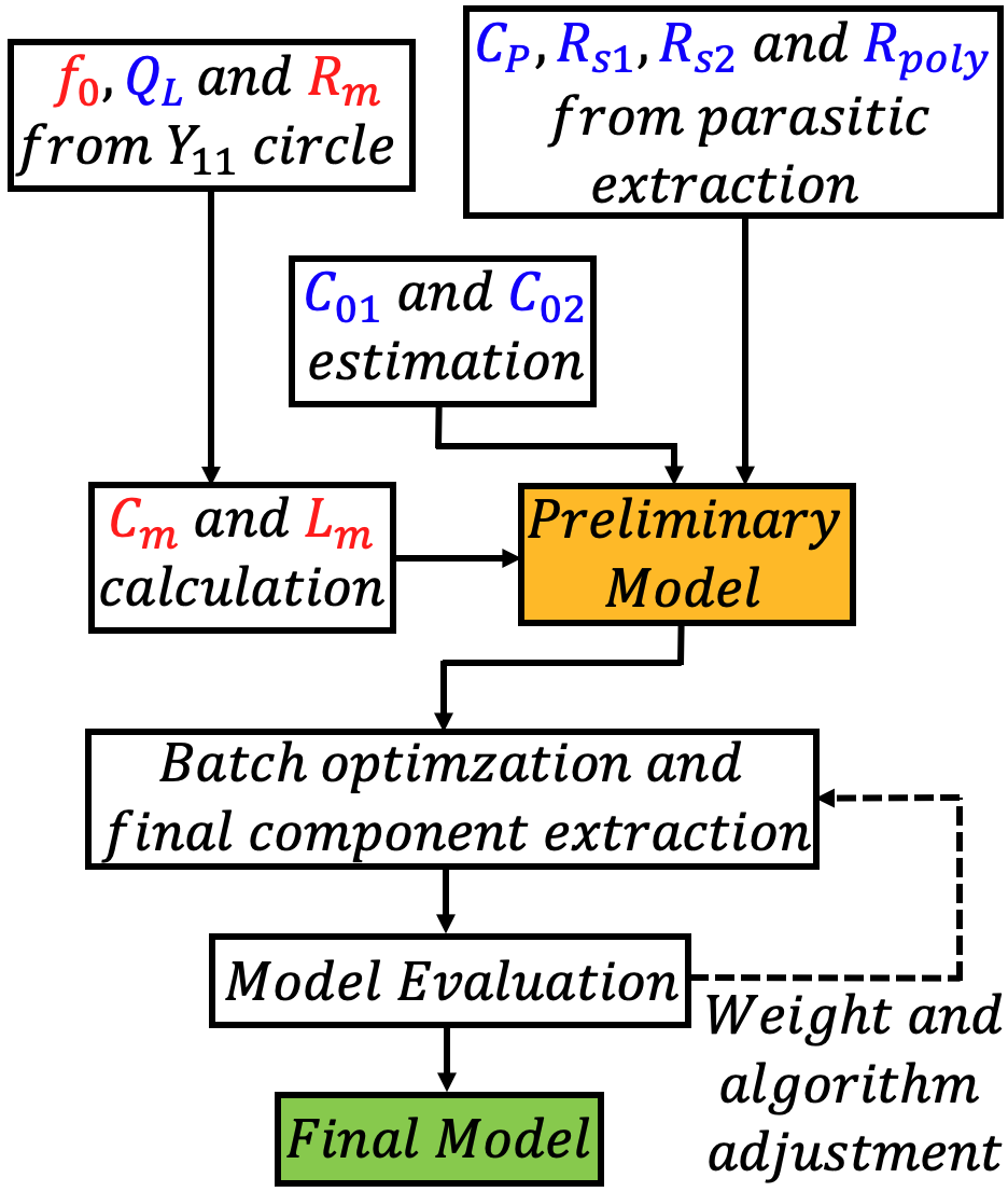
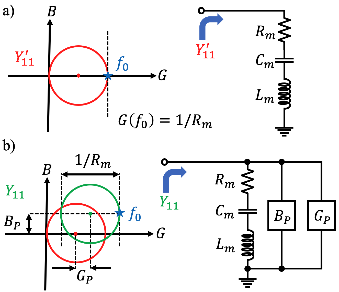
Once the model structure has been finalized and all the necessary circuit components with a physical basis have been included, a parameter/component extraction is required to build a preliminary model for the resonator. The first step in this procedure (as seen in Fig.8) is the estimation of the motional branch parameters from the measured data across biases after open and short de-embedding. To overcome the modeling challenges mentioned in the previous section, an admittance circle based methodology is adopted JEYLee_feedthrough . If only the motional branch of the model is considered then the admittance looking into the branch is given by:
| (9) |
where and are the conductance and susceptance respectively which are given by:
| (10a) | |||
| (10b) |
from these equations the admittance circular locus equation can be obtained as follows:
| (11) |
This admittance circle has been depicted in the Nyquist plot schematic of Fig.9(a). The frequency corresponds to the mechanical resonance frequency of the mode under consideration (). The inverse of the circle’s diameter is equivalent to . Parallel feedthrough branches corresponding to IDT coupling capacitance and the intrinsic ferroelectric capacitances , as well as together contribute an equivalent conductance and susceptance as can be seen in Fig9(b). Since the resonance is high-Q and the feedthrough level is moderate, it can be assumed that and are invariant with frequency in the frequency range under consideration. Under this assumption, the circle is shifted in the Nyquist plane by and along the and axes, respectively. It should be noted that the diameter of the admittance circle () does not change when additional components are added in parallel to the motional branch which is instrumental in the direct extraction of from measurement.
Furthermore, the point corresponding to the maximum conductance is used to obtain the mechanical resonance frequency . The maxima and minima points of the susceptance correspond to the two -3dB frequencies. Using the obtained and the two -3dB frequencies, the loaded Q can be obtained from the 3dB bandwidth: . Under conditions of moderate feedthrough the -3dB frequencies deviate slightly from the series and parallel resonance frequencies ( and )JEYLee_feedthrough . Using the relations highlighted in equations 4 and 5 the corresponding initial estimates of and can be obtained. The series routing resistances and also influence these calculations but the obtained values still serve as a good starting point for the optimization engines subsequently used.
Using layout extraction (as in Rawat11GHz ), parasitic electrical components including , , and can be estimated and fed back into the preliminary model. The de-embedding plane used for obtaining the device measurement characteristics using on-chip open and short structures is considered while estimating these parasitic elements. Although the transducer capacitances extracted from the ferroelectric P-E loop measurement in he_switchable_2019 do not capture the accurate values because of challenges enumerated in Section 6.1, they are still used in the pre-optimization model to get a good initial estimate. Once the preliminary model has been prepared, a batch optimization is carried out using Keysight® ADS across different bias voltages () and RF powers . The error function is appropriately set to minimize deviation in the model magnitude as well as phase response with respect to the measured de-embedded device characteristics. The model fit quality is subsequently evaluated and requisite adjustments in the optimization weights and algorithms are made to obtain the final model which fits as close as possible to the measured data at the bias points considered.
6.3 Model Benchmarking
 |
 |
 |
 |
The comparison of the measured transmission magnitude and phase characteristics with respect to the model is shown in Fig.10(a) and (b) across different values traversing along the P-E loop. It can be observed that model matches closely with the measured characteristics. This demonstrates the efficacy of the small-signal model extraction methodology that has been described in the previous section. The extraction methodology remains unchanged for large signal operation since the relations governing the model operation remain constant with varying amplitude. This can be qualitatively understood in terms of a basic Volterra series formulation bookVolterra for the large-signal transadmittance response of the equivalent circuit model of Fig.2(a). Assuming that an input voltage of amplitude and frequency given by is applied to port 1 (P1) of the model, then the output current at port 2 (P2) may be represented in the form:
| (12) |
where the transfer functions represent the Fourier Transform of the corresponding -th order Volterra kernels corresponding to the transadmittance . With an increasing input amplitude , the overall magnitude and phase response of the device deviates from the linear response due to under small-signal conditions due to the action of higher order kernels , and so on. Each remaining individual Volterra kernel in itself is dependent upon the nonlinear coefficients of the various components in the model as well as other kernels. The primary goal is to determine these nonlinear coefficients of the individual components using the extracted component values at different RF power levels to construct a nonlinear large-signal model of the resonator.
To make the nonlinear resonator model amenable to circuit simulation, it is desirable to make the nonlinear model components voltage- and current-dependent rather than dependent. The technique highlighted in LSSP_BSTFBAR , applied to a standard 1-port FBAR model, is augmented and utilized to capture the nonlinear behaviour of the motional as well as transducer components. The behavior of each of these components is captured using a power series as follows:
| (13a) | |||
| (13b) | |||
| (13c) |
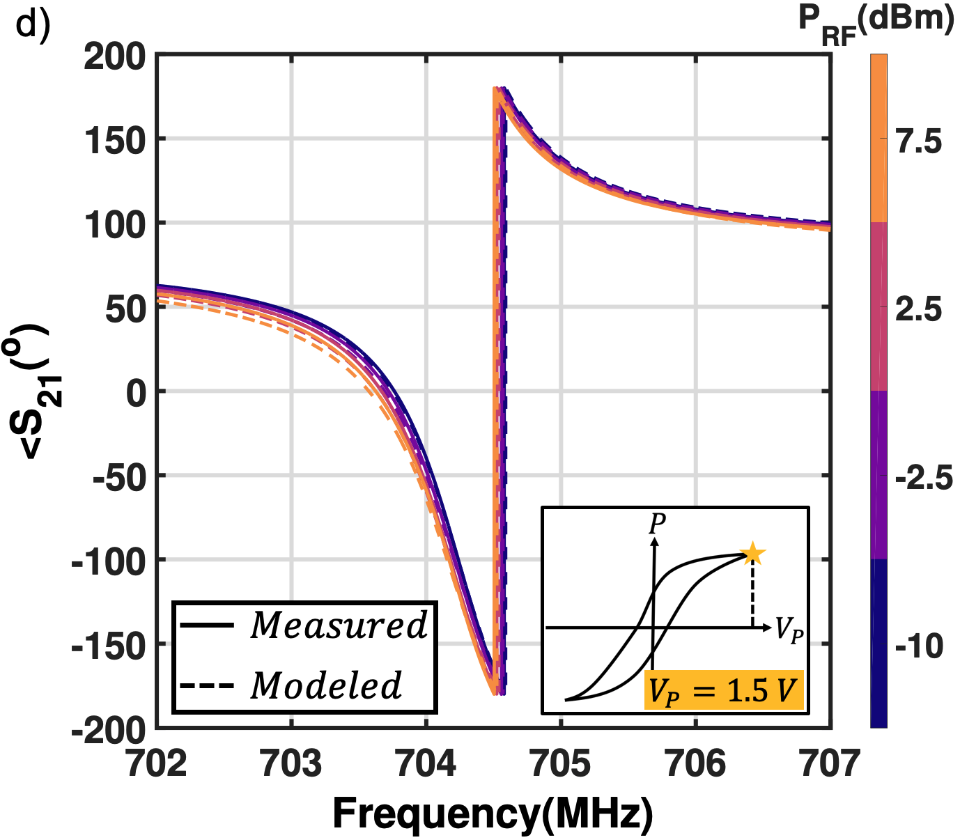
where , and ( to ) are polarization-dependent nonlinear coefficients, is the current through the motional branch and is the voltage across the motional capacitor. The frequency-dependent and are used to calculate the nonlinear coefficients for all the polarization voltages under consideration. The components are then implemented using equations based Symbolically Defined Device (SDD) components in Keysight® ADS. Subsequently, harmonic balance (HB) large-signal S-parameter simulation is carried out to compare the model output against the measured device response. From Fig.10(c) and (d), it can be seen that for of 1.5V, the model matches closely with measured device S-parameters across multiple values. Optimization of fitting to the power series across different s ensures that the model S-parameter magnitude is within 1 dB of the measured response magnitude. Similarly, it is ensured that the model phase does not deviate beyond from the measured phase characteristics.
References
- \bibcommenthead
- (1) Aigner, R., Fattinger, G.: 3g – 4g – 5g: How baw filter technology enables a connected world. 2019 20th International Conference on Solid-State Sensors, Actuators and Microsystems & Eurosensors XXXIII (TRANSDUCERS & EUROSENSORS XXXIII), 523–526 (2019)
- (2) Fattinger, G., Volatier, A., Al-Joumayly, M., Yusuf, Y.A., Aigner, R., Khlat, N., Granger-Jones, M.: Carrier aggregation and its challenges - or: The golden age for acoustic filters. 2016 IEEE MTT-S International Microwave Symposium (IMS), 1–4 (2016)
- (3) Hagelauer, A., Fattinger, G., Ruppel, C.C.W., Ueda, M., Hashimoto, K.-y., Tag, A.: Microwave acoustic wave devices: Recent advances on architectures, modeling, materials, and packaging. IEEE Transactions on Microwave Theory and Techniques 66(10), 4548–4562 (2018). https://doi.org/10.1109/TMTT.2018.2854160
- (4) Ruby, R.: A snapshot in time: The future in filters for cell phones. IEEE Microwave Magazine 16(7), 46–59 (2015). https://doi.org/10.1109/MMM.2015.2429513
- (5) Aigner, R.: Saw and baw technologies for rf filter applications: A review of the relative strengths and weaknesses. In: 2008 IEEE Ultrasonics Symposium, pp. 582–589 (2008). https://doi.org/10.1109/ULTSYM.2008.0140
- (6) Ruppel, C.C.W.: Acoustic wave filter technology–a review. IEEE Transactions on Ultrasonics, Ferroelectrics, and Frequency Control 64(9), 1390–1400 (2017). https://doi.org/10.1109/TUFFC.2017.2690905
- (7) Koohi, M.Z., Mortazawi, A.: Reconfigurable radios employing ferroelectrics: Recent progress on reconfigurable rf acoustic devices based on thin-film ferroelectric barium strontium titanate. IEEE Microwave Magazine 21, 120–135 (2020)
- (8) Lee, S., Mortazawi, A.: An intrinsically switchable ladder-type ferroelectric bst-on-si composite fbar filter. IEEE Transactions on Ultrasonics, Ferroelectrics, and Frequency Control 63(3), 456–462 (2016). https://doi.org/10.1109/TUFFC.2016.2517643
- (9) Ni, K., Dutta, S., Datta, S.: Ferroelectrics: From memory to computing. 2020 25th Asia and South Pacific Design Automation Conference (ASP-DAC), 401–406 (2020)
- (10) Liu, X., Ting, J.-A., He, Y., Fiagbenu, M.M.A., Zheng, J.X., Wang, D., Frost, J., Musavigharavi, P., Esteves, G., Kisslinger, K., Anantharaman, S.B., Stach, E.A., Olsson, R.H., Jariwala, D.: Reconfigurable compute-in-memory on field-programmable ferroelectric diodes. Nano letters (2022)
- (11) Dutta, S., Ye, H., Chakraborty, W., Luo, Y.-C., Jose, M.S., Grisafe, B., Khanna, A., Lightcap, I., Shinde, S.R., Yu, S., Datta, S.: Monolithic 3d integration of high endurance multi-bit ferroelectric fet for accelerating compute-in-memory. 2020 IEEE International Electron Devices Meeting (IEDM), 36–413644 (2020)
- (12) Han, G., Peng, Y., Liu, H., Zhou, J., Luo, Z., Chen, B., Cheng, R., Jin, C., Xiao, W., Liu, F., Zhao, J., Wang, S., Yu, X., Liu, Y., Hao, Y.: Ferroelectric devices for intelligent computing. Intelligent Computing (2022)
- (13) Peng, Y., Xu, N., Liu, T.-J.K., Hao, Y., Xiao, W., Han, G., Liu, Y., Wu, J., Wang, K., He, Y., Yu, Z., Wang, X.: Nanocrystal-embedded-insulator (nei) ferroelectric field-effect transistor featuring low operating voltages and improved synaptic behavior. IEEE Electron Device Letters 40, 1933–1936 (2019)
- (14) Kim, M.-K., Kim, I.-J., Lee, J.-S.: Cmos-compatible compute-in-memory accelerators based on integrated ferroelectric synaptic arrays for convolution neural networks. Science Advances 8 (2022)
- (15) Wan, T., Shao, B., Ma, S., Zhou, Y.-H., Li, Q., Chai, Y.: In-sensor computing: Materials, devices, and integration technologies. Advanced materials, 2203830 (2022)
- (16) Datta, G., Liu, Z., Kaiser, M.A.-A., Kundu, S., Mathai, J., Yin, Z., Jacob, A.P., Jaiswal, A.R., Beerel, P.A.: In-sensor & neuromorphic computing are all you need for energy efficient computer vision. ArXiv abs/2212.10881 (2022)
- (17) Zhu, Y., Zhu, Y., Mao, H., He, Y., Jiang, S., Zhu, L.Q., Chen, C., Wan, C.J., Wan, Q.: Recent advances in emerging neuromorphic computing and perception devices. Journal of Physics D: Applied Physics 55 (2021)
- (18) Hoople, J., Kuo, J., Abdel-moneum, M., Lal, A.: Chipscale ghz ultrasonic channels for fingerprint scanning. In: 2015 IEEE International Ultrasonics Symposium (IUS), pp. 1–4 (2015). https://doi.org/10.1109/ULTSYM.2015.0027
- (19) Fei, C., Chiu, C.T., Chen, X., Chen, Z., Ma, J., Zhu, B., Shung, K.K., Zhou, Q.: Ultrahigh frequency (100 mhz-300 mhz) ultrasonic transducers for optical resolution medical imaging. Scientific Reports 6 (2016)
- (20) Matsuda, O., Larciprete, M., Voti, R.L., Wright, O.B.: Fundamentals of picosecond laser ultrasonics. Ultrasonics 56, 3–20 (2015)
- (21) Balasubramanian, P., Singh, A.K., Xu, C., Lal, A.: Ghz ultrasonic chip-scale device induces ion channel stimulation in human neural cells. Scientific Reports 10 (2020)
- (22) Tharpe, T., Dabas, S., Mo, D., Tabrizian, R.: A 17.3 GHZ ATOMIC-LAYERED HZO SOLIDLY MOUNTED RESONATOR: TOWARDS CMOS-BEOL MM-WAVE FREQUENCY CONTROL. In: 2022 Solid-State, Actuators, and Microsystems Workshop Technical Digest. Transducer Research Foundation, Hilton Head, South Carolina, USA (2022)
- (23) Ghatge, M., Walters, G., Nishida, T., Tabrizian, R.: An ultrathin integrated nanoelectromechanical transducer based on hafnium zirconium oxide. Nature Electronics, 1–7 (2019)
- (24) Ghatge, M., Walters, G., Nishida, T., Tabrizian, R.: A Nano-Mechanical Resonator with 10nm Hafnium-Zirconium Oxide Ferroelectric Transducer. In: 2018 IEEE International Electron Devices Meeting (IEDM), pp. 4–61464 (2018). https://doi.org/10.1109/IEDM.2018.8614633
- (25) Ghatge, M., Walters, G., Nishida, T., Tabrizian, R.: A Non-Reciprocal Filter Using Asymmetrically Transduced Micro-Acoustic Resonators. IEEE Electron Device Letters 40(5), 800–803 (2019). https://doi.org/10.1109/LED.2019.2907089. Conference Name: IEEE Electron Device Letters
- (26) Ghatge, M., Walters, G., Nishida, T., Tabrizian, R.: A 30-nm thick integrated hafnium zirconium oxide nano-electro-mechanical membrane resonator. Applied Physics Letters 116(4), 043501 (2020). https://doi.org/10.1063/1.5134856. Publisher: American Institute of Physics. Accessed 2021-10-07
- (27) Tharpe, T., Hakim, F., Tabrizian, R.: In-Plane Bulk Acoustic Resonators Using 50nm-Thick Nano-Laminated Ferroelectric Hf0. 5Zr0. 5O2. In: 2021 21st International Conference on Solid-State Sensors, Actuators and Microsystems (Transducers), pp. 313–316. IEEE, ??? (2021)
- (28) Hakim, F., Tharpe, T., Tabrizian, R.: Ferroelectric-on-Si Super-High-Frequency Fin Bulk Acoustic Resonators With Hf0.5Zr0.5O2 Nanolaminated Transducers. IEEE Microwave and Wireless Components Letters 31(6), 701–704 (2021). https://doi.org/10.1109/LMWC.2021.3067509. Conference Name: IEEE Microwave and Wireless Components Letters
- (29) Rassay, S., Mo, D., Li, C., Choudhary, N., Forgey, C., Tabrizian, R.: Intrinsically switchable ferroelectric scandium aluminum nitride lamb-mode resonators. IEEE Electron Device Letters 42(7), 1065–1068 (2021). https://doi.org/10.1109/LED.2021.3078444
- (30) Wang, J., Park, M., Mertin, S., Pensala, T., Ayazi, F., Ansari, A.: A film bulk acoustic resonator based on ferroelectric aluminum scandium nitride films. Journal of Microelectromechanical Systems 29, 741–747 (2020)
- (31) Wang, J., Park, M., Ansari, A.: High-Temperature Acoustic and Electric Characterization of Ferroelectric Al $_0.7$ Sc $_0.3$ N Films. Journal of Microelectromechanical Systems, 1–7 (2022). https://doi.org/10.1109/JMEMS.2022.3147492. Conference Name: Journal of Microelectromechanical Systems
- (32) Boescke, T.S., Muller, J., Brauhaus, D., Schroder, U., Bottger, U.: Ferroelectricity in Hafnium Oxide Thin Films. Applied Physics Letters 99(10), 102903 (2011). https://doi.org/10.1063/1.3634052
- (33) Polakowski, P., Mueller, J.: Ferroelectricity in undoped hafnium oxide. Applied Physics Letters 106(23), 232905 (2015). https://doi.org/10.1063/1.4922272
- (34) Müller, J., Polakowski, P., Mueller, S., Mikolajick, T.: Ferroelectric hafnium oxide based materials and devices: Assessment of current status and future prospects. ECS Journal of Solid State Science and Technology 4 (2015)
- (35) Park, M.H., Kwon, D.-C., Schroeder, U., Mikolajick, T.: Binary ferroelectric oxides for future computing paradigms. MRS Bulletin (2021)
- (36) Schroeder, U., Park, M.H., Mikolajick, T., Hwang, C.S.: The fundamentals and applications of ferroelectric hfo2. Nature Reviews Materials 7, 653–669 (2022)
- (37) Fichtner, S., Lofink, F., Wagner, B., Schönweger, G., Kreutzer, T.-N., Petraru, A., Kohlstedt, H.: Ferroelectricity in AlScN: Switching, Imprint and sub-150 nm Films. In: 2020 Joint Conference of the IEEE International Frequency Control Symposium and International Symposium on Applications of Ferroelectrics (IFCS-ISAF), pp. 1–4 (2020). https://doi.org/10.1109/IFCS-ISAF41089.2020.9234883. ISSN: 2375-0448
- (38) Fichtner, S., Wolff, N., Lofink, F., Kienle, L., Wagner, B.: AlScN: A III-V semiconductor based ferroelectric. Journal of Applied Physics 125(11), 114103 (2019). https://doi.org/10.1063/1.5084945. Publisher: American Institute of Physics. Accessed 2022-02-13
- (39) Marathe, R., Wang, W., Weinstein, D.: Si-based unreleased hybrid mems-cmos resonators in 32nm technology. In: 2012 IEEE 25th International Conference on Micro Electro Mechanical Systems (MEMS), pp. 729–732 (2012). https://doi.org/10.1109/MEMSYS.2012.6170289
- (40) Bahr, B.: Monolithically Integrated MEMS Resonators and Oscillators in Standard IC Technology. PhD Thesis, Massachusetts Institute of Technology, Boston (June 2016)
- (41) Bahr, B., He, Y., Krivokapic, Z., Banna, S., Weinstein, D.: 32GHz resonant-fin transistors in 14nm FinFET technology. In: 2018 IEEE International Solid - State Circuits Conference - (ISSCC), pp. 348–350 (2018). https://doi.org/10.1109/ISSCC.2018.8310327
- (42) Bahr, B., Marathe, R., Weinstein, D.: Theory and Design of Phononic Crystals for Unreleased CMOS-MEMS Resonant Body Transistors. Journal of Microelectromechanical Systems 24(5), 1520–1533 (2015). https://doi.org/10.1109/JMEMS.2015.2418789
- (43) He, Y., Bahr, B., Si, M., Ye, P., Weinstein, D.: A tunable ferroelectric based unreleased RF resonator. Microsystems & Nanoengineering 6(1), 1–7 (2020). https://doi.org/10.1038/s41378-019-0110-1. Number: 1 Publisher: Nature Publishing Group. Accessed 2021-05-24
- (44) He, Y., Bahr, B., Weinstein, D.: A FERROELECTRIC CAPACITOR (FECAP) BASED UNRELEASED RESONATOR. In: 2018 Solid-State, Actuators, and Microsystems Workshop Technical Digest, pp. 71–74. Transducer Research Foundation, Hilton Head, South Carolina, USA (2018). https://doi.org/10.31438/trf.hh2018.19
- (45) He, Y., Bahr, B., Si, M., Ye, P., Weinstein, D.: Switchable Mechanical Resonance Induced by Hysteretic Piezoelectricity in Ferroelectric Capacitors. In: 2019 20th International Conference on Solid-State Sensors, Actuators and Microsystems Eurosensors XXXIII (TRANSDUCERS EUROSENSORS XXXIII), pp. 717–720 (2019). https://doi.org/10.1109/TRANSDUCERS.2019.8808623. ISSN: 2167-0021
- (46) McAdams, H.P., Acklin, R., Blake, T.G.W., Du, X.-H., Eliason, J., Fong, J.Y., Kraus, W., Liu, D., Madan, S.K., Moise, T.S., Natarajan, S., Ning, Q., Qiu, Y., Remack, K., Rodriguez, J.A., Roscher, J., Seshadri, A., Summerfelt, S.R.: A 64-mb embedded fram utilizing a 130-nm 5lm cu/fsg logic process. IEEE Journal of Solid-State Circuits 39, 667–677 (2004)
- (47) Udayakumar, K.R., Boku, K., Remack, K., Rodriguez, J.A., Aggarwal, S., Celii, F.G., Martin, J.S., Matz, L., Summerfelt, S.R., Moise, T.S.: Integration and bit distribution of production-worthy fram embedded with 130nm cmos logic. Symposium Non-Volatile Memory Technology 2005., 2–44 (2005)
- (48) Mikolajick, T., Schroeder, U., Slesazeck, S.: The past, the present, and the future of ferroelectric memories. IEEE Transactions on Electron Devices 67, 1434–1443 (2020)
- (49) Francois, T., Grenouillet, L., Coignus, J., Blaise, P., Carabasse, C., Vaxelaire, N., Magis, T., Aussenac, F., Loup, V., Pellissier, C., Slesazeck, S., Havel, V., Richter, C., Makosiej, A., Giraud, B., Breyer, E.T., Materano, M., Chiquet, P., Bocquet, M., Nowak, E., Schroeder, U., Gaillard, F.: Demonstration of beol-compatible ferroelectric hf0.5zr0.5o2 scaled feram co-integrated with 130nm cmos for embedded nvm applications. In: 2019 IEEE International Electron Devices Meeting (IEDM), pp. 15–711574 (2019). https://doi.org/10.1109/IEDM19573.2019.8993485
- (50) Khan, A.I., Keshavarzi, A., Datta, S.: The future of ferroelectric field-effect transistor technology. (2020)
- (51) Dünkel, S., Trentzsch, M., Richter, R., Moll, P., Fuchs, C., Gehring, O., Majer, M., Wittek, S., Müller, B., Melde, T., Mulaosmanovic, H., Slesazeck, S., Müller, S., Ocker, J., Noack, M., Löhr, D.-A., Polakowski, P., Müller, J., Mikolajick, T., Höntschel, J., Rice, B., Pellerin, J., Beyer, S.: A fefet based super-low-power ultra-fast embedded nvm technology for 22nm fdsoi and beyond. In: 2017 IEEE International Electron Devices Meeting (IEDM), pp. 19–711974 (2017). https://doi.org/10.1109/IEDM.2017.8268425
- (52) Müller, J., Yurchuk, E., Schlösser, T., Paul, J., Hoffmann, R., Müller, S., Martin, D., Slesazeck, S., Polakowski, P., Sundqvist, J., Czernohorsky, M., Seidel, K., Kücher, P., Boschke, R., Trentzsch, M., Gebauer, K., Schröder, U., Mikolajick, T.: Ferroelectricity in hfo2 enables nonvolatile data storage in 28 nm hkmg. In: 2012 Symposium on VLSI Technology (VLSIT), pp. 25–26 (2012). https://doi.org/10.1109/VLSIT.2012.6242443
- (53) Celii, F.G., Thakre, M., Gay, M.K., Summerfelt, S.R., Aggarwal, S., Martin, J.S., Hall, L., Udayakumar, K.R., Moise, T.S.: Plasma etch processes for embedded fram integration. Integrated Ferroelectrics 53(1), 269–277 (2003). https://doi.org/10.1080/10584580390258183
- (54) Park, M., Ansari, A.: Formation, evolution, and tuning of frequency combs in microelectromechanical resonators. Journal of Microelectromechanical Systems 28(3), 429–431 (2019). https://doi.org/10.1109/JMEMS.2019.2898003
- (55) Larson, J.D., Bradley, P.D., Wartenberg, S.A., Ruby, R.C.: Modified butterworth-van dyke circuit for fbar resonators and automated measurement system. 2000 IEEE Ultrasonics Symposium. Proceedings. An International Symposium (Cat. No.00CH37121) 1, 863–8681 (2000)
- (56) Bjurstrom, J., Vestling, L., Olsson, J., Katardjiev, I.: An accurate direct extraction technique for the mbvd resonator model. 34th European Microwave Conference, 2004. 3, 1241–1244 (2004)
- (57) Campanella, H., Nouet, P., de Paco, P., Uranga, A., Barniol, N., Esteve, J.: Automated on-wafer characterization in micro-machined resonators: towards an integrated test vehicle for bulk acoustic wave resonators (fbar). 2007 IEEE International Conference on Microelectronic Test Structures, 157–161 (2007)
- (58) Campanella, H., Uranga, A., Nouet, P., Sanchez, P.D.P., Barniol, N., Esteve, J.: Instantaneous de-embedding of the on-wafer equivalent-circuit parameters of acoustic resonator (fbar) for integrated circuit applications. Proceedings of the 20th annual conference on Integrated circuits and systems design (2007)
- (59) Erbes, A., Prasad, A., Seshia, A.A.: High-frequency piezoelectric-on-si mems resonator and numerical method for parameter extraction. 2014 European Frequency and Time Forum (EFTF), 305–307 (2014)
- (60) Damjanovic, D., Taylor, D.V.: Contributions to the nonlinear dielectric and piezoelectric response of ferroelectric thin films and ceramics. Ferroelectrics 221, 137–146 (1999)
- (61) Taylor, D.V., Damjanovic, D.: Domain wall pinning contribution to the nonlinear dielectric permittivity in pb(zr, ti)o3 thin films. Applied Physics Letters 73, 2045–2047 (1998)
- (62) Taylor, D.V., Damjanovic, D., Setter, N.: Nonlinear contributions to dielectric and piezoelectric properties in lead zirconate titanate thin films. Ferroelectrics 224, 727–734 (1999)
- (63) Gerber, P., Kügeler, C., Böttger, U., Waser, R.: Effects of ferroelectric switching on the piezoelectric small-signal response (d33) and electrostriction (m33) of lead zirconate titanate thin films. Journal of Applied Physics 95, 4976–4980 (2004)
- (64) Zhang, Q., Pan, W.Y., Jang, S.J., Cross, L.E.: Domain wall excitations and their contributions to the weak‐signal response of doped lead zirconate titanate ceramics. Journal of Applied Physics 64, 6445–6451 (1988)
- (65) Hall, D.A., Ben-Omran, M.M., Stevenson, P.J.: Field and temperature dependence of dielectric properties in -based piezoceramics. Journal of Physics: Condensed Matter 10, 461–476 (1998)
- (66) Bedair, S.S., Judy, D., Pulskamp, J.S., Polcawich, R., Gillon, A., Hwang, E., Bhave, S.A.: High rejection, tunable parallel resonance in micromachined lead zirconate titanate on silicon resonators. Applied Physics Letters 99, 103509 (2011)
- (67) Li, S., Cao, W., Cross, L.E.: The extrinsic nature of nonlinear behavior observed in lead zirconate titanate ferroelectric ceramic. Journal of Applied Physics 69, 7219–7224 (1991)
- (68) Bolten, D., Lohse, O., Grossmann, M., Waser, R.: Reversible and irreversible domain wall contributions to the polarization in ferroelectric thin films. Ferroelectrics 221, 251–257 (1999)
- (69) Bolten, D., Böttger, U., Waser, R.: Reversible and irreversible polarization processes in ferroelectric ceramics and thin films. (2002)
- (70) Lavasani, H.M., Abdolvand, R., Ayazi, F.: A 500mhz low phase-noise a1n-on-silicon reference oscillator. 2007 IEEE Custom Integrated Circuits Conference, 599–602 (2007)
- (71) Lin, Y.-W., Lee, S., Ren, Z., Nguyen, C.T.C.: Series-resonant micromechanical resonator oscillator. In: IEEE International Electron Devices Meeting 2003, pp. 39–413944 (2003). https://doi.org/10.1109/IEDM.2003.1269438
- (72) Reines, I., Park, S.-J., Rebeiz, G.M.: Compact low-loss tunable -band bandstop filter with miniature rf-mems switches. IEEE Transactions on Microwave Theory and Techniques 58(7), 1887–1895 (2010). https://doi.org/10.1109/TMTT.2010.2050621
- (73) Cheng, C.-C., Rebeiz, G.M.: A three-pole 1.2–2.6-ghz rf mems tunable notch filter with 40-db rejection and bandwidth control. IEEE Transactions on Microwave Theory and Techniques 60(8), 2431–2438 (2012). https://doi.org/10.1109/TMTT.2012.2198231
- (74) Wu, Z., Shim, Y., Rais-Zadeh, M.: Miniaturized uwb filters integrated with tunable notch filters using a silicon-based integrated passive device technology. IEEE Transactions on Microwave Theory and Techniques 60(3), 518–527 (2012). https://doi.org/10.1109/TMTT.2011.2178428
- (75) Koohi, M.Z., Mortazawi, A.: On the linearity of bst thin film bulk acoustic resonators. In: 2018 IEEE MTT-S International Microwave Workshop Series on Advanced Materials and Processes for RF and THz Applications (IMWS-AMP), pp. 1–3 (2018). https://doi.org/10.1109/IMWS-AMP.2018.8457167
- (76) Chai, Y.: In-sensor computing for machine vision. Nature 579, 32–33 (2020)
- (77) Cui, B., Fan, Z., Li, W., Chen, Y., Dong, S., Tan, Z., Cheng, S., Tian, B., Tao, R., Tian, G., Chen, D., Hou, Z., Qin, M., Zeng, M., Lu, X., Zhou, G., Gao, X., Liu, J.-m.: Ferroelectric photosensor network: an advanced hardware solution to real-time machine vision. Nature Communications 13 (2021)
- (78) Jadhav, S.S., Gund, V., Lal, A.: Programmable ferroelectric hzo nems mechanical multiplier for in-memory computing. 2023 IEEE 36th International Conference on Micro Electro Mechanical Systems (MEMS), 519–521 (2023)
- (79) Park, M., Ansari, A.: Phononic frequency combs in stand-alone piezoelectric resonators. 2018 IEEE International Frequency Control Symposium (IFCS), 1–4 (2018)
- (80) Park, M., Ansari, A.: Formation, evolution, and tuning of frequency combs in microelectromechanical resonators. Journal of Microelectromechanical Systems 28, 429–431 (2019)
- (81) Sharma, M., Sarraf, E.H., Baskaran, R., Cretu, E.: Parametric resonance: Amplification and damping in mems gyroscopes. Sensors and Actuators A-physical 177, 79–86 (2012)
- (82) Hu, Z., Gallacher, B.J., Burdess, J.S., Fell, C.P., Townsend, K.: A parametrically amplified mems rate gyroscope. Sensors and Actuators A-physical 167, 249–260 (2011)
- (83) Zhang, X.L., Chen, Z., Cross, L.E., Schulze, W.A.: Dielectric and piezoelectric properties of modified lead titanate zirconate ceramics from 4.2 to 300 k. Journal of Materials Science 18, 968–972 (1983)
- (84) Gerson, R.: Piezoelectric and dielectric properties of lead titanate zirconate ceramics at low temperatures. Journal of Applied Physics 33, 830–832 (1962)
- (85) Thiercelin, M., Dammak, H., Thi, M.P.: Electromechanical properties of pmn-pt and pzt ceramics at cryogenic temperatures. 2010 IEEE International Symposium on the Applications of Ferroelectrics (ISAF), 1–4 (2010)
- (86) Satoh, K., Ise, O., Tamura, M., Otsuki, E.: Temperature dependence of the mechanical quality factor of piezoelectric ceramics in pzt systems. Ieej Transactions on Fundamentals and Materials 118, 712–717 (1998)
- (87) Miclea, C., Tănăsoiu, C., Amarande, L., Miclea, C.F., Plăviţu, C.N., Cioangher, M., Trupina, L., Miclea, C.T., David, C.: Effect of temperature on the main piezoelectric parameters of a soft pzt ceramic. (2007)
- (88) Wang, S.P., Popa, L.C., Weinstein, D.: Piezoelectric nonlinearity in gan lamb mode resonators. 2015 Transducers - 2015 18th International Conference on Solid-State Sensors, Actuators and Microsystems (TRANSDUCERS), 989–992 (2015)
- (89) Norling, M., Berge, J., Gevorgian, S.: Parameter extraction for tunable tfbars based on bst. In: 2009 IEEE MTT-S International Microwave Symposium Digest, pp. 101–104 (2009). https://doi.org/10.1109/MWSYM.2009.5165642
- (90) Lee, S., Lee, V., Sis, S.A., Mortazawi, A.: A simple nonlinear mbvd model parameter extraction method for intrinsically switchable ferroelectric fbars. In: 2013 European Microwave Conference, pp. 1355–1358 (2013). https://doi.org/10.23919/EuMC.2013.6686917
- (91) Vendik, I.B., Turalchuk, P.A., Vendik, O.G., Berge, J.: Modeling tunable bulk acoustic resonators based on induced piezoelectric effect in batio3 and ba0.25sr0.75tio3 films. Journal of Applied Physics 103(1), 014107 (2008) https://doi.org/10.1063/1.2830866. https://doi.org/10.1063/1.2830866
- (92) Peng, W., Koohi, M.Z., Nam, S., Mortazawi, A.: Phenomenological circuit modeling of ferroelectric-driven bulk acoustic wave resonators. IEEE Transactions on Microwave Theory and Techniques 70(1), 919–925 (2022). https://doi.org/10.1109/TMTT.2021.3130609
- (93) Pulskamp, J.S., Rudy, R.Q., Bedair, S.S., Puder, J.M., Breen, M.G., Polcawich, R.G.: Ferroelectric pzt mems hf/vhf resonators/filters. In: 2016 IEEE International Frequency Control Symposium (IFCS), pp. 1–4 (2016). https://doi.org/10.1109/FCS.2016.7546789
- (94) Pulskamp, J.S., Bedair, S.S., Polcawich, R.G., Judy, D., Bhave, S.A.: Ferroelectric pzt rf mems resonators. In: 2011 Joint Conference of the IEEE International Frequency Control and the European Frequency and Time Forum (FCS) Proceedings, pp. 1–6 (2011). https://doi.org/10.1109/FCS.2011.5977870
- (95) Chase, D.R., Chen, L.-Y., York, R.A.: Modeling the capacitive nonlinearity in thin-film bst varactors. IEEE Transactions on Microwave Theory and Techniques 53(10), 3215–3220 (2005). https://doi.org/10.1109/TMTT.2005.855141
- (96) Wang, T.: Modelling multistability and hysteresis in esd clamps, memristors and other devices. In: 2017 IEEE Custom Integrated Circuits Conference (CICC), pp. 1–10 (2017). https://doi.org/10.1109/CICC.2017.7993681
- (97) Gevorgian, S.S., Tagantsev, A.K., Vorobiev, A.K.: Tuneable Film Bulk Acoustic Wave Resonators. Springer, ??? (2013)
- (98) Lee, J.E.-Y., Seshia, A.A.: Direct parameter extraction in feedthrough-embedded capacitive mems resonators. Sensors and Actuators A: Physical 167(2), 237–244 (2011). https://doi.org/10.1016/j.sna.2011.02.016
- (99) Rawat, U., Bahr, B., Weinstein, D.: Analysis and modeling of an 11.8 ghz fin resonant body transistor in a 14 nm finfet cmos process. IEEE Transactions on Ultrasonics, Ferroelectrics, and Frequency Control 69(4), 1399–1412 (2022). https://doi.org/10.1109/TUFFC.2022.3147973
- (100) Wambacq, P., Sansen, W.: Volterra series and their applications to analog integrated circuit design, pp. 59–115. Springer, Boston, MA (1998). https://doi.org/10.1007/978-1-4757-5003-4_4. https://doi.org/10.1007/978-1-4757-5003-4-4
- (101) Lee, S., Lee, V., Sis, S.A., Mortazawi, A.: Large-signal performance and modeling of intrinsically switchable ferroelectric fbars. IEEE Transactions on Microwave Theory and Techniques 61(1), 415–422 (2013). https://doi.org/10.1109/TMTT.2012.2225442