Field configurable skyrmion devices utilising fine planar motion control
Abstract
Magnetic skyrmions are nano-scale spin textures whose stability, size and ease of manipulation make them strong contenders for next generation data and logic applications. Here we illustrate fine motion control of skyrmions, we show how they can be moved in any direction and for any distance, in the plane. We demonstrate, using simulations, two novel skyrmionic devices whose function is predicated upon the fine planar motion control of skyrmions. The first device is a field configurable logic gate that could be used as a component in a larger skyrmionic processor. The second is a field configurable skyrmion spiking neuron device that could be a component in larger skyrmionic neural networks. Such devices are highly energy efficient and are potentially useful in the field of neuromorphic computing, which seeks to build ’brainlike’ computers. Finally we explore the concept that this free planar motion, which enables us to ignore the skyrmion Hall effect, offers an important new paradigm in skyrmionic device theory moving away from the current applications such as racetrack memory.
I Introduction
Magnetic skyrmions are topologically stable, particle-like, spin textures in the magnetization of chiral magnets [1]. They have been proposed as a possible route to a new generation of low power, high density memory [2, 3] and as candidates for use in neuromorphic computing systems [4, 5, 6].
Many different types of skyrmionic device have been considered since the idea of using them as media for data and logic applications was first introduced. The predominant type of device considered is based upon the concept of magnetic racetrack first introduced by Stuart Parkin et al. in 2008 [7] and put a skyrmionic perspective by Albert Fert et al. in 2013 [2]. The basic idea is that we push skyrmions down a thin wire exploiting the low electrical currents required to drive them to maximise their velocities. Scientists have considered ferrimagnetic [8] and antiferromagnetic [9] domains to overcome potentially undesirable physical features of skyrmions such as the topological Hall effect [10] which tends to push the skyrmion at an angle from the direction of electron flow. More recently skyrmions have been considered in the context of logic-in-memory architecture [11] and as artificial neurons [4], though still using one dimensional (1D) current flow to drive motion. In this work we consider full two dimensional (2D) skyrmion motion in the plane. We demonstrate using analysis of the Thiele [12] equation and using simulations that fine 2D motion control of skyrmions is possible and can effectively ignore the Hall effect even in ferromagnetic systems. Furthermore, we model two simple devices that exploit this mechanism demonstrating the impact this shift in perspective will have on emerging spintronics applications.
Magnetic skyrmions can be found in the magnetization of certain chiral magnets [1]. Present in both bulk magnetic materials and interfacially in magnetic multilayers, they are stabilised by the Dzyaloshinkii–Moriya interaction (DMI) [13, 14]. The magnetisation vectors of a single skyrmion, in the two dimensional (2D) continuous model, are a cover of the two-sphere and carry a unitary degree, , defined as
| (1) |
where is the unit vector field of magnetization. Under this definition, a single stable skyrmion has the degree . This quantized degree is the reason for the topological stability of the skyrmion. In the continuous mathematical model the energy cost for moving away from this state is infinite but in real magnetic systems the spins are defined on a discrete lattice at the atomic level and samples are finite in extent meaning that the energy barrier is also finite. Nonetheless the energy barrier is real and high enough that skyrmions in the systems we consider can be thought of as stable with respect to perturbing energies below that barrier.
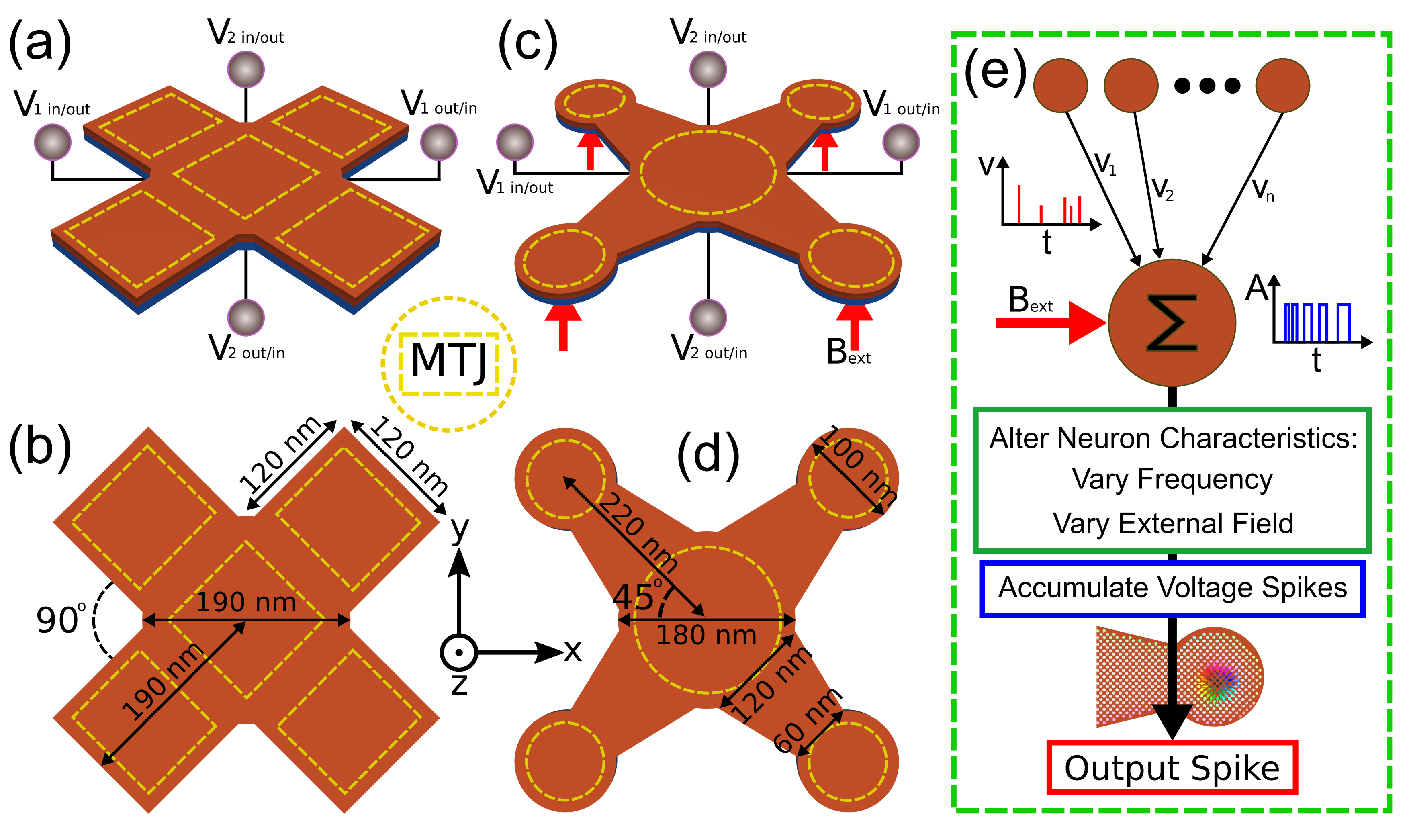
Free planar motion is achieved through the pulsing of current at high frequency in directions orthogonal to each other. This then forms a basis and the almost linear response of skyrmion velocity to applied current is exploited to derive the required vectors. The setup of the two devices is shown in Fig. 1. The first device, Fig. 1 (a), is a skyrmion configurable logic gate (SCLG) and the second, Fig. 1 (c), a skyrmion configurable neural network (SCNN) node based on the work of Xing Chen et al. [15]. Detailed explanations of their form and function will follow after we explore the theory of 2D motion.
II Skyrmion motion theory
We apply the Thiele [12] approach to the dynamics of our skyrmionic magnetisation textures assuming the stationary limit, where the magnetisation texture moves with constant velocity, and assuming that the texture does not deform. We consider the current in plane (CIP) geometry using the Zhang-Li model [16]. The travelling wave ansatz, , is then applied to the Landau-Lifshitz-Gilbert [17] dynamical equation with torque to produce [18, 19, 20] Thiele’s equation [12].
| (2) |
here is the gyrocoupling vector, is the dissipative tensor with components
| (3) |
is the velocity of the centre of mass of the skyrmion, is the current vector, is the Gilbert damping constant and is the dissipative spin transfer torque parameter. For an axially symmetric texture the dissipative tensor will have components and , for [21].
Solving Thieles equation, given , we get
| (4) | |||
| (5) |
If we now solve for two orthogonal currents, and , it is clear that the product of the resulting velocity vectors is zero.
We know that above the de-pinning threshold the current velocity relationship of skyrmions is close to linear [22, 23] and that if we reverse the the current flow we reverse the direction of motion [24]. We therefore measure the skyrmion velocity for two different current magnitudes, here A m-2 and A m-2, in both the and directions and derive unit vectors and average velocity per A m-2. From these values, assuming linearity at the current levels applied, we can calculate a current magnitude and time required in each direction of current application, and . The currents are then applied divided by the time-steps taken, here we switch the current at 200 MHz [8], to arrive at a prescription for moving a skyrmion too a specific point in the plane. As the deflection caused by the skyrmion Hall effect is included in the derived vectors it can effectively be ignored. This process will work for any topological degree, Eq. (1), of skyrmion including skyrmion bags [25, 26] and other higher degree skyrmions as the variation in Hall deflection makes no difference for this closed system.
As the currents are pulsed in two separate directions the maximum attainable velocity is approximately half of the velocity attainable with current pulsed in a single direction. This can be reduced if steps are taken to optimise the velocity by increasing pulse magnitude and decreasing pulse time for the shorter vector direction however we do not explore this here.
We use the graphics processing unit (GPU) enabled micromagnetic solver Mumax3 [27] to test our model by applying current in the cardinal and intercardinal directions, , and for distances in the range nm in steps of nm. Simulation parameters are given in the appendix. We find that the predicted directions vary by less than 2% and the distances by less than 1%.
III Skyrmion configurable devices
To demonstrate the effectiveness of this paradigm we simulate two different basic devices that use 2D skyrmion motion. These devices are designed such that they could be built into digital or analogue architectures as the primary required inputs are current magnitude and pulse duration and the outputs are current from the activation of magnetic tunnel junction (MTJ) switches. MTJ’s can detect quantised changes in resistivity due to the presence of skyrmions [28] and are considered ideal for the electrical detection of skyrmions. The ability to be deployed in analogue or digital architectures is important for use in neuromorphic applications and in solely analogue for use in high radiation environments such as fusion reactors and in space. We call them configurable as both the SCLG and the SCNN could be configured in the field to fulfil a number of roles.
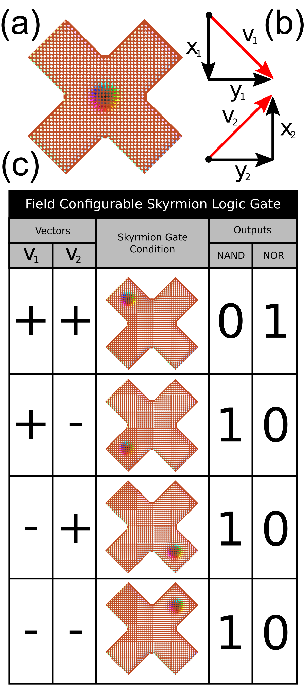
The SCLG can be preconfigured with a given logic gate configuration with each current pairing giving a different vector to a distinct MTJ, see Fig. 2, and each MTJ configured to provide a current response. We illustrate this in Fig. 2 (c), providing examples of NAND and NOR, the universal logic gates. This is a very simple device, theoretically ideal for production en masse in a large scale field programmable processor.
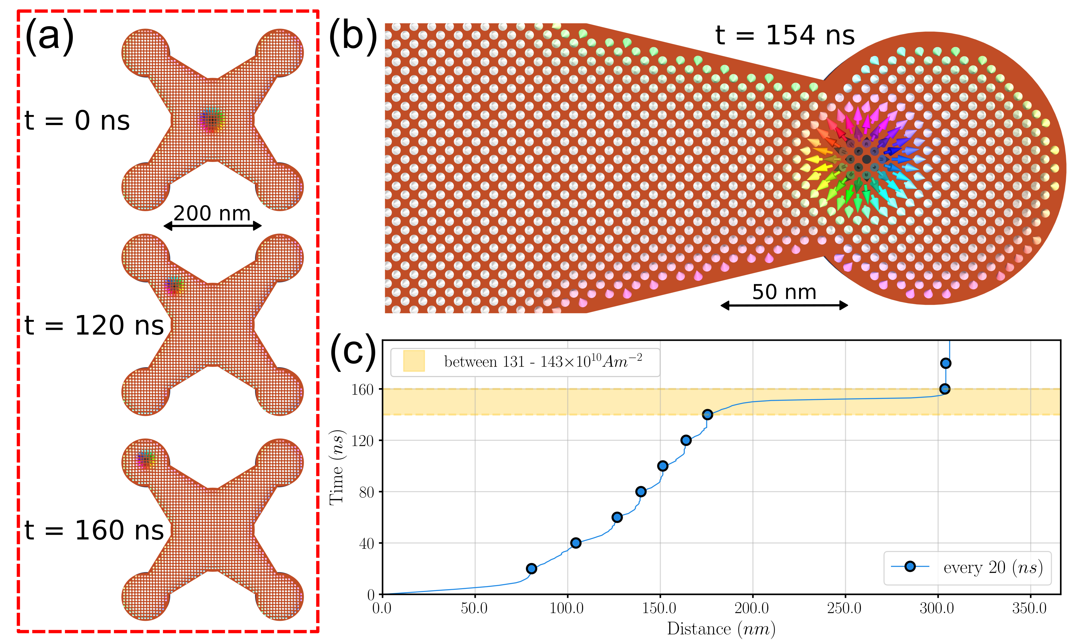
The SCNN, see Fig. 3, is designed in a similar fashion to the SCLG and features four arms with MTJ detectors. This design requires additional external control in the form of an accumulator for the input currents, see Fig. 1 (e). The skyrmion is driven by the accumulated currents from many pre-synaptic SCNN’s until sufficient current is present to drive the skyrmion through the edge repulsion barrier that is the constriction at the end of the arm prior to the MTJ disc. This simulates the leaky–integrate-fire (LIF) spiking model of neurons [29, 30] . Only one arm of the device can be utilised during any one activation sequence and each arm can provide a different activation profile by tuning the externally applied field, see Fig. 1 (c).
Both devices feature MTJ’s at their centres in order to detect the base state. In both cases the skyrmion can be driven, by an opposing applied pulse current, back to that base state. In the case of the SCNN this must be done to push the skyrmion from the MTJ activation site at the end of the arm as the constriction will not allow free passage. Once the skyrmion is free from the MTJ disc in the SCNN case and after activation in the SCLG case the skyrmion will return to the center of each device with no further applied current as this is the lowest energy state, this is however much slower than driving the skyrmion to the center. In both cases the returning current is lower than the activation current as the edge repulsion acts to drive the skyrmion toward the lowest energy state.
IV Discussion
We have shown that skyrmions can be driven with fine control in 2D. This extra dimension allows us to reconsider the design of many proposed skyrmionic devices. We use this 2D control to demonstrate skyrmion based configurable logic gates that could then be deployed in more complex information processing circuits. We also showed a configurable neural network node device that could have it’s firing activation functions altered and could simulate four separate neurons at distinct times. These devices where chosen so that a complete next generation computing architecture could be considered, drawing from classical computing and neuron inspired brain-like computing.
One motivation behind this work was the authors attempt to drive skyrmions down arbitrarily shaped tree like structures that could be used to represent the dendritic arbors of a typical human neuron. In conclusion we hope that the shift from 1D to 2D skyrmionic motion will enable a new perspective in the application of skyrmions to modern and future data, logic and brain-like applications.
V Appendix
We consider skyrmionic structures in thin film multilayers where the interfacial DMI results in Néel type skyrmions. The simulations where performed using the GPU-accelerated micromagnetic simulation program MuMax3 [27] with Landau-Lifshitz dynamics in the form
| (6) |
where rad(ns T)-1 is the electron gyromagnetic ratio, the dimensionless damping parameter, the effective field and the magnetisation vector field normalised by the saturation magnetisation.
The simulations external geometry is a nm2 rectangle of nm thickness, in order to represent a typical surface that could be fabricated using lithographic processing. Cell size of nm3 has been used. Material parameters are: saturation magnetisation kAm-1, exchange pJm-1, interfacial DMI mJm-2 and uniaxial anisotropy along the direction MJm-3 [31].
The applied current is of Zhang-Li [16] (CIP) type, the non-adiabacity of spin transfer torque constant is set to , current flows in the and directions at separate times:
| (7) | ||||
| (8) |
where A m-2 is the current density, the Bohr magneton and the saturation magnetisation expressed in Tesla.
Acknowledgements
This work was supported by the Engineering and Physical Sciences Research Council (EPSRC) grant EP/M506473/1. The Titan V GPU used for parts of this research was donated by the NVIDIA Corporation.
References
- Bogdanov and Hubert [1994] A. Bogdanov and A. Hubert, Thermodynamically stable magnetic vortex states in magnetic crystals, Journal of Magnetism and Magnetic Materials 138, 255 (1994).
- Fert et al. [2013] A. Fert, V. Cros, and J. Sampaio, Skyrmions on the track, Nature Nanotechnology 8, 152 (2013).
- Zhang et al. [2015] X. Zhang, M. Ezawa, and Y. Zhou, Magnetic skyrmion logic gates: Conversion, duplication and merging of skyrmions, Scientific Reports 5, 9400 (2015).
- Chen et al. [2020] R. Chen, Y. Li, V. F. Pavlidis, and C. Moutafis, Skyrmionic interconnect device, Physical Review Research 2, 043312 (2020).
- Song et al. [2020] K. M. Song, J.-S. Jeong, B. Pan, X. Zhang, J. Xia, S. Cha, T.-E. Park, K. Kim, S. Finizio, J. Raabe, J. Chang, Y. Zhou, W. Zhao, W. Kang, H. Ju, and S. Woo, Skyrmion-based artificial synapses for neuromorphic computing, Nature Electronics 3, 148 (2020).
- Grollier et al. [2020] J. Grollier, D. Querlioz, K. Y. Camsari, K. Everschor-Sitte, S. Fukami, and M. D. Stiles, Neuromorphic spintronics, Nature Electronics 3, 360 (2020).
- Parkin et al. [2008] S. S. P. Parkin, M. Hayashi, and L. Thomas, Magnetic Domain-Wall Racetrack Memory, Science 320, 190 (2008).
- Woo et al. [2018] S. Woo, K. M. Song, X. Zhang, Y. Zhou, M. Ezawa, X. Liu, S. Finizio, J. Raabe, N. J. Lee, S.-I. Kim, S.-Y. Park, Y. Kim, J.-Y. Kim, D. Lee, O. Lee, J. W. Choi, B.-C. Min, H. C. Koo, and J. Chang, Current-driven dynamics and inhibition of the skyrmion Hall effect of ferrimagnetic skyrmions in GdFeCo films, Nature Communications 9, 959 (2018).
- Zhang et al. [2016] X. Zhang, Y. Zhou, and M. Ezawa, Antiferromagnetic Skyrmion: Stability, Creation and Manipulation, Scientific Reports 6, 24795 (2016).
- Jiang et al. [2017] W. Jiang, X. Zhang, G. Yu, W. Zhang, X. Wang, M. Benjamin Jungfleisch, J. E. Pearson, X. Cheng, O. Heinonen, K. L. Wang, Y. Zhou, A. Hoffmann, and S. G. E. te Velthuis, Direct observation of the skyrmion Hall effect, Nature Physics 13, 162 (2017).
- Gnoli et al. [2021] L. Gnoli, F. Riente, M. Vacca, M. Ruo Roch, and M. Graziano, Skyrmion Logic-In-Memory Architecture for Maximum/Minimum Search, Electronics 10, 155 (2021).
- Thiele [1973] A. A. Thiele, Steady-State Motion of Magnetic Domains, Physical Review Letters 30, 230 (1973).
- Dzyaloshinsky [1958] I. Dzyaloshinsky, A thermodynamic theory of “weak” ferromagnetism of antiferromagnetics, Journal of Physics and Chemistry of Solids 4, 241 (1958).
- Moriya [1960] T. Moriya, Anisotropic Superexchange Interaction and Weak Ferromagnetism, Physical Review 120, 91 (1960).
- Chen et al. [2018] X. Chen, W. Kang, D. Zhu, X. Zhang, N. Lei, Y. Zhang, Y. Zhou, and W. Zhao, A compact skyrmionic leaky–integrate–fire spiking neuron device, Nanoscale 10, 6139 (2018).
- Zhang and Li [2004] S. Zhang and Z. Li, Roles of Nonequilibrium Conduction Electrons on the Magnetization Dynamics of Ferromagnets, Physical Review Letters 93, 127204 (2004).
- Gilbert [2004] T. Gilbert, A phenomenological theory of damping in ferromagnetic materials, IEEE Transactions on Magnetics 40, 3443 (2004).
- Thiaville et al. [2005] A. Thiaville, Y. Nakatani, J. Miltat, and Y. Suzuki, Micromagnetic understanding of current-driven domain wall motion in patterned nanowires, EPL (Europhysics Letters) 69, 990 (2005).
- Everschor et al. [2011] K. Everschor, M. Garst, R. A. Duine, and A. Rosch, Current-induced rotational torques in the skyrmion lattice phase of chiral magnets, Physical Review B 84, 064401 (2011).
- Elías et al. [2017] R. G. Elías, N. Vidal-Silva, and A. Manchon, Steady motion of skyrmions and domains walls under diffusive spin torques, Physical Review B 95, 104406 (2017).
- Huber [1982] D. L. Huber, Dynamics of spin vortices in two-dimensional planar magnets, Physical Review B 26, 3758 (1982).
- Iwasaki et al. [2013] J. Iwasaki, M. Mochizuki, and N. Nagaosa, Universal current-velocity relation of skyrmion motion in chiral magnets, Nature Communications 4, 1463 (2013).
- Tomasello et al. [2014] R. Tomasello, E. Martinez, R. Zivieri, L. Torres, M. Carpentieri, and G. Finocchio, A strategy for the design of skyrmion racetrack memories, Scientific Reports 4, 6784 (2014).
- Wang et al. [2022] W. Wang, D. Song, W. Wei, P. Nan, S. Zhang, B. Ge, M. Tian, J. Zang, and H. Du, Electrical manipulation of skyrmions in a chiral magnet, Nature Communications 13, 1593 (2022).
- Foster et al. [2019] D. Foster, C. Kind, P. J. Ackerman, J.-S. B. Tai, M. R. Dennis, and I. I. Smalyukh, Two-dimensional skyrmion bags in liquid crystals and ferromagnets, Nature Physics 15, 655 (2019).
- Kind and Foster [2021] C. Kind and D. Foster, Magnetic skyrmion binning, Physical Review B 103, L100413 (2021).
- Vansteenkiste et al. [2014] A. Vansteenkiste, J. Leliaert, M. Dvornik, M. Helsen, F. Garcia-Sanchez, and B. Van Waeyenberge, The design and verification of MuMax3, AIP Advances 4, 107133 (2014).
- Guang et al. [2023] Y. Guang, L. Zhang, J. Zhang, Y. Wang, Y. Zhao, R. Tomasello, S. Zhang, B. He, J. Li, Y. Liu, J. Feng, H. Wei, M. Carpentieri, Z. Hou, J. Liu, Y. Peng, Z. Zeng, G. Finocchio, X. Zhang, J. M. D. Coey, X. Han, and G. Yu, Electrical Detection of Magnetic Skyrmions in a Magnetic Tunnel Junction, Advanced Electronic Materials 9, 2200570 (2023).
- Abbott [1999] L. F. Abbott, Lapicque’s introduction of the integrate-and-fire model neuron (1907), Brain Research Bulletin 50, 303 (1999).
- Hodgkin and Huxley [1990] A. L. Hodgkin and A. F. Huxley, A quantitative description of membrane current and its application to conduction and excitation in nerve, Bulletin of Mathematical Biology 52, 25 (1990).
- Kind et al. [2020] C. Kind, S. Friedemann, and D. Read, Existence and stability of skyrmion bags in thin magnetic films, Applied Physics Letters 116, 022413 (2020).