A Novel Two-Layer DAG-based Reactive Protocol for IoT Data Reliability in Metaverse
Abstract
Many applications, e.g., digital twins, rely on sensing data from Internet of Things (IoT) networks, which is used to infer event(s) and initiate actions to affect an environment. This gives rise to concerns relating to data integrity and provenance. One possible solution to address these concerns is to employ blockchain. However, blockchain has high resource requirements, thereby making it unsuitable for use on resource-constrained IoT devices. To this end, this paper proposes a novel approach, called two-layer directed acyclic graph (2LDAG), whereby IoT devices only store a digital fingerprint of data generated by their neighbors. Further, it proposes a novel proof-of-path (PoP) protocol that allows an operator or digital twin to verify data in an on-demand manner. The simulation results show 2LDAG has storage and communication cost that is respectively two and three orders of magnitude lower than traditional blockchain and also blockchains that use a DAG structure. Moreover, 2LDAG achieves consensus even when 49% of nodes are malicious.
Index Terms:
Data Reliability, Graph, Hash, Signaling, Distributed agreement.I Introduction
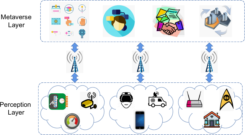
The Metaverse is poised to transform the Internet by closely coupling the digital and physical world [1], whereby digital twins (DTs) are used to represent a physical object/entity such as a person or machine or an entire factory. To do that, DTs require data from devices operating in Internet of things (IoT) networks. For example, a device may collect health data from a person, which is then used by his/her digital twin [2]. Indeed, an IoT network forms a bridge between the physical world and the Metaverse. This is illustrated in Fig. 1, where devices operating at the perception layer gather and send information via gateways to the Metaverse layer. The DTs then use collected data to model and simulate a physical entity/process. Further, these DTs may then initiate smart contracts based on received data [3].
Data reliability is thus a key concern to any users or DTs. This is especially critical when DTs are relied upon for decision making; e.g., an operator may conduct simulations using DTs to determine how resources are to be allocated in a factory or when machines are to undergo maintenance. Further, users/DTs may wish to audit collected data, which requires data to be traceable, immutable and transparent [3].
One possible solution is to employ blockchain, where DTs leverage features such as immutability, traceability and integrity [4]. Consequently, a number of works have applied blockchain for secure data and information exchanges [5]. An example work is [6], which uses blockchain to provide end-to-end data integrity in a supply chain.
Unfortunately, blockchain has a number of scalability issues that limit its use on IoT devices [7]. Firstly, its storage requirement is significant, where each participating node needs to store a copy of the entire blockchain. For example, the size of the Bitcoin blockchain exceeds 380 GB in 2022 [8] and the size of the Ripple blockchain, aka XRP ledger, is more than 14 TB [9]. Secondly, its transaction throughput is limited, which relates to the speed in which data is written into a block. For example, the average number of transactions processed by Bitcoin and Ethereum is respectively seven and 15 per second [10]. Thus, it is not suitable for applications that generate frequent transactions. Thirdly, its communication cost is significant, where an entire blockchain is sent to all participating nodes. For example, a Bitcoin node may upload more than 200 GB data per month [11]. Lastly, we note that a key reason why blockchain has a high resource requirement is that it uses proactive consensus protocols. This means nodes spend resources to verify data via a consensus protocol even when a transaction or data is not used by participants. Hence, all participants must store sufficient information to verify the data generated by other participants, which leads to high storage and communication overhead.
To this end, we design a novel distributed approach, called a two-layer directed acyclic graph (2LDAG), to ensure data reliability in IoT networks. Briefly, each IoT node only stores its generated data and corresponding hash values, and those of its neighbors. Nodes only send and receive hashes to and from their neighbors, and they can generate proofs in parallel. The proofs form a DAG, linking all data in an IoT network. In addition, we propose a novel proof-of-path (PoP) protocol that allows any node to trace and verify the data of a source node. Advantageously, it is a reactive consensus protocol, meaning the data verification process is only initiated when a node needs to verify the data from a source node. In a nutshell, the contributions of this paper are as follows:
-
•
It proposes an architecture, called 2LDAG, that ensures the integrity and reliability of IoT data. It embodies the following advantages over blockchain based solutions: improved storage, communication and throughput.
-
•
It proposes a novel PoP protocol that operates in a reactive and distributed manner, and operates correctly even when a large number of malicious nodes exist.
-
•
It shows 2LDAG is secure against majority, Sybil, denial of service (DoS), eclipse and selfish attacks.
-
•
It presents the first study of 2LDAG. Simulation results show that the storage and communication requirements of 2LDAG are two and three orders of magnitude lower than blockchain based solutions.
II Related Works
The reliability of data in IoT or wireless sensor networks (WSNs) has been of interest for decades [5]. Traditional solutions leverage message authentication codes [12] or public key infrastructures [13] to ensure data integrity. However, these solutions are centralized, which motivate the development of decentralized solutions such as blockchain [5].
To this end, we only review blockchain works that consider resource constrained nodes. Specifically, we first review solutions that lower the storage and communication requirements of blockchain, and improve its throughput. We then discuss consensus protocols designed for IoT networks.
II-A Blockchain Scalability
Works that seek to scale blockchain have proposed light nodes, pruned nodes, sharding, coded blockchains and DAG [7]. The following paragraphs review their main ideas and limitations.
Nakamoto [14] proposed so called light nodes that only store block headers. However, light nodes rely on full nodes to store the entire blockchain and to verify data. Although light nodes have a lower storage requirement, Nakamoto’s approach leads to data avaliability attacks [15].
Pruned nodes remove information that is unnecessary for generating new blocks. For example, the nodes in [14] remove unspent transaction outputs (UTXO), which is only utilized in one transaction and not used for block creation. However, both light and pruned nodes permanently delete data, meaning it is no longer possible to track the origin of blockchain data.
Sharding [16] is a scheme whereby participants are divided into so called shards. Each shard maintains an independent sub-chain, and thus the participants in each shard have a comparatively lower storage requirement and higher throughput as compared to the conventional blockchain, especially with more shards. However, cross-shard activities require additional signaling complexity. Moreover, it sacrifices security due to the smaller number of participants in each shard.
Coded blockchains [17] leverage error correction codes to encode blockchain data and store them at participants in a distributed manner. However, coded blockchains require extra computations for encoding and decoding. Moreover, there is a probability that an encoded block is not decodable [17].
DAG blockchain [18] changes the structure of blockchain from a chain to a graph. Consequently, transactions do not need to queue at the end of the chain, which significantly improves blockchain throughput. An example DAG blockchain is IOTA or Tangle [19]. Each transaction in IOTA verifies two previously generated transactions. There are no ‘miner’ nodes where they generate transactions freely and simultaneously. However, DAG blockchain nodes need to store the entire graph, i.e., the blockchain, to validate blocks generated by other nodes. Hence, it is not suitable for IoT devices with limited storage space.
II-B Consensus Protocols
Consensus protocols help nodes agree on information in a distributed manner even when some nodes are malicious or dishonest. For a comprehensive survey of consensus protocols, the reader is referred to [20]. Here, we will only discuss consensus protocols that are suitable for resource-constrained devices. They either use a proof based mechanism or practical byzantine fault tolerance (PBFT) protocols.
Proof-of-stake (PoS) [21] miners compete to generate blocks based on their stakes rather than computation power unlike PoW. Hence, PoS is suitable for IoT applications that use monetary rewards, which can be used as ‘stakes’. In proof-of-elapsed-time (PoET) [22], a node generates a block with a minimum random waiting timer. However, the verification in PoET requires a trusted execution environment. Such an environment is usually deployed on specific hardware, which is not suitable for a wide range of IoT applications [21].
PBFT based consensus protocols have high throughput, low latency and low computational overhead, which make them desirable for IoT networks [20]. However, conventional PBFT has high communication overheads due to its three phases negotiation process. To this end, many works have seek to reduce the said communication overheads. For example, the work in [23] proposed HoneybadgerBFT, which leverages error correction codes to reduce communication overhead when propagating blocks when using PBFT. They, however, incur extra computational complexity.
II-C Discussion
Existing blockchain scalability solutions have not jointly reduced storage, communication and computation cost whilst guaranteeing a sufficient level of throughput and security for IoT applications. A key reason is that these blockchains use proactive consensus protocols, where nodes must reach consensus on generated data. Inspired by the immutability, reliability and traceability features of blockchain, in the following section, we introduce 2LDAG and PoP.
III 2LDAG Architecture
2LDAG has a physical layer and a logical DAG layer. At the physical layer, nodes maintain a list of neighbors, construct data blocks using generated data, and transmit/receive hashes to/from their neighbors. The logical layer interconnects data blocks, whereby the hash of data blocks forms a DAG. This DAG is used to verify a data block.
III-A Physical Layer
We model an IoT network as a graph . It has a set of static nodes inter-connected by an un-directed edge in the set . Each node is indexed by , and at most nodes are malicious. Note, we do not consider trust management, where we assume there is a complementary method to register a device onto a network. Each edge is denoted as , where . For node , its neighbors set is
| (1) |
All nodes have topological information, i.e., they know . Each node generates data at a rate of bit/s. We emphasize that nodes only store their generated data; i.e., a node does not forward its data to any other nodes in . We use to denote the storage capacity of node .
Nodes store their generated data in so called data blocks, each of which has two segments: body and header. The body segment stores the data collected by a node and has a constant size of bits. This means node generates a data block every seconds. The header segment contains data used to maintain the logical layer; see details in Section III-B.
We use to indicate the -th data block generated by node ; we also use to denote the generation time of . Let and denote the header and body of , respectively. Node records all its data blocks in the set .
After node generates data block , it transmits the corresponding digest to all its neighbors in , where denotes a hash function. The data generation process at nodes will be presented in Section III-D.
III-B Data Block Structure
The data block structure used by nodes is shown in Fig. 2. A block header consists of the following fields:
-
•
Version is used to track changes and updates to the 2LDAG architecture and protocol. It has size .
-
•
Time records the generation time of a data block. We use to denote its size.
-
•
Root corresponds to a Merkle tree root. Its size is , which is also the hash size.
-
•
Digests record hashes that node has received from its neighbors, i.e., , and the hash of its previous data block, i.e., . The size of this field is , where ; note, denotes the cardinality of a set.
-
•
Nonce is a number that ensures the hash of version, time, root, digest and nonce meets a given difficulty level. This difficulty is chosen such that a device can find a suitable nonce quickly, see details in Section III-D. Its size is .
-
•
Signature is calculated using a public-private key scheme. Each node has public key and private key . Let and denote respectively an encryption and decryption function. We can apply a low complexity encryption scheme; e.g., the one proposed in [24] for smart home applications. Let be the fields in a block header. The signature field contains . The size of is .
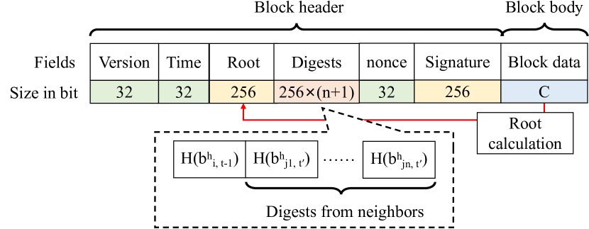
Given that a block body has sampled data only, and has size bits, the total size of a data block at node is
| (2) |
where is a constant defined as
| (3) |
III-C Logical Layer
Define as a DAG, where the set of data blocks is . The set contains directed edges that connect data blocks. There is an edge in if data block header contains the digest of block header . We call a parent of , and a child of . In this paper, if the context is clear, we omit and write as .
Define a path from data block to as
| (4) |
where , and is the path length. For any two adjacent data blocks and in path , data block is a parent of . Further, we say data block is a descendant of . We then say node points to block if data block in node is a descendant of .
III-D Data Block Generation
At network initialization, i.e., , each node generates a genesis block; . Then, node calculates the digest and transmits it to each neighbor node in . Once node receives the digest from neighbor , node constructs a set , which contain the latest digest from each neighbor in ; note, we have .
Given bits of data, node constructs data block . In the header of , node records the version and time, and calculates root , where is a Merkle tree root function. It then includes in the Digests field, denoted by , the digests received from its neighbors as well as the digest of its previous data block ; i.e., we have . Next, node determines a nonce that satisfies
| (5) |
where is a small fixed difficulty level such that nodes can find a suitable quickly, e.g., in seconds. After that, node calculates the Signature field using Version , Time , Root , Digests and Nonce . Formally,
| (6) |
Lastly, node transmits the digest to all its neighbors in and appends data block to its storage . After neighbor receives digest from node , it updates the set by replacing with .
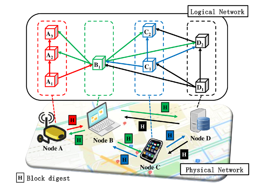
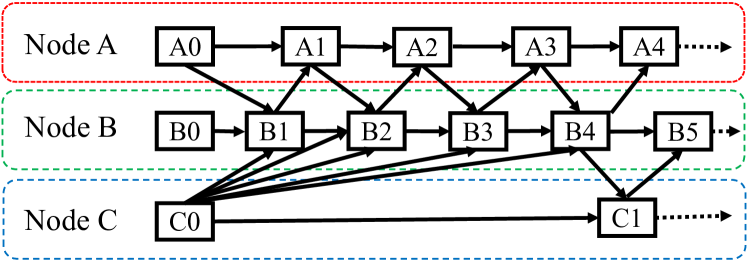
We now use an example to illustrate 2LDAG. Referring to Fig. 3, there are four physical nodes , , , and . Their neighbors set is respectively , , and . Assume node first generates a block, say . It transmits digest to node and . When node generates a block say , it contains the digest from node . Node then transmits digest to node and . Similarly, digest is sent to node after node generates block . Hence, block generated by node includes digests and . As shown in Fig. 3, the corresponding digests stored in these blocks form a DAG. Observe that each node only stores data blocks generated by itself and transmits only block digests. For example, node only stores data block in its local storage, and the communication cost of node relates to the transmission and reception of three digests to and from nodes , , and , respectively. This explains why 2LDAG has a low storage and communication cost.
IV Proof-of-Path Protocol
A PoP process is initiated when a node, say , needs to verify the content of a block stored at say node , namely . We call node a validator, and node a verifier. Node first retrieves block from node , which includes the block header and block body . Using the said DAG, node aims to identify a set of nodes that are then stored in the set ; these nodes contain a block that points to block . Consensus of block is reached once the following condition is satisfied: , where is the number of tolerable malicious nodes. In other words, there is a path containing at least nodes that agree on the integrity of block .
Initially, we have and . Define the last added block on path as a verifying block, denoted by , which is initially set to . To update the above sets, let be a child data block of . The validator then retrieves the corresponding block header and checks whether the value is in . If yes, the validator makes the following updates: (1) add block to , (2) add node to , and (3) replace with .
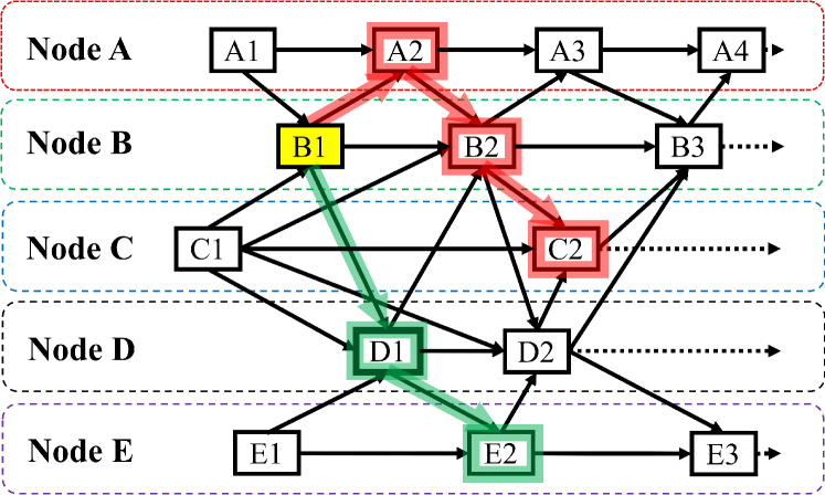
To illustrate PoP, consider Fig 4. Consider , meaning consensus is reached if there are three nodes in . Assume nodes , , and are neighbors of each other. Node ’s only neighbor is node and node only neighbor is node . Assume there is a request to verify block . Then two possible paths are and . Both paths contain three disjoint nodes, meaning there are nodes that directly or indirectly verify the integrity of block . Hence, consensus is reached if a validator constructs any of these two paths. However, path is longer, which means a validator that chooses path needs to retrieve an additional data block header.
We next propose an algorithm to reduce the total number of block headers retrieved by a validator when selecting the next verifying node of data block .
IV-A Weighted Path Selection (WPS)
There are two cases to consider when selecting a verifying node . In case-1, if a validator node selects a block stored in a node that has been included in then does not contribute to the consensus of block . Hence, the validator node needs to select a node that is not in . In case-2, all neighbors of node may be already in , then selecting any neighbor has the same effect.
To this end, we introduce a weight for node . Here, is defined as the fraction of node neighbors that is not included in , i.e.,
| (7) |
Node then selects a with the minimum value. Mathematically,
| (8) |
If multiple neighbors have the same weight, the algorithm selects the one not in .
The pseudocode of WPS is shown in Algorithm 1. Its inputs include , and . Its output is a node that stores the child of to be included on path . Node first calculates weight using Eq. (7) for each ; see lines 1-1. It then selects the node with the minimum weight and adds it into a set of candidate nodes ; see line 1. If there is only one node , then it returns node ; see lines 1-1. If we have , there are two cases: 1) if or , then all nodes in can be selected, or 2) if , then node selects one in ; see lines 1-1.
We now use Fig. 4 to illustrate WPS. When determining the next verifying block or node of , calculate the weight of node ’s three neighbors to yield , and . Note that node does not have a block that is a child of , and node has the minimum weight. Hence, we choose as the second block to be added onto the path at the validator. Next, when determining the verifying block or node of , we obtain the weight of its neighbors as , and . We choose because node exists in .
IV-B Trust Path Selection (TPS)
From the example in Fig. 4, we see that one may need to obtain and again when it verifies block . This wastes both computation and communication resources. To this end, we require a node, say , to store block headers that it has verified in a set . Then, node is able to directly construct a path using the blocks in . This is carried out via a TPS algorithm, which is detailed next.
A validator node can verify block directly if its child block header is in the set , i.e.,
| (9) |
where is a child block of the block . The validator node can then update the verifying block to , add block to the set and path .
Algorithm 2 details TPS. It iteratively updates using the data block headers in . It returns the updated set , and until no block headers in contain .
IV-C Putting It All Together
We now discuss the procedures performed by a validator node and a responder node. Here, a responder node is defined as a node that sends information to a validator node in order to verify block .
Validator: The pseudocode of a validator is shown in Algorithm 3. Assume validator aims to verify block . It first retrieves from node , which is also called the verifier. It then calculates the Merkle tree root and checks it against the header . If there is inconsistency, i.e., does not equal , PoP returns an error. Here, GetRoot() returns the value in the Root field in the block header of . Otherwise, in line-3 Algorithm 3, validator makes the following settings: , and the verifying block is set to .
Next, using the header of block , validator calculates digest and constructs the set and using the set as per TPS. If consensus is not reached, i.e., , the validator finds the next block for path and adds a new node into the set . Specifically, it calls WPS to find the next verifying node of data block ; WPS finds a node to verify block . After identifying node , validator transmits a REQ_CHILD message to node containing ; see line-3.
Once validator receives a RPY_CHILD message from node within timeout , see line-3, it extracts from the message; see line-3. It then calculates and checks the digest stored in . The function GetDigest() returns the digest of node from block header . If the above two digests are consistent, i.e., , then node points to block . Thus, validator adds node into the set and adds block index to the path . It then sets the verifying block to . Next, validator calls TPS to continue constructing the path; see line-3. Otherwise, if the digests are not consistent or node does not reply, node removes from and selects another node to send a REQ_CHILD message. If validator fails to receive a valid RPY_CHILD message from all nodes in , which is initialized to in line 3, it rolls back to the previous verifying block and sends REQ_CHILD message to nodes other than ; see lines 3-3. To do this, it removes from , and also from , which is initilized as in line 3. Note that the set is a stake because the path in DAG has no loop. The validator then pops out , which is the peak item, from and sets verifying block to the block at the peak of updated . If the validator rolls back to the first block on the path, i.e., the verifier block , and unables to receive a valid RPY_CHILD message, i.e., , Algorithm 3 returns an error. In contrast, if it receives a valid RPY_CHILD message, it sets and continues to construct the set and . Upon reaching consensus, i.e., , validator stores the block header for all blocks in into the set ; see line-3.
Responder: The pseudocode of a responder is shown in Algorithm 4. It finds a block in whereby its block header contains . It then sends the validator a message containing . Formally, node finds a subset of child blocks where
| (10) |
One or more blocks may contain the digest , i.e., . This is because nodes generate data blocks at different rates. If a node has a higher rate, its neighbor may include the digest in multiple blocks. For example, as shown in Fig. 3, the digest of is included in both and . To this end, node needs to select the oldest generated block where
| (11) |
After that, node transmits a RPY_CHILD message with to validator .
IV-D Discussion
Here, we provide some discussion on security concerns at the application layer. For attacks/concerns at other layers of the protocol stack, we refer the reader to well-known attacks and defenses in the literature, e.g., [25]. We note that the registration and authentication of nodes are beyond the scope of this paper. The reader is referred to works such as [26] for authentication/security protocols. Lastly, we remind the reader that nodes have a public-private key pair, and they are aware of the topology and each other’s public key.
IV-D1 Malicious Nodes
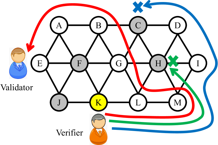
Recall that in Section IV-C, if validator does not receive or receive an invalid RPY_CHILD message from within the timeout , it requests a RPY_CHILD message from another node in . If all nodes in fail to reply, validator creates a path that does not involve node ; see Algorithm 3, lines 3-3. Consider Fig. 5. Assume validator aims to verify a block at verifier . Malicious nodes are denoted by gray circles. In this example, to ensure consensus, the resulting path must contain at least seven nodes. After attempting to construct the green and blue path, the validator eventually constructs the red path.
IV-D2 Majority Attack
In conventional blockchains, assuming proof-of-work (PoW), attackers with the majority of the computational power, i.e., 51%, are able to corrupt blockchain content. This is because they are able to construct the longest chain containing invalid data, which is then accepted by participants. In contrast, in 2LDAG, a node will never replace its blocks from those of other nodes. Specifically, nodes maintain their own blocks and they are not required to maintain a globally consistent ’chain’.
An attacker may cause all nodes in or the path to contain many malicious nodes. In this case, a solution is to increase the value of , meaning more nodes will be required to reach consensus.
IV-D3 Sybil Attack
A Sybil attacker creates fake nodes, which can then be used to launch a 51% attack for example. Recall that a validator, say , constructs a set with unique nodes. This means a Sybil attacker that replicates the same malicious nodes does not have an impact on the consensus process. Moreover, all nodes store the topology and they are able to use the public key of nodes to verify their identity. Both facts prevent a Sybil attacker from adding nodes undetected.
IV-D4 Man-in-the-Middle Attack
We only consider an attacker that aims to corrupt data block headers and/or body. For an eavesdropping attack, a sender can encrypt its messages using its private key or derive a symmetric key based on its private key; see [27] for an example. An attacker could also drop messages between a source and destination pair. To this end, we can employ multiple paths to bypass an attacker [28].
In 2LDAG, data block corruption is avoided as follows. The data block header sent from a node, say , is signed using its private key . A validator can validate this data block using the corresponding public key . This prevents manipulation by an intermediate node. Further, blocks are inter-connected in a DAG. This means any change to a block will impact the digest of subsequent block(s) in the DAG.
IV-D5 Denial of Service (DoS) Attack
A malicious node may attempt to generate many digests and floods its neighbors. In 2LDAG, a node needs to solve a puzzle that causes it to take seconds to generate a block. Hence, a malicious is not able to generate a large number of blocks within a short time. This is the same strategy as IOTA [19]. Further, a node may ban a neighbor that generates blocks quicker than the expected time to solve the puzzle. We note that such a malicious node will only affect its direct neighbors. This is because the digests from a node are not flooded throughout a network.
In 2LDAG, nodes process the following messages: 1) REQ_CHILD, 2) RPY_CHILD, and 3) digest. These messages and digests can include a nonce to avoid replay attacks. Further, verifiers can authenticate a validator before replying to a REQ_CHILD message. Similarly, nodes only receive/forward/process digests, REQ_CHILD and/or RPY_CHILD messages from authenticated nodes. Otherwise, they can safely discard these digests/messages. This ensures the DAG and PoP involve only honest nodes.
Lastly, if a node is captured, hence becoming malicious, any changes to its data blocks will be detected by PoP. This is because the digest of its data blocks will not be consistent with that of its neighbors.
IV-D6 Selfish Attack
In PoP, a selfish node may never reply to a REQ_CHILD message. To prevent this, nodes can be equipped with a penalty mechanism. Each node maintains a blacklist consisting of nodes that do not reply to a REQ_CHILD message, either due to selfish behavior, disconnection or malicious. Then the block generated by the selfish node will not be verified by other nodes. The nodes in the blacklist will be removed after it helps transmit a certain number of blocks. Therefore, to show their willingness to participate after re-connection, nodes will actively transmit their data blocks.
V Performance Analysis
In this section, we analyze the storage and message overhead of 2LDAG and PoP. Briefly, our goal is to quantify the maximum amount of data stored by node at time , and the number of messages emitted and received by a validator during verification.
Proposition 1.
The total number of data blocks at time is .
Proof.
Recall that a node generates a data block every seconds. Hence, node has generated data blocks at time . Therefore, the total number of data blocks is . ∎
Recall that nodes, say , maintain set in order to reduce communication cost. The following proposition bounds the size of .
Proposition 2.
At time , the size of is upper bounded by bits.
Proof.
Hence, we have the following proposition for node storage.
Proposition 3.
At time , the total storage at node is upper bounded by bits.
Proof.
From Algorithm 3, we analyze its message overhead, which is the number of messages sent/received by a validator. We first have the following proposition that quantifies the message overhead lower bound.
Proposition 4.
A validator node emits and receives at least messages to reach consensus when .
Proof.
When , the validator or node is not able to reach consensus using its stored information. This means it needs at least one REQ_CHILD and RPY_CHILD message exchange in order to verify block . Moreover, it needs to validate at least verifying blocks, and add disjoint nodes to , to reach consensus, i.e., . Hence, the validator emits and receives at least messages to reach consensus when . This completes the proof. ∎
Before discussing the message overhead upper bound incurred by a validator, we first highlight an interesting finding. Consider Fig. 6. Assume node has a much higher data generation rate than node . As a result, the digest of block exists in multiple blocks at node , and block only has the digest of block and . Further, assume . When a validator needs to verify a block, say , it needs to construct a path that traverse all three nodes. Notice that the size of set does not increase after adding the blocks in set into the path. This is because they involve nodes that exist in . Note also there is a micro-loop, namely , in the path. We use to denote a set of nodes that are traversed by a micro-loop. The number of blocks in a micro-loop is limited by the block generation time interval of a node not in , say node in Fig. 6. We then have the following proposition for the maximum number of blocks in .
Proposition 5.
Let be a set of nodes that is traversed by a micro-loop, then the number of blocks within a micro-loop is upper bounded by .
Proof.
Let be the maximum block generation time interval of nodes in , where
| (16) |
Let denote the number of blocks generated by node within time period , where
| (17) |
Therefore, the maximum number of blocks within a micro-loop is
| (18) |
∎
In terms of message overhead upper bound, we have the following proposition.
Proposition 6.
Let nodes be indexed by the descending order of their data generation rate, i.e., , and . Assume there are no malicious nodes. The total message overhead that a validator emits and receives is upper bounded by .
Proof.
Recall that a validator node reaches consensus if . It needs to construct a path , which may include a micro-loop traversed by at most nodes. Using Proposition-5, the maximum number of blocks within a micro-loop is . Then the length of path is upper bounded by
| (19) |
When a validator validates block on path , it sends at most REQ_CHILD messages, where . In addition, it receives at most RPY_CHILD messages, where of them are invalid as they are sent by malicious nodes. Therefore, the total message overhead of a validator satisfies
| (20) |
This ends the proof.
∎
VI Numerical Evaluation
The simulations are carried out on a desktop with an i7-12700 CPU and 32 GB RAM. We evaluate three key metrics: (1) storage overhead, which is the total disk space at a node, (2) communication overhead, which is the total amount of data a node transmits during block generation, and (3) time for consensus, which is the time that PoP uses to find a sufficient path to reach consensus. We compare the storage and communication overhead of 2LDAG with the PBFT blockchain[29], and the tokenless IOTA blockchain [19]. We set the size of Digests and Signature field respectively to bits. The Version, Time and Nonce field are set to bits. The physical network consists of 50 wireless IoT nodes in an area of 1000 square meters. All nodes have a communication range of 50 meters. To ensure a connected network, we place nodes one by one. That is, we start by randomly placing a node in the center of the said area. A new node is then added to the area with the condition that it is always placed randomly within the communication range of an already deployed node.
We divide time into slots. Each node generates at most one block in each time slot. When a node generates a block, it must verify another block that is generated in the past using PoP. This means a node is a validator when generating a data block. It should be noted that PoP can only verify a block that is generated before time slots. This is because to achieve consensus for a block, a validator needs to find a directed path that traverses more than physical nodes. This also means a path that passes more than time slots.
VI-A Storage Overhead
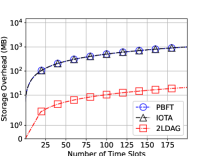
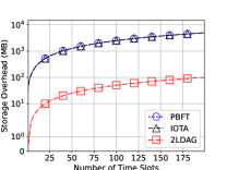
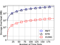
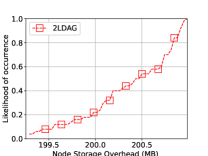
We first compare the average storage overhead of nodes in 2LDAG versus PBFT and IOTA. We evaluate the following block sizes (in MB): . From Fig. 7(a) to 7(c), we see that the node average storage overhead of 2LDAG is almost two orders of magnitude lower than PBFT and IOTA. Note, nodes have different block header sizes because they different number of neighbors. Hence, we show the Cumulative Distribution Function (CDF) of the storage at each node at 200 time slot in Fig. 7(d). We see that the storage level at nodes varies from 199 to 201 MB. Therefore, the number of neighbors does not have a significant impact on node storage.
VI-B Communication Overhead
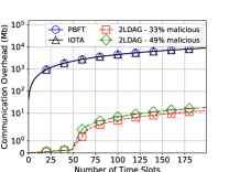
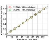
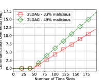
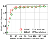
The block size is MB and each node generates one block at each time slot. We consider two possible number of malicious nodes, namely 33% and 49% of the total number of nodes are malicious. These values correspond to the number of tolerable malicious nodes in PBFT and IOTA or traditional blockchains such as Bitcoin. This means 2LDAG reaches a consensus with paths that contain 17 and 26 physical nodes. From Fig. 8(a), we see that the overall node average communication overhead of 2LDAG is almost three orders of magnitude lower than PBFT and IOTA. Note that the communication overhead of 2LDAG is almost zero in the first 50 time slots. This is because nodes start to validate other blocks after time slots. Moreover, the communication overhead of 2LDAG for consensus is much higher than DAG construction, see Fig. 8(b) and 8(c). This is because 2LDAG only transmits digests for block generation, but needs to transmit block headers for consensus. We see that 2LDAG which tolerates 49% malicious nodes has a higher communication overhead for consensus, because it needs to construct longer paths to achieve PoP consensus. Fig. 8(d) shows the CDF of the communication overhead for each node at 200 time slot. We see that more than 90% of the nodes transmit less than 40 MB of data, while others may transmit up to 160 MB of data. This is because a few nodes are important for forwarding data, which are vulnerable to attacks.
VI-C Time for Consensus
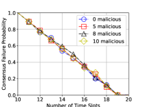
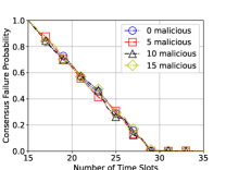
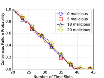
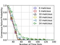
Lastly, we study the number of time slots required by PoP to reach consensus in 2LDAG when malicious nodes exist. Each node generates one block per one or two time slots. We evaluate the consensus failure probability when 2LDAG verifies a block generated in the first time slots. We say a consensus reaches when the consensus failure probability is zero. We consider four scenarios where in Fig. 9. Note, for a network with 50 nodes, it can only tolerate up to 24 malicious nodes. From Fig. 9, the number of time slots to reach consensus increases with . This is because PoP requires a longer path. Moreover, the number of malicious nodes does not have a significant influence on the consensus time for the following values: . However, consensus takes up to 120 time slots when . This is because a validator must find a path that contains all honest nodes to verify a block.
VII Conclusions
This paper presents a novel 2LDAG architecture based on DAG and a PoP protocol to ensure IoT data integrity. 2LDAG has lower storage and communication costs as compared to solutions that leverage PBFT and DAG blockchains. Hence, it is highly suited for use by IoT networks with resource constrained nodes. Moreover, 2LDAG has a high throughput. This is because all nodes are able to generate data blocks and transmit hashes independently. Further, the block generation rate of nodes is not limited by a consensus process. The simulation results show that 2LDAG reduces the storage cost by two orders of magnitude, and the communication cost by three orders of magnitude than PBFT and IOTA blockchains. A potential future of 2LDAG is to construct the shortest path from a validator to a verifier in the physical layer when running the PoP protocol. This further reduces communication overhead for transmitting data block headers. Another future work is dynamic scenarios whereby nodes join and leave a network over time.
References
- [1] L.-H. Lee, T. Braud, P. Zhou, L. Wang, D. Xu, Z. Lin, A. Kumar, C. Bermejo, and P. Hui, “All one needs to know about metaverse: A complete survey on technological singularity, virtual ecosystem, and research agenda,” ArXiv, vol. abs/2110.05352, 2021.
- [2] G. Coorey, G. A. Figtree, D. F. Fletcher, and J. Redfern, “The health digital twin: advancing precision cardiovascular medicine,” Nature Reviews Cardiology, vol. 18, no. 12, pp. 803–804, 2021.
- [3] I. Yaqoob, K. Salah, M. Uddin, R. Jayaraman, M. Omar, and M. Imran, “Blockchain for digital twins: Recent advances and future research challenges,” IEEE Network, vol. 34, pp. 290–298, Sept. 2020.
- [4] S. Suhail, R. Hussain, R. Jurdak, A. Oracevic, K. Salah, C. S. Hong, and R. Matulevičius, “Blockchain-based digital twins: Research trends, issues, and future challenges,” ACM Comput. Surv., vol. 54, sep 2022.
- [5] A. Sharma, E. S. Pilli, A. P. Mazumdar, and P. Gera, “Towards trustworthy internet of things: A survey on trust management applications and schemes,” Computer Communications, vol. 160, pp. 475–493, 2020.
- [6] S. Malik, V. Dedeoglu, S. S. Kanhere, and R. Jurdak, “Trustchain: Trust management in blockchain and IoT supported supply chains,” in IEEE International Conference on Blockchain (Blockchain), (Seoul, South Korea), pp. 184–193, May 2019.
- [7] Q. Zhou, H. Huang, Z. Zheng, and J. Bian, “Solutions to scalability of blockchain: A survey,” IEEE Access, vol. 8, pp. 16440–16455, 2020.
- [8] “Bitcoin size.” [Online]. Available: https://ycharts.com/indicators/bitcoin_blockchain_size.
- [9] X. Ledger, “Capacity planning,” 2022. [Online]. Available: https://xrpl.org/capacity-planning.html.
- [10] L. M. Bach, B. Mihaljevic, and M. Zagar, “Comparative analysis of blockchain consensus algorithms,” in Proceedings of the 41st International Convention on Information and Communication Technology, Electronics and Microelectronics, (Opatija, Croatia), pp. 1545–1550, 2018.
- [11] BitcoinCore, “Running a full node,” 2022. [Online]. Available: https://bitcoin.org/en/full-node.
- [12] M. N. Aman, B. Sikdar, K. C. Chua, and A. Ali, “Low power data integrity in IoT systems,” IEEE Internet of Things Journal, vol. 5, pp. 3102–3113, Apr. 2018.
- [13] C. Doukas, I. Maglogiannis, V. Koufi, F. Malamateniou, and G. Vassilacopoulos, “Enabling data protection through pki encryption in iot m-health devices,” in IEEE 12th International Conference on Bioinformatics and Bioengineering (BIBE), (Larnaca, Cyprus), pp. 25–29, Nov. 2012.
- [14] S. Nakamoto, “Bitcoin: A peer-to-peer electronic cash system,” 2008. [Online]. Available: https://bitcoin.org/bitcoin.pdf.
- [15] M. Yu, S. Sahraei, S. Li, S. Avestimehr, S. Kannan, and P. Viswanath, “Coded merkle tree: Solving data availability attacks in blockchains,” in International Conference on Financial Cryptography and Data Security, (Kota Kinabalu, Malaysia), pp. 114–134, Springer, Feb. 2020.
- [16] G. Wang, Z. J. Shi, M. Nixon, and S. Han, “Sok: Sharding on blockchain,” in Proceedings of the 1st ACM Conference on Advances in Financial Technologies, pp. 41–61, 2019.
- [17] C. Yang, K.-W. Chin, J. Wang, X. Wang, Y. Liu, and Z. Zheng, “Scaling blockchains with error correction codes: A survey on coded blockchains,” arXiv preprint arXiv:2208.09255, 2022.
- [18] Q. Wang, J. Yu, S. Chen, and Y. Xiang, “Sok: Diving into DAG-based blockchain systems,” arXiv preprint arXiv:2012.06128v2, 2020.
- [19] S. Popov, “The tangle,” 2018. [Online]. Available: https://assets.ctfassets.net/r1dr6vzfxhev/2t4uxvsIqk0EUau6g2sw0g/45eae33637ca92f85dd9f4a3a218e1ec/iota1_4_3.pdf.
- [20] M. S. Ferdous, M. J. M. Chowdhury, M. A. Hoque, and A. Colman, “Blockchain consensus algorithms: A survey,” arXiv preprint arXiv:2001.07091, 2020.
- [21] M. Salimitari, M. Chatterjee, and Y. P. Fallah, “A survey on consensus methods in blockchain for resource-constrained IoT networks,” Elsevier Internet of Things, vol. 11, p. 100212, 2020.
- [22] M. Bowman, D. Das, A. Mandal, and H. Montgomery, “On elapsed time consensus protocols,” in International Conference on Cryptology in India, pp. 559–583, Dec. 2021.
- [23] A. Miller, Y. Xia, K. Croman, E. Shi, and D. Song, “The honey badger of BFT protocols,” in ACM SIGSAC conference on computer and communications security, (Vienna, Austria), pp. 31–42, Oct. 2016.
- [24] S. Al Salami, J. Baek, K. Salah, and E. Damiani, “Lightweight encryption for smart home,” in 11th International Conference on Availability, Reliability and Security (ARES), (Salzburg, Austria), pp. 382–388, Aug. 2016.
- [25] I. Butun, P. Österberg, and H. Song, “Security of the internet of things: Vulnerabilities, attacks, and countermeasures,” IEEE Communications Surveys and Tutorials, vol. 22, no. 1, pp. 616–644, 2020.
- [26] G. Han, J. Jiang, L. Shu, J. Niu, and H. Chao, “Management and applications of trust in wireless sensor networks: A survey,” Journal of Computer and System Sciences, vol. 80, no. 3, pp. 602–617, 2014.
- [27] A. Perrig, R. Szewczyk, J. D. Tygar, V. Wen, and D. E. Culler, “SPINS: Security protocols for sensor networks,” Springer Wireless Networks, vol. 8, pp. 521–534, 2002.
- [28] C. Karlof and D. Wagner, “Secure routing in wireless sensor networks: Attacks and countermeasures,” Elsevier Ad-Hoc Networks, vol. 1, p. 293=315, 2003.
- [29] M. Castro, B. Liskov, et al., “Practical byzantine fault tolerance,” in USENIX OSDI, vol. 99, (New Orleans, Louisiana, USA), pp. 173–186, 1999.