Learning to Detect Touches on Cluttered Tables
Abstract
We present a novel self-contained camera-projector tabletop system with a lamp form-factor that brings digital intelligence to our tables. We propose a real-time, on-device, learning-based touch detection algorithm that makes any tabletop interactive. The top-down configuration and learning-based algorithm makes our method robust to the presence of clutter, a main limitation of existing camera-projector tabletop systems. Our research prototype enables a set of experiences that combine hand interactions and objects present on the table. A video can be found at https://youtu.be/hElC_c25Fg8.
1 Introduction
Interactive tabletop projectors are gaining attention, with many commercial and research prototypes being developed [29, 33, 4, 22]. To provide a natural input mechanism, many of these tabletop projectors emulate a touchscreen by recognizing when human fingers contact the table surface. The most common approach commercial devices follow is to project a sheet of infrared light just above the surface while watching for fingertips to intercept the light from just above. For example, the Canesta device [24] is one of the first commercial devices to implement this approach.
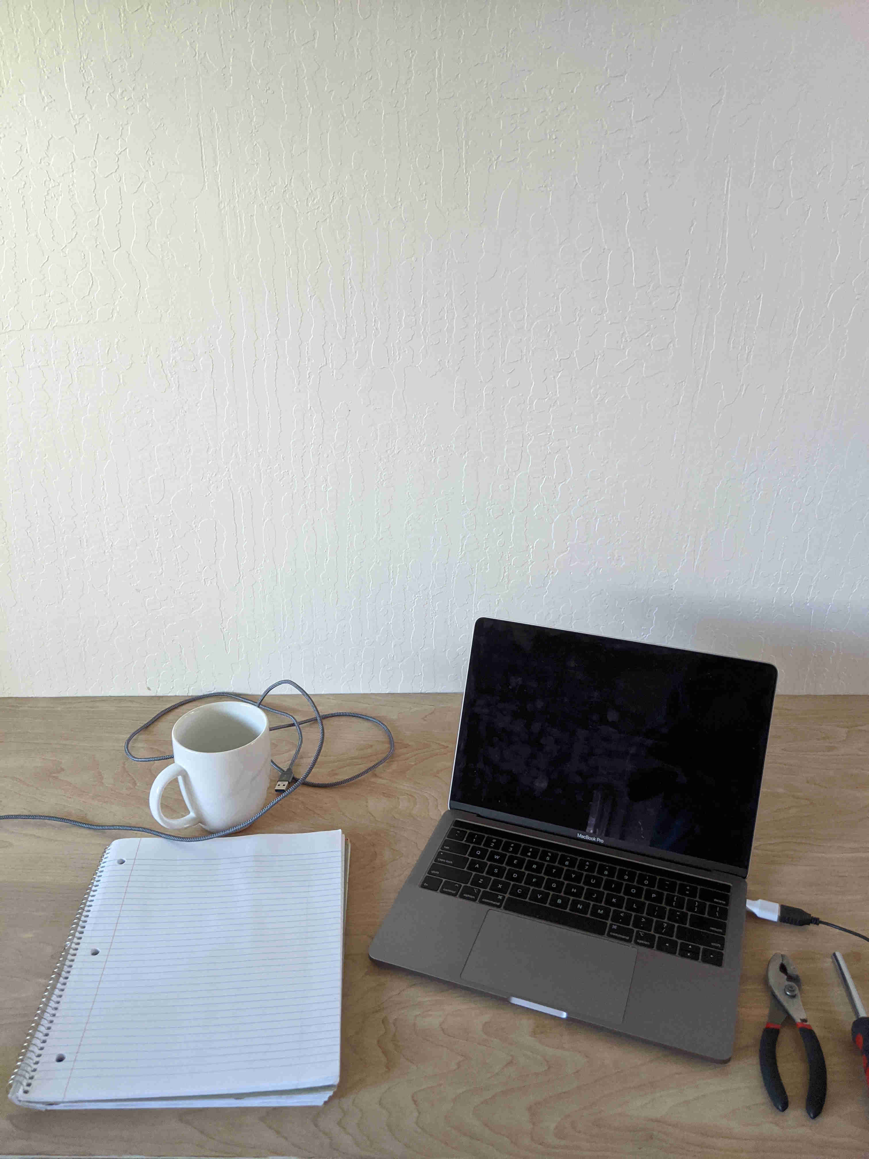
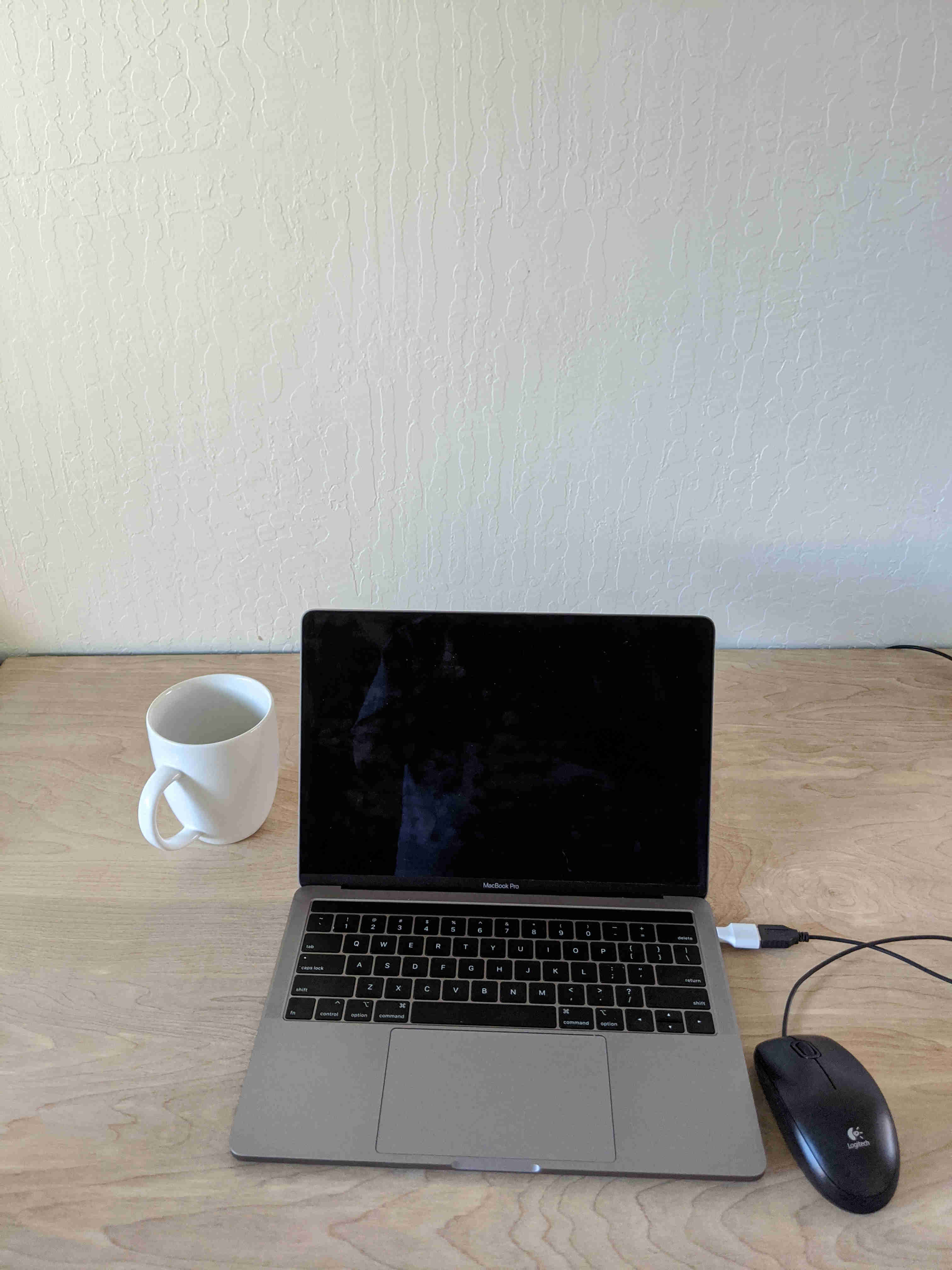
To extend the interactions supported by these systems, several computer vision based approaches have been proposed [29, 30, 16, 33]. These touch systems require the table surface to be mostly empty, which is not a common case. Therefore, the adoption of interactive tabletop projectors has been limited due to their inability to address challenges posed by the presence of clutter on a tabletop. Figure 1 illustrates a typical tabletop set up. In addition, these systems generally require expensive sensors or desktop machines with high-end GPUs and CPUs. Thus, these approaches are impractical for commercial devices that need to be robust to clutter on the table, portable, self-contained, low-cost, and have limited computational resources.
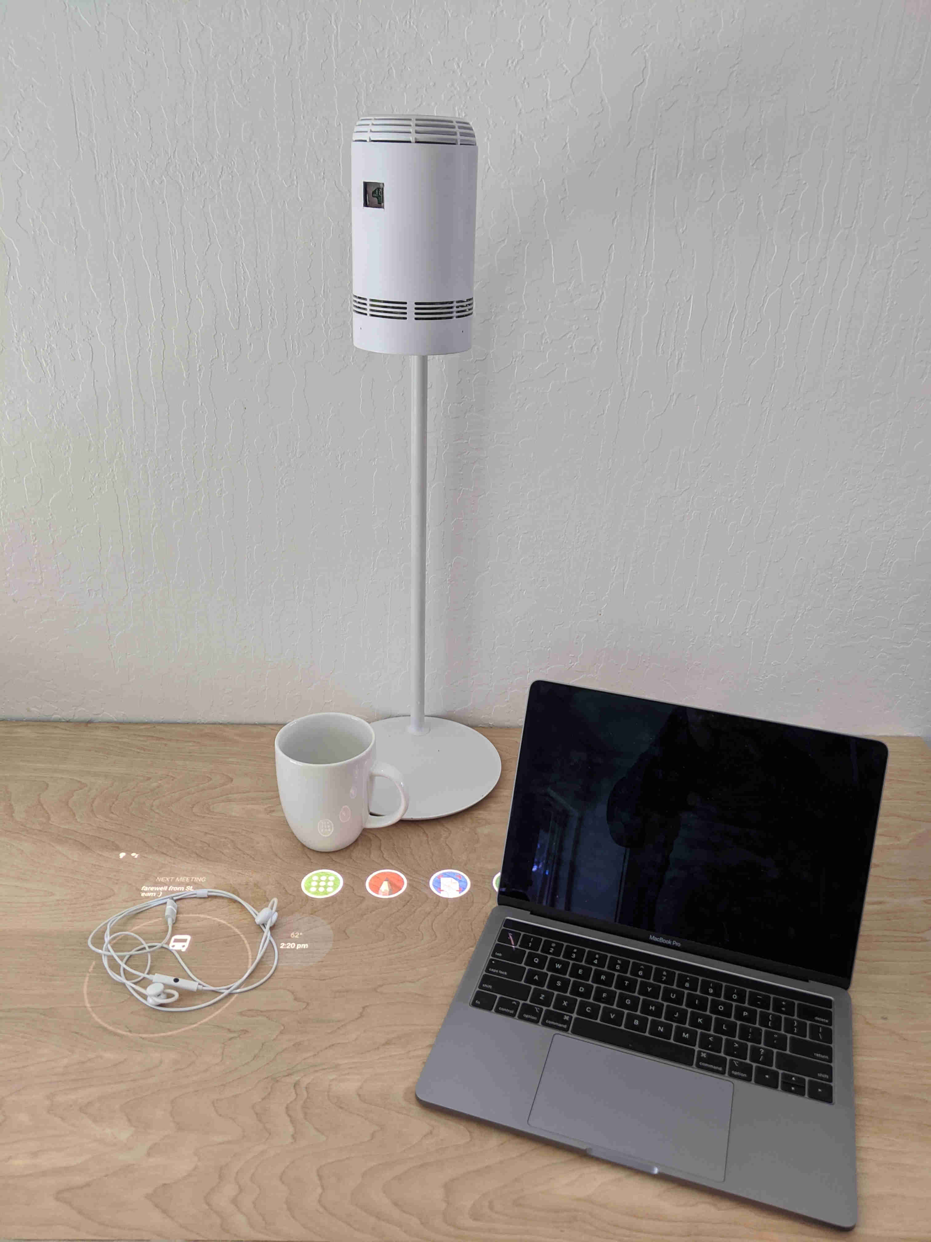
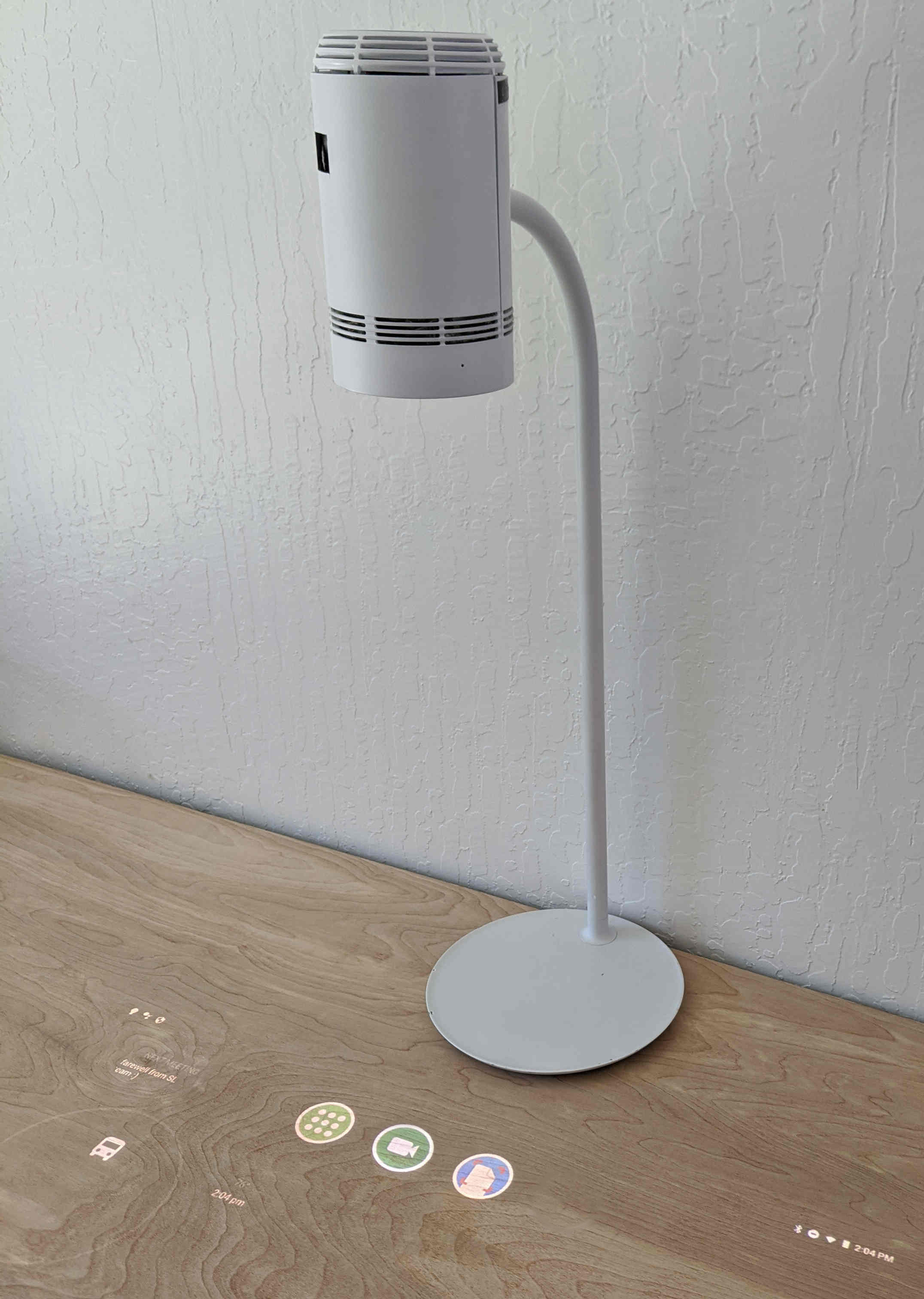
In this paper we present a novel, low-cost, portable, and self-contained tabletop projector prototype that has a lamp form factor (see Figure 2). To interact with the system we propose a novel real-time vision-based algorithm that is based on encoding-decoding networks with skip connections [19, 12, 17]. Our algorithm uses stereo infrared cameras to detect touches and in-air hand gestures. The overhead cameras in the lamp make our prototype less prone to occlusions, thereby overcoming an important limitation in most commercial interactive tabletop projectors. By being robust to clutter and occlusion, our system enables us to build interactive tabletop projector experiences on realistic scenarios. To our knowledge, this is the first time an end-to-end learning-based approach has been proposed to detect when a finger is touching the table.
2 Related Work
There is a large body of work on touch detection. The problem has received attention since it has been a key component for interactive-tabletops [33, 30, 29], semi-transparent screens [28], and wearable devices [35, 7].
A wide range of cues have been explored to detect touches on un-instrumented surfaces. Given the difficulty of the problem, initial approaches [26, 28] proposed relying on microphones to detect touches. Later, PlayAnywhere [29] proposed an algorithm based on the analysis of shadows produced by the IR illuminant. PlayAnywhere’s front-facing configuration helps to overcome many occlusion problems, however shadows are not easy to detect on a cluttered table.
Many approaches have been proposed to exploit the geometrical properties that relate stereo cameras. Wren et al [32] proposed a technique based on precomputed disparity maps, which can detect when a fingertip is between an upper and lower plane without computing the entire depth range. TouchLight [28] uses the homography induced by a plane to detect when objects are near a semi-transparent screen. Visual Touchpad [14] detects the fingertips in each camera independently and applies a disparity threshold to decide if the finger is touching the touch-pad. Finally, Agarwal et al [1] proposed an algorithm that aggregates stereo cues from several points at each fingertip by computing the intersection of the finger plane and the screen plane.
Compared with our approach, [32, 14] use very low-resolution images and [1] achieves only 20 fps. Most of the approaches mentioned above are generally divided in two stages, first they detect the fingertip and then they use a heuristic based on the stereo images to decide if the fingertip is touching the surface. Our end-to-end learning-based approach finds the fingertip position and decides if the fingertip is touching the table in a single step. Our novel method runs at 30 fps, is very accurate, and leverages the geometrical properties of stereo cameras.
A recent trend is to leverage depth sensors to detect touches. Wilson et al. [30] explores a method to detect touches in which a static background model is computed during initialization. Posterior depth images are processed to identify areas with pixels that have a depth value similar to the static background model. Murugappan et al. [16] proposes to further refine the conditions to detect touches in [30] by using connected component analysis to discard blobs based on their area. Additionally, a novel method for touch-gesture detection is proposed. Xiao et al. [33] combines depth and infrared streams to obtain precise finger boundaries, then examines a small depth pixel neighborhood around the fingertip to decide if it is touching the table. Their method has a fallback mode that allows them to cope with limited clutter conditions. Cadena et al. [2] detects the arms using k-means and, then finds the fingertips and refines their position using IR edge detection. OmniTouch [7] finds fingers by searching for cylinders in the depth image and performing flood filling to detect if it is touching a surface. Desktopography [34] adds additional constraints to [7] to reject finger-like objects. Chai et al. [4] follows [30] but the fingertips are found using a neural network. Fujinawa et al. [6] proposes a system in which interactions are driven by hand postures. The closest approaches to our work use neural networks to detect fingertips or analyze hand pose [6, 4]. The main difference to our approach is that they rely on heuristics based on depth signals to decide if a fingertip is touching the table.
A common limitation of these approaches is that they are not very precise in disambiguating hover from touch. The main issue is that there are assumptions about finger thickness. This assumption can be easily violated depending on the angle the finger touches the surface. Additionally, finger thicknesses vary depending on the user. In contrast, our approach can learn how to handle these situations from the data. By using stereo pair images, our neural network can pick additional cues other than just the ones provided by the depth information. Finally, it is important to note that even when depth sensors have become widely available and they are not very expensive, they are significantly more expensive than the stereo camera pair we use.
3 Configuration
Figure 2 shows our lamp prototype which has two parts, a smart headlamp attached to a normal lamp base. The prototype is designed to sit on a flat surface such as a table or desk. The head is 48 cm above the surface and contains a vision module, projector and the main system board where all the computing happens. Apart from the power cable connected to the base, there are no other cables or hardware required to use the lamp.
The vision module has two 1 MP infrared cameras (OV9282), with a 5cm baseline, one infrared flood illuminator, and one 13MP RGB camera. Similar to other camera-projector systems [29] we remove the projected graphics from the infrared images using an infrared band-pass filter mounted in front of the infrared cameras. In addition, we use BELICE dot emitters to add texture to the scene to facilitate finding correspondences between the infrared cameras. The vision module is similar to the one in the RealSense 435, but has a lower cost since we do not need a dedicated ASIC to compute depth.
Our system has a projector based on the TI DLP4500/6401. The projector has a 1280x800 resolution and at 48cm over the surface has 71cm diagonal. The main board has a Qualcomm 605 System-on-Chip (SoC), which supports up to three cameras and can execute neural network inference on a built-in hardware accelerator (Hexagon 685 DSP). The Qualcomm 605 processing capabilities are similar to the ones of a Google Pixel 2. The prototype runs Android Oreo and all the hand-user interaction events are recognized and dispatched to the OS as if they were coming from an input device. The total cost of the device is below the price of most smartphones.
4 Stereo Hand interaction
The stereo hand interaction module processes the frames from the two infrared cameras to detect touches and in-air hand gestures. We use a two step process to detect touches, first we detect the hands on the images from left camera, then for each detected hand we use the stereo image pair to determine both the fingertip locations and the subset that are touching the tabletop.
4.1 Calibration and Table model
We perform a one-time calibration that estimates the intrinsic and extrinsic parameters for all the cameras in the device, using a chessboard target and the method described in [36]. Then, we find the mapping between the projector and the RGB camera by projecting a sequence of gray code patterns onto the table [15].
Our touch detection algorithm requires highly accurate estimation of the distance between the infrared cameras and the surface the user interacts with. A common solution when using depth sensors is to clear the surface and build a static histogram using the first frames of the depth sensor [4, 30]. Since requesting the user to empty the table can be cumbersome, some methods maintain a rolling window of the depth data [6, 33].
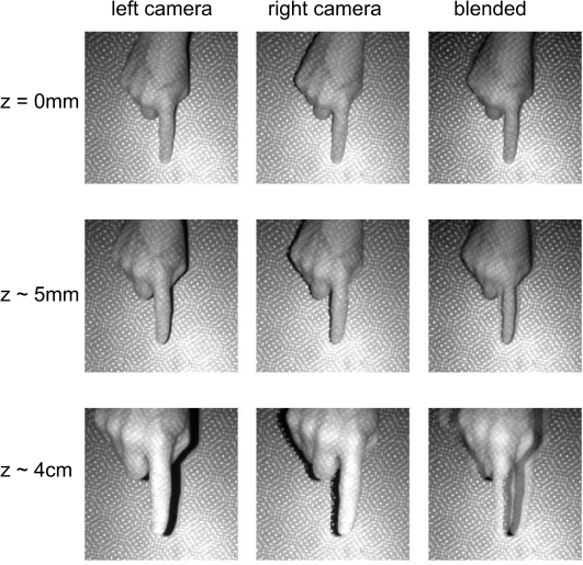
However, we do not compute a depth map and instead infer the surface plane even through clutter, following a similar process to [28, 1, 5]. We capture the chessboard calibration pattern when it is lying flat on the table and use all chessboard calibration corners to estimate the homography relating the undistorted infrared images. Finally, we compute disparity maps that maps points on the plane of the table from the left camera to the right camera. Figure 3 illustrates the image before and after the homography is applied.
4.2 Hands Detection
The first step in our hand interaction algorithm is to detect hands in re-scaled frames from the left camera , where is the width of the image, is the height, and is the re-scale factor. Since the purpose of this step is to be able to obtain a rough estimate of the hands position in the scene we heavily reduce the resolution of the left image in this step using .
Following [37], our neural network predicts a bounding box for each hand. Let be the coordinates of the hand bounding box corners. The center of the bounding box is given by , and the size of the bounding box is .
Our neural network estimates , where is the output stride. The heatmap predicts the center of the bounding box. When the neural network is predicting a bounding box with center and when it is predicting that there is no bounding box. During training, for each low resolution bounding box center , we create the corresponding heatmap using a Gaussian kernel , where depends on the size of the bounding box [25] and is a constant to normalize the heatmap. We define the loss for the center of the bounding box as:
| (1) |
where and are hyper-parameters of the focal-loss [13] and is the number of hands in the image.
In addition, our neural network estimates . We use to regress the size of the bounding box, the value at the center of the is the predicted size of the bounding box. We define the loss for the size as:
| (2) |
The overall training objective is for the network is:
| (3) |
where is used to change the importance in the overall training objective. In our experiments we fix .
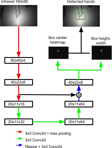
The neural network architecture is shown in Figure 4. This is a fully convolutional neural network in which all layers are followed by a batch normalization operation [9] and a ReLU non-linearity (except for the last one) and has an encoder-decoder architecture with skip connections[19, 12, 17]. Fast inference is central to our design and we have found that our model is robust to many design choices. We experimented with more sophisticated blocks [8] and observed minimal improvements.
The encoding layers of the network interleaves convolutional layers (with point-wise non-linearities) and max-pooling layers to compute semantically meaningful features. The pooling layers reduce the spatial resolution of the features and introduce invariance to small spatial deformations. The decoding layers of the network increase the feature resolution, using bi-linear up-sampling and convolution layers [31]. The resulting features are combined with features from the encoding layers via skip connections. We decided to use these operations since they can be hardware accelerated. The output heatmaps and share the same encoder-decoder network. To produce each output heatmaps, the features of the encoder-decoder network are passed through a separate convolution.
We use random flips, rotations, brightness changes, and contrast adjustment to augment our training set. We use Adam [11] and set the learning rate to to optimize the overall objective from scratch.
4.3 Touch Detection
Deep neural network techniques to estimate hand pose [25] and person pose [17] have gained popularity due to the impressive performance they have shown. RGB [38, 3] and depth [25] are the most common input modalities. The number of joints to represent hand pose vary depending on the datasets that are used for evaluation; [25] uses 14 joints, [23] uses 16 joints, and [20] uses 21 joints. The predicted joints are either represented using heatmaps or using their 2D coordinates.
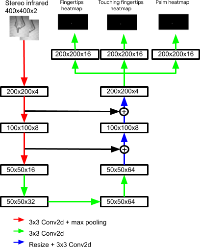
In our system, instead of predicting the full hand pose we train a neural network that only predicts the position of the fingertips and the palm , which are the only keypoints that we need. Our neural network estimates three heatmaps: encodes the position of all the fingertips in the hand, encodes which fingertips are touching the table, and encodes the position of the palm, where is the output stride for the neural network.
During training, we remap the using linear interpolation:
| (4) |
We feed and to our neural network. As in the previous section, we use Gaussian kernels to create the heatmaps. For the fingertips heatmap we use only one heatmap to encode the position of all the fingertips since we are not interested in which specific finger is touching:
| (5) |
where is a normalizing constant and is a fixed parameter for all keypoints. We create the touching heatmap in the same way we create the fingertips heatmap but we only consider the fingertips that are touching the table. If a keypoint is not visible we ignore it when we create the heatmaps. We use the Mean Square Error (MSE) loss [25, 17] to compare the predicted heatmaps with the ground-truth as training objective:
| (6) |
During inference, for each detected hand bounding box , we crop the left image and use the disparity maps to remap the corresponding bounding box in the right image . We feed and images to our neural network. Then, we decode the fingertip positions by finding the local maximas (and using non-maximal suppression) in . Once we have the local maxima coordinates we fit a 2D Gaussian function to obtain the coordinates with sub-pixel precision. To decide if a fingertip is touching the table, we take the maximum value of in a window centered around the fingertip position .
Figure 5 shows the neural network architecture for this stage, which is similar to the neural network to detect hands but with more decoding layers. The additional decoding layers enable us to obtain spatially accurate positions for the predicted keypoints. It is important to note that, since our neural network is fully convolutional, the image sizes that we use to train the network do not need to be the same as the ones that we use when we run inference. We train using full stereo images but we feed cropped stereo images during inference.
The main reason our neural network can estimate is that it can exploit geometrical constraints and other cues. A fingertip touching the table should have a similar position in and . The further away a fingertip is from the table, the further apart its position is in and . Figure 3 illustrates this property. By using a learning-based approach that recognizes when a finger is touching the table, we are able to successfully handle many cases that were found to be difficult in previous heuristic-based approaches [35, 4]. For example, when a finger is touching the table perpendicularly, heuristics that use connected components struggle to detect touches because the connected component that the finger creates is small. However, our system easily handles this case.
4.4 Touch Dataset
To train the touch detection CNN we need a dataset with accurate labels of when the fingertips are touching the table. The main challenge is that annotating whether a fingertip is touching the table using stereo images is time consuming and error prone. Therefore, when we collected the dataset we requested the participants to perform tasks in which we knew which fingers were touching the table and which fingers were hovering over the table.
We collected 50 thousand stereo image pairs from 13 volunteers and 3 different devices. Each volunteer was requested to perform 14 tasks for 20 seconds each. The tasks consisted of moving one hand around the projected area while performing a gesture with a pre-determined subset of fingers from that hand. For example, some of the gestures were: touch while pinching with the thumb and index finger, touch while performing two finger scroll, and move the hand above the table without touching it. Also, we requested the participants to hover their hand above the table but without touching it, while performing similar gestures, in order to obtain samples that can help us learn an accurate touch detector. We tried to emulate realistic tabletop scenarios by introducing a variety of clutter into the scene. Between different tasks, we modified the scene by adding or removing objects, as well as changing the illumination or the surface material. After collecting the stereo images we annotated the keypoint locations on the left image.
4.5 Multi-Touch Tracking
Our system can detect up to two hands and ten contact points simultaneously. Given two consecutive frames at time and , and the detected contact points set and in each frame, we match the contact points to if the following two conditions hold simultaneously:
| (7) |
| (8) |
When this happens, we report a drag event if the mm. When a contact point does not match to any contact point in , we report the contact point as a touch down event to the Android OS. Similarly, when a contact point does not match to any contact point in nor we report a touch up event. By reporting events to the Android OS, and keeping a stable fingertip identity among frames, many of the Android gestures (one or two finger drag, long press, pinch-zoom, etc…) work well, allowing us to use most Android applications without modifications.
4.6 In-Air Hand Gesture Detection
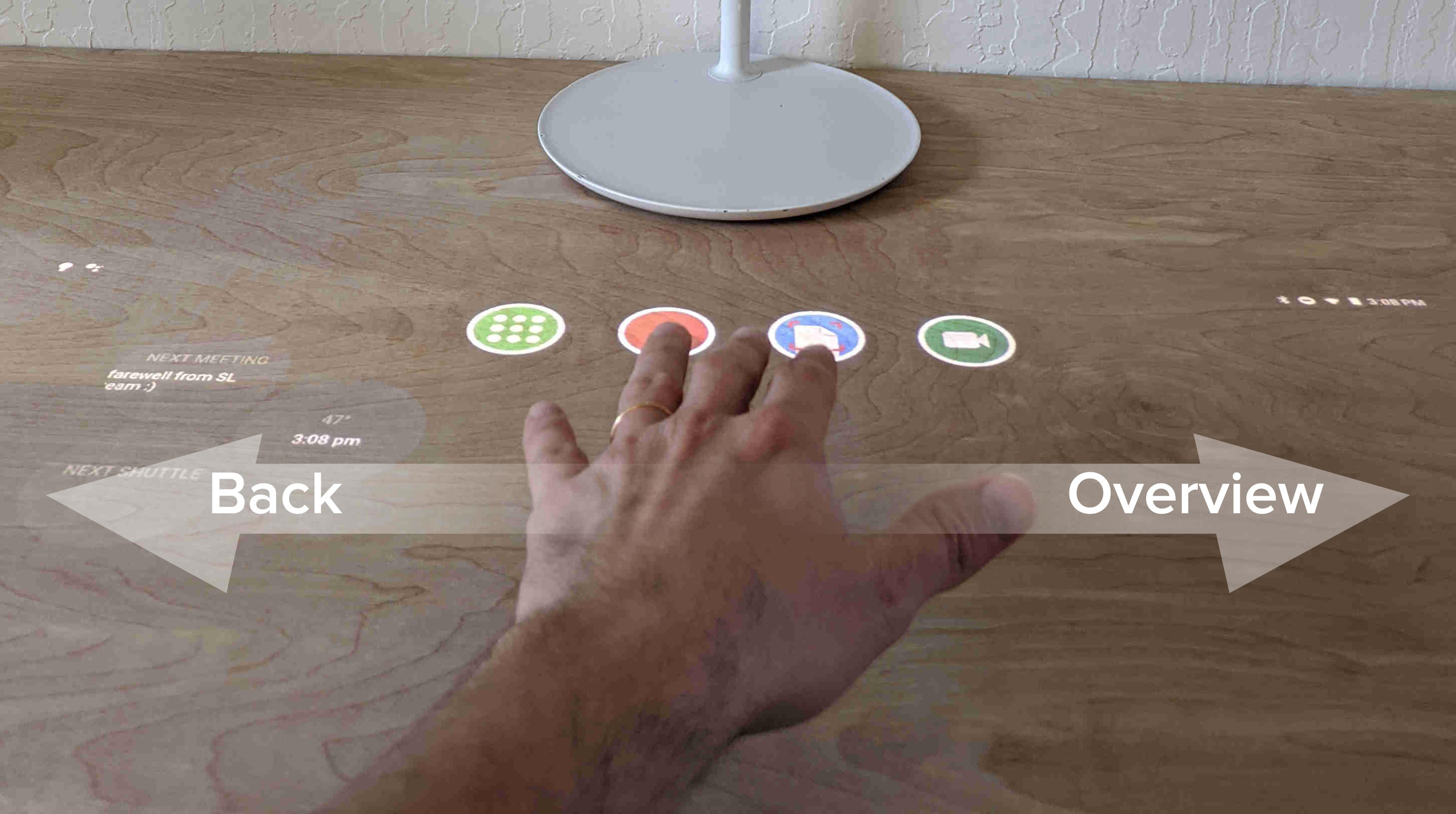
We use in-air gestures to replace the Android navigation bar. Our system detects two in-air gestures: back and forward, as depicted in Figure 6. The gestures are mapped to the back and overview buttons in the Android navigation bar. In order to detect in-air gestures we implemented heuristics based on speed and directionality of the user’s hand motion.
5 Implementation Details
The CNNs in the system are run on Qualcomm’s DSP using TF-Lite’s hexagon delegate and are trained using quantization-aware training [10]. The neural network in the first stage takes 6ms to run and the one in the second stage takes 12ms per hand, we process two hands at most and ignore the rest of the hands in the scene. By offloading inference to Qualcomm’s DSP, and using only one slow SoC core for the touch detection algorithm, we can efficiently distribute the compute workloads on the device. The big cores and most of the small cores on the SoC are reserved for running the Android operating system and applications.
6 Experiments
We conducted experiments with our system through an evaluation of touch accuracy, latency measurements, dealing with failure cases, and informal testing with various experiences.
6.1 Touch Accuracy
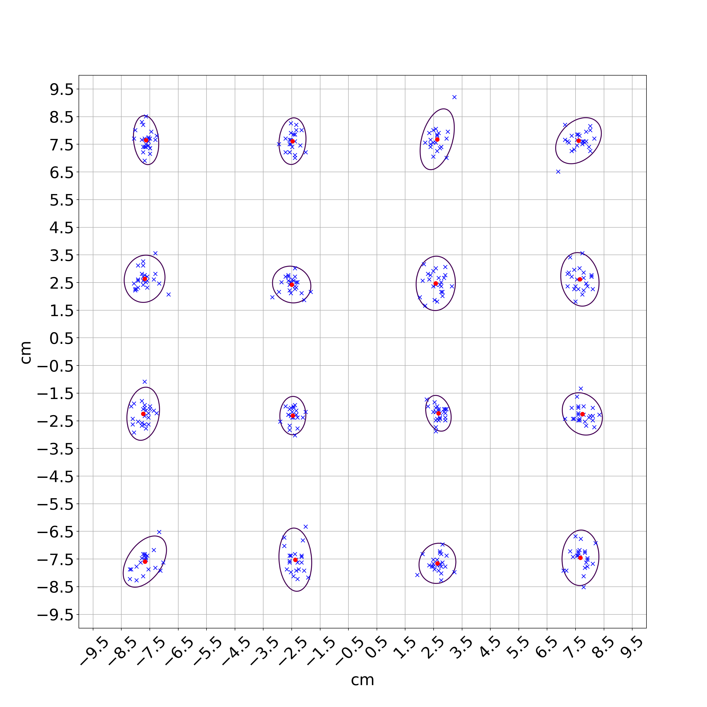
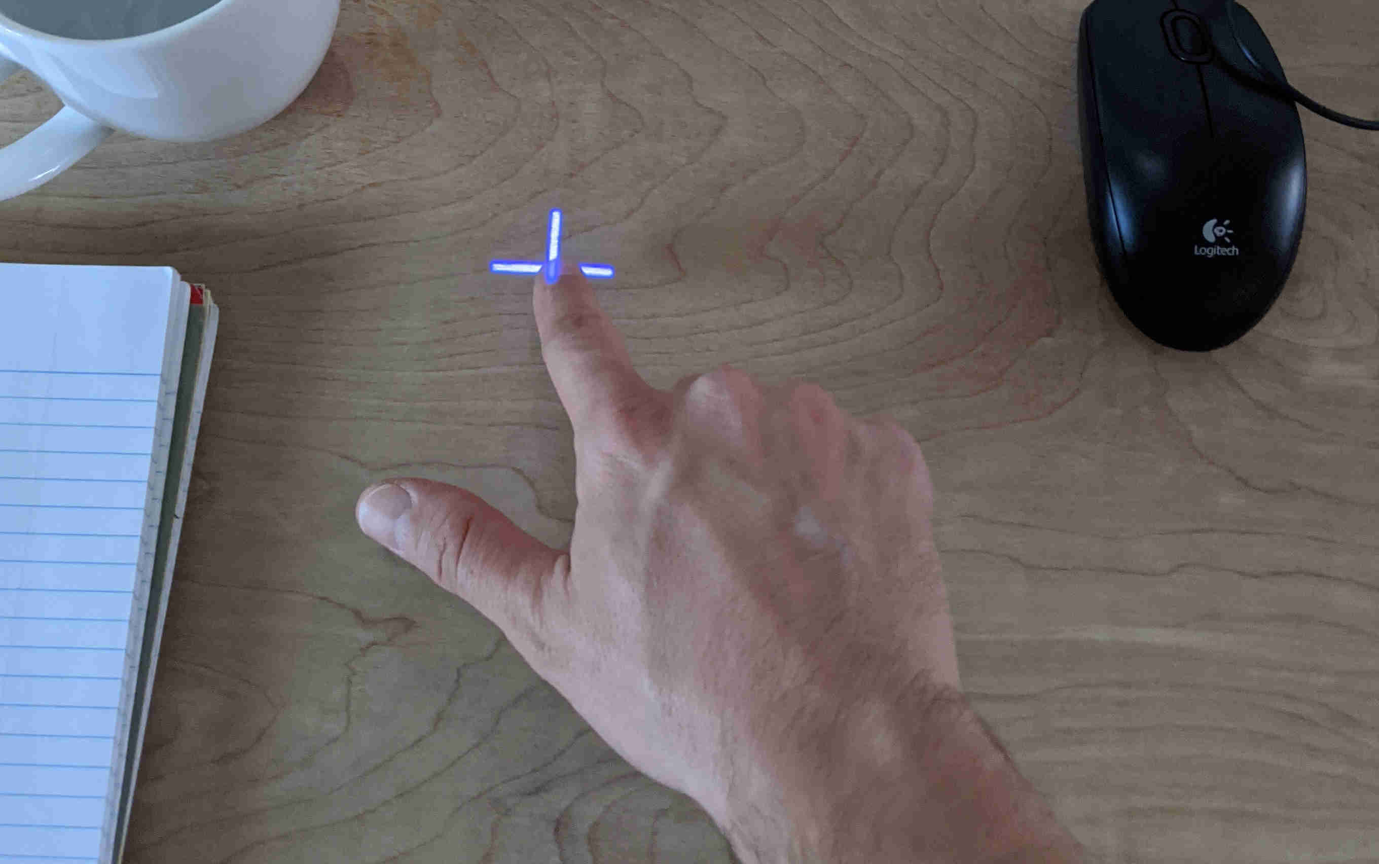
To analyze the spatial and touch accuracy of the system we performed a user study similar to the cross-hair targeting study described in [35]. We requested 12 participants to tap once on the cross-hair targets projected on the table. A total of 16 cross-hair targets were projected. All users were given a training period of 10 minutes.
The targets were placed in a grid evenly spaced across a cm square area. The targets were displayed in random order, one at the time, for three seconds each. The system recorded all the touch events. To capture diversity of interactions, we evaluated under two different scenarios, with the user seated in a chair, and with the user standing. Clutter was present on the table, but not in places where the target was shown (See Figure 8).
Across the 12 participants, we obtained 384 cross-hair trials. Of these, 10 (2.6%) reported no touch contact, 370 (96.35%) exactly one contact and 4 (1.04%) more than one contact. In the event of multiple detected contacts, we decided to ignore the trial for the rest of the analysis. We found no significant spatial or touch accuracy differences between the user in seated or standing position. Figure 7 plots the touch points and the 95% confidence intervals for the seated and standing positions. 98% of touch interactions were detected within 1 cm of the actual target. The average Euclidean error is 0.45cm.
6.2 Comparison with Existing Approaches
| Camera | Sensor | Avg. Euclidean | Touch Detection | Clutter | Hardware | Cost | |
|---|---|---|---|---|---|---|---|
| Distance | Type | Error | Rate | Robustness | |||
| Wilson [30] | 75cm | depth | 7mm | N/A | low | Desktop machine | medium |
| structured-light | CPU | ||||||
| Xiao et al [33] | 160cm | IR+depth | 4.8mm | 99.3% | medium | Desktop machine | medium |
| time-of-flight | CPU | ||||||
| Chai et al [4] | N/A | depth | 2.5mm | N/A | low | Desktop machine | high |
| structured-light | high-end GPU | ||||||
| Xiao et al [35] | 51cm | IR+depth | 5mm | 72% | medium | HoloLens | low |
| table condition | time-of-flight | ||||||
| Ours | 48cm | stereo IR | 4.9mm | 96.35% | high | Qualcomm | low |
| structured-light | 605 SoC |
There are many touch detection algorithms that have been proposed in the past. Table 1 shows a comparison between our approach and closest previous systems. We compare with approaches in which the setup is similar to our top-view interactive tabletop projector system. There is a wide variety of setups, costs, camera distances, and results. Our approach achieves the best touch detection rate of the low cost systems and it is the most robust to clutter.
To obtain a rough cost estimate for each approach we considered that desktop machines are more expensive than embedded devices and that high-end GPUs are extremely expensive. Time-of-flight depth sensors are more expensive than structured-light depth sensors. Stereo infrared cameras with structured-light are the cheapest alternative.
To analyze the clutter robustness of each system we considered whether the method supports dynamic backgrounds and, if it does, how complex the scene can be. For example, [33, 35] have problems to detect touches in the presence of documents like the one in Figure 11 since it is very likely that an overfill error gets triggered.
6.3 Latency
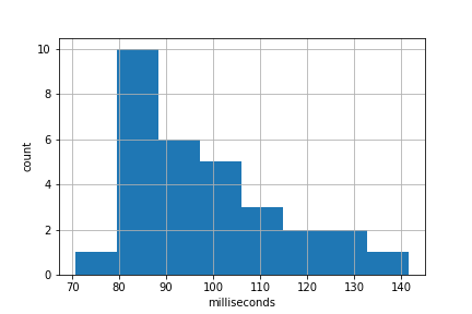
We measured the end-to-end latency of the system, defined as the time between the physical interaction and the first frame that incorporates it. This measurement includes the time required to capture the frames, process them and dispatch the OS event.
To measure the end-to-end latency of the system, we positioned a high-speed camera near lamp base and we recorded 30 tap interactions with our system. Figure 9 shows the latency distribution of the system. We observed a mean latency of our touch system of ms and a mode of ms. Out of these 98 ms, 31 ms are spent in the touch system. The remaining 67 ms are spent in the rest of pipeline and there are many opportunities for optimizing it.
As mentioned in [35] latency is crucial for touch inputs and is more easily noticed in large displays because users can move their hands faster. Our latency compares favorably to the 180 ms latency reported by [35] and even some touchscreen latencies, which are in the (50-200ms) range [18].
6.4 Failure Cases
We evaluated our system on a comprehensive set of use-cases. While we have significantly improved upon the existing use-cases, our system still fails in a few edge cases. One such example is objects resembling a finger can occasionally trigger false positives. We could in the future augment the models with RGB images (in addition to infrared) to help disambiguate these cases. Another failure case is miss-detection when user touches are at the edge of camera’s field of view. The main reason is that the hand is only partially visible in the infrared cameras. This could be mitigated by using a camera with a field of view that is wider than area of interest on a tabletop.
6.5 Sandbox
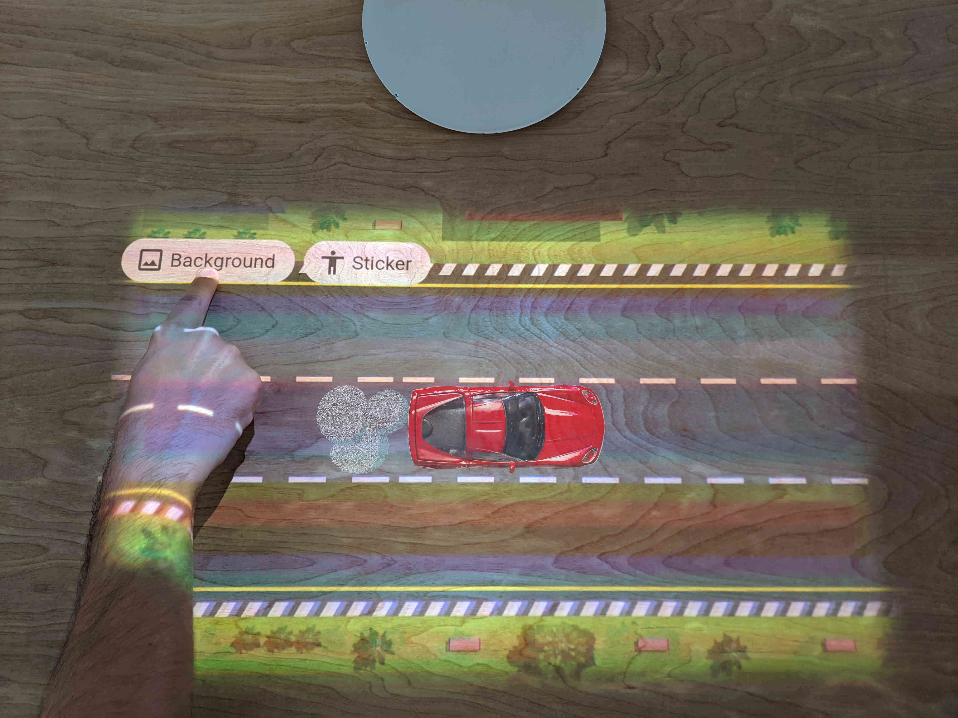
We developed a demo application, Sandbox, that allows the user to choose from different dynamic backgrounds that are projected on toys to augment them with animations, see Figure 10. The toys can be moved through the projected area and animation will track them. The example shows a moving animated race track background, giving the illusion that the toy car is moving. The background can react to the position of the detected toy cars and present different obstacles, turning the table into a race game with real toys. In this example, we also project animated smoke behind the car, amplifying the illusion of movement.
In order to detect when a new toy is present, the Sandbox application detects when the user’s hand enters or leaves the projected area. By comparing the frames associated to those events, we determine if a new object has been placed on the table. We then use the frame the toy is detected in as a reference to track it in following frames using optical flow.
6.6 Desktop
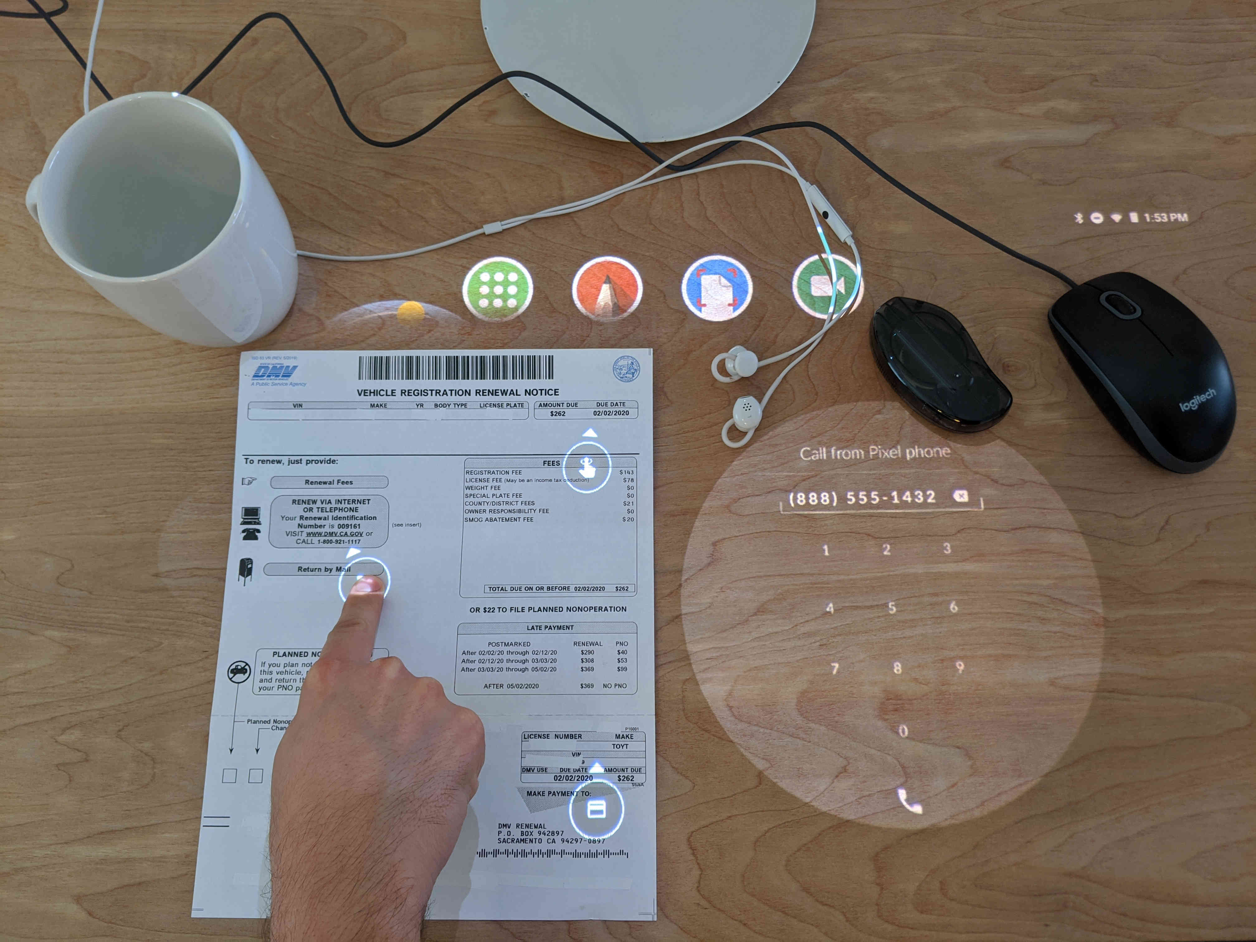
In this demo application we explore interactions with paper documents that are on the table. In the past, many systems have explored these type of interactions, for example Digital Desk [27] and Live Paper [21], project information onto physical objects. In our application, we assume that we know the structure of the document and we attach a user interface to it, making the document interactive. The buttons allow the user to act on the information presented by the document when they are touched. For example, tapping a phone number could trigger the device to call the number. Tapping on the money due could trigger the device to pay the bill. By tracking the document, using optical flow, the user can move it through the table and have the illusion that the graphical user interface is attached to the document. See Figure 11 for an example of a document that we can detect, track, and project a graphical user interface on.
7 Conclusions
In this paper we introduced a new interactive projector-camera prototype with a lamp form factor. The prototype has a novel real-time algorithm that can detect touches and in-air hand gestures. The low-cost prototype uses a middle-tier SoC that is similar to a Google Pixel 2 smartphone and has a vision module that is similar to the RealSense D435. The novel real-time algorithm leverages the hardware acceleration SoC capabilities, that are present in many smartphones. The low-cost prototype is robust to clutter which are important limiting factors for the adoption of interactive tabletop projectors. We showed how the novel prototype enables rich experiences in which the user can interact with the tabletop and objects of interests in realistic tabletop scenarios.
8 Acknowledgements
We would like to thank Rahul Sukthankar and Jay Yagnik for their support and advice. We would also like to thank John Fitch, Eric Cuong Nguyen, Kai Yick, and Mark Zarich for their assistance with hardware prototyping.
References
- [1] Agarwal, A., Izadi, S., Chandraker, M., and Blake, A. High precision multi-touch sensing on surfaces using overhead cameras. In Second Annual IEEE International Workshop on Horizontal Interactive Human-Computer Systems (TABLETOP’07) (2007), IEEE, pp. 197–200.
- [2] Cadena, A., Carvajal, R., Guamán, B., Granda, R., Peláez, E., and Chiluiza, K. Fingertip detection approach on depth image sequences for interactive projection system. In 2016 IEEE Ecuador Technical Chapters Meeting (ETCM) (2016), IEEE, pp. 1–6.
- [3] Cai, Y., Ge, L., Cai, J., and Yuan, J. Weakly-supervised 3d hand pose estimation from monocular RGB images. In Proceedings of the European Conference on Computer Vision (ECCV) (2018), pp. 666–682.
- [4] Chai, Z., and Shilkrot, R. Enhanced touchable projector-depth system with deep hand pose estimation. arXiv preprint arXiv:1812.11090 (2018).
- [5] Chan, L.-W., Kao, H.-S., Chen, M. Y., Lee, M.-S., Hsu, J., and Hung, Y.-P. Touching the void: Direct-touch interaction for intangible displays. In Proceedings of the SIGCHI Conference on Human Factors in Computing Systems (2010), ACM, pp. 2625–2634.
- [6] Fujinawa, E., Goto, K., Irie, A., Wu, S., and Xu, K. Occlusion-aware hand posture based interaction on tabletop projector. In The Adjunct Publication of the 32nd Annual ACM Symposium on User Interface Software and Technology (2019), ACM, pp. 113–115.
- [7] Harrison, C., Benko, H., and Wilson, A. D. OmniTouch: Wearable multitouch interaction everywhere. In Proceedings of the 24th annual ACM symposium on User interface software and technology (2011), pp. 441–450.
- [8] He, K., Zhang, X., Ren, S., and Sun, J. Deep residual learning for image recognition. In Proceedings of the IEEE conference on computer vision and pattern recognition (2016), pp. 770–778.
- [9] Ioffe, S., and Szegedy, C. Batch normalization: Accelerating deep network ttraining by reducing internal covariate shift. arXiv preprint arXiv:1502.03167 (2015).
- [10] Jacob, B., Kligys, S., Chen, B., Zhu, M., Tang, M., Howard, A., Adam, H., and Kalenichenko, D. Quantization and training of neural networks for efficient integer-arithmetic-only inference. In Proceedings of the IEEE Conference on Computer Vision and Pattern Recognition (2018), pp. 2704–2713.
- [11] Kingma, D. P., and Ba, J. Adam: A method for stochastic optimization. arXiv preprint arXiv:1412.6980 (2014).
- [12] Lin, T.-Y., Dollár, P., Girshick, R., He, K., Hariharan, B., and Belongie, S. Feature pyramid networks for object detection. In Proceedings of the IEEE conference on computer vision and pattern recognition (2017), pp. 2117–2125.
- [13] Lin, T.-Y., Goyal, P., Girshick, R., He, K., and Dollár, P. Focal loss for dense object detection. In Proceedings of the IEEE international conference on computer vision (2017), pp. 2980–2988.
- [14] Malik, S., and Laszlo, J. Visual touchpad: A two-handed gestural input device. In Proceedings of the 6th international conference on Multimodal interfaces (2004), pp. 289–296.
- [15] Moreno, D., and Taubin, G. Simple, accurate, and robust projector-camera calibration. In 2012 Second International Conference on 3D Imaging, Modeling, Processing, Visualization & Transmission (2012), IEEE, pp. 464–471.
- [16] Murugappan, S., Elmqvist, N., Ramani, K., et al. Extended multitouch: Recovering touch posture and differentiating users using a depth camera. In Proceedings of the 25th annual ACM symposium on User interface software and technology (2012), ACM, pp. 487–496.
- [17] Newell, A., Yang, K., and Deng, J. Stacked hourglass networks for human pose estimation. In European conference on computer vision (2016), Springer, pp. 483–499.
- [18] Ng, A., Lepinski, J., Wigdor, D., Sanders, S., and Dietz, P. Designing for low-latency direct-touch input. In Proceedings of the 25th annual ACM symposium on User interface software and technology (2012), pp. 453–464.
- [19] Pinheiro, P. O., Lin, T.-Y., Collobert, R., and Dollár, P. Learning to refine object segments. In European Conference on Computer Vision (2016), Springer, pp. 75–91.
- [20] Qian, C., Sun, X., Wei, Y., Tang, X., and Sun, J. Realtime and robust hand tracking from depth. In Proceedings of the IEEE conference on computer vision and pattern recognition (2014), pp. 1106–1113.
- [21] Robertson, C., and Robinson, J. Live paper: video augmentation to simulate interactive paper. In Proceedings of the seventh ACM international conference on Multimedia (Part 2) (1999), pp. 167–170.
- [22] Sony. Sony Xperia Touch. https://www.sonymobile.com/us/products/smart-products/xperia-touch/, 2018. [Online; accessed 19-Dec-2019].
- [23] Tang, D., Jin Chang, H., Tejani, A., and Kim, T.-K. Latent regression forest: Structured estimation of 3d articulated hand posture. In Proceedings of the IEEE conference on computer vision and pattern recognition (2014), pp. 3786–3793.
- [24] Tomasi, C., Rafii, A., and Torunoglu, I. Full-size projection keyboard for handheld devices. Communications of the ACM 46, 7 (2003), 70–75.
- [25] Tompson, J., Stein, M., Lecun, Y., and Perlin, K. Real-time continuous pose recovery of human hands using convolutional networks. ACM Transactions on Graphics (ToG) 33, 5 (2014), 169.
- [26] Wellner, P. The DigitalDesk calculator: Tangible manipulation on a desktop display. In Proceedings of the 4th annual ACM symposium on User interface software and technology (1991), pp. 27–33.
- [27] Wellner, P. Interacting with paper on the digitaldesk. Communications of the ACM 36, 7 (1993), 87–96.
- [28] Wilson, A. D. Touchlight: An imaging touch screen and display for gesture-based interaction. In Proceedings of the 6th international conference on Multimodal interfaces (2004), ACM, pp. 69–76.
- [29] Wilson, A. D. Playanywhere: A compact interactive tabletop projection-vision system. In Proceedings of the 18th annual ACM symposium on User interface software and technology (2005), ACM, pp. 83–92.
- [30] Wilson, A. D. Using a depth camera as a touch sensor. In ACM international conference on interactive tabletops and surfaces (2010), ACM, pp. 69–72.
- [31] Wojna, Z., Uijlings, J. R., Guadarrama, S., Silberman, N., Chen, L.-C., Fathi, A., and Ferrari, V. The devil is in the decoder. In BMVC (2017).
- [32] Wren, C., and Ivanov, Y. Volumetric operations with surface margins. Computer Vision and Pattern Recognition: Technical Sketches (2001).
- [33] Xiao, R., Hudson, S., and Harrison, C. DIRECT: Making touch tracking on ordinary surfaces practical with hybrid depth-infrared sensing. In Proceedings of the 2016 ACM International Conference on Interactive Surfaces and Spaces (2016), ACM, pp. 85–94.
- [34] Xiao, R., Hudson, S., and Harrison, C. Supporting responsive cohabitation between virtual interfaces and physical objects on everyday surfaces. Proceedings of the ACM on Human-Computer Interaction 1, EICS (2017), 1–17.
- [35] Xiao, R., Schwarz, J., Throm, N., Wilson, A. D., and Benko, H. MRTouch: Adding touch input to head-mounted mixed reality. IEEE transactions on visualization and computer graphics 24, 4 (2018), 1653–1660.
- [36] Zhang, Z. A flexible new technique for camera calibration. IEEE Transactions on pattern analysis and machine intelligence 22, 11 (2000), 1330–1334.
- [37] Zhou, X., Wang, D., and Krähenbühl, P. Objects as points. arXiv preprint arXiv:1904.07850 (2019).
- [38] Zimmermann, C., and Brox, T. Learning to estimate 3d hand pose from single RGB images. In Proceedings of the IEEE International Conference on Computer Vision (2017), pp. 4903–4911.