45678 \TOGvolume0 \TOGnumber0 \TOGarticleDOI1111111.2222222 \TOGprojectURL \TOGvideoURL \TOGdataURL \TOGcodeURL \pdfauthorBen Kenwright
![[Uncaptioned image]](/html/2304.04079/assets/images/concept.png)
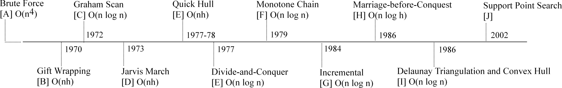
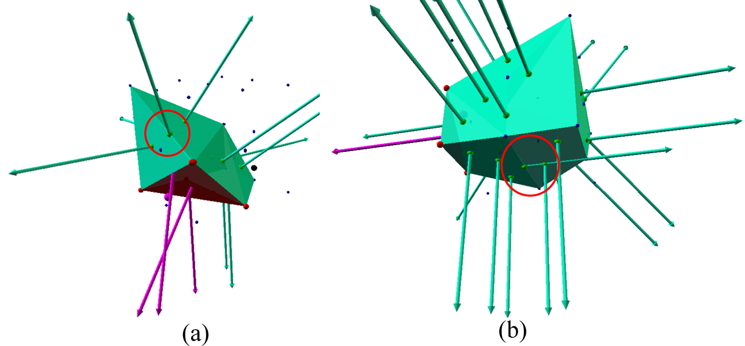
Iterative approach for dealing with coplanar triangles - (a) Calculate the shape centroid, (b) determine outer surface points using support mapping (i.e., the normal from the centroid to each point), (c) project surface points onto a unit sphere (i.e., centroid to surface point fixed length), (d) use the projected surface points to find the interconnected convex hull triangles, and (e) the indexes for each of the projected surface points are the convex hull.
Convex Hulls
Surface Mapping onto a Sphere
Abstract
Writing an uncomplicated, robust, and scalable three-dimensional convex hull algorithm is challenging and problematic. This includes, coplanar and collinear issues, numerical accuracy, performance, and complexity trade-offs. While there are a number of methods available for finding the convex hull based on geometric calculations, such as, the distance between points, but do not address the technical challenges when implementing a usable solution (e.g., numerical issues and degenerate cloud points). We explain some common algorithm pitfalls and engineering modifications to overcome and solve these limitations. We present a novel iterative method using support mapping and surface projection to create an uncomplicated and robust 2d and 3d convex hull algorithm.
keywords:
convex hulls, 3d, 2d, iterative, stable, coplanar, co-linear, reliable, engineering challenges, support mapping, poly, convex, concave, computer generated, interactive1 Introduction
Problem
Convex hull algorithms are an essential multi-discipline technique important to several fields, such as, computer graphics, pattern recognition, medical analysis and design automation [\citenameBarber et al. 1996, \citenameBentley and Shamos 1978, \citenameGregorius 2014, \citenameGraham and Frances Yao 1983]. While multiple approaches are available (e.g., gift wrapping [\citenameChand and Kapur 1970] and divide-and-conquer [\citenamePreparata and Hong 1977]), writing a stable and robust three dimensional implementation is difficult and challenging. Since implementing an algorithm in two dimensions may be easy, but not so for three dimensions [\citenameAvis and Bremner 1995]. We survey a number of techniques and address common problems with convex hull algorithms in practice. Since highly complex and degenerate vertices arise in practice making it difficult to generate a reliable convex hull painlessly. We present a novel method of projecting the convex surface points onto a spherical boundary to remedy numerical sensitivity that produces a simple and reliable solution for both two and three dimensional problems.
Motivation
The mathematics for generating a convex hull from a set of points is well defined, yet there is no de factor standard algorithm or implementation. A number of innovative and interesting concepts have been published that solve the problem, yet the implementation of a robust 3D convex hull algorithm is paved with technical challenges [\citenameAvis and Bremner 1995]. The emphasis of this article is on a novel straightforward algorithm to produce a stable implementation that can be applied in both 2D and 3D easily.
Challenges
While a number of innovative and original convex hull algorithms have been presented, they do not address practical short-comings. Typically, the algorithms are presented in the context of simple test cases, such as, two-dimensions, to explain the working concept. We focus on the engineering enhancement necessary for a real-world implementation. We create a variety of test cases to evaluate the success and failure of the implementation based upon specific problems (see Figure 2). Our solution does not aim for an optimal answer, instead we focus on an uncomplicated method that will generate an accurate convex hull reliably.
Previously
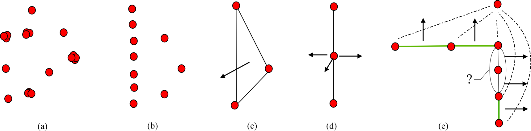
As we would expect, the convex hull problem has been well studied over the past few decades and resulted in a number of solutions (see Figure 1). There are two main class of algorithm for solving convex hull problems: insertion algorithms and pivoting algorithms [\citenameAvis and Bremner 1995]. With our implementation sitting within the insertion regime. An example of a successful insertion method, is the qhull [\citenameBarber et al. 1996, \citenameBarber 1995-2012] algorithm, which solves precision issues caused by coplanar points by merging facets. This includes, merging a point into a coplanar facet, merging concave facets, merging duplicate ridges, and merging flipped facets. Similarly, a pivoting algorithm implementation used by the open source Bullet Physics Engine [\citenameCoumans 2012], is able to generate reliable convex hulls for collision detection problems. The Bullet convex hull implementation is based on Preparata and Hong [\citenamePreparata and Hong 1977] method. This has a time complexity of . Furthermore, to make the algorithm less sensitive to rounding errors, all computations are done with integer math. The algorithm handles degenerate cases, including arbitrary flat and parallel faces. While our method is based upon [\citenameEddy 1977] (QuickHull), but reduces the computation of extremely sensitive collinear and coplanar issues by identifying outer hull points and projecting them onto a common spherical surface.
Contribution
Our main contributions include a definition for a novel convex hull algorithm with less numerical sensitivity and the ability to deal with collinear and coplanar vertices. The algorithm presented in this article offers a number of desirable benefits:
-
✓
Easy to implement (i.e., both 2D and 3D)
-
✓
Terminating condition
-
✓
Can be used with a tolerance in the expansion step for automatic simplification
-
✓
Handle ‘co-planar’ and ‘degenerate’ input data
-
✓
The output mesh is built entirely from the input vertices
-
✓
Can be applied to real-world complex models, not just point clouds
Our approach is the engineering enhancement of mapping the surface points onto a uniform sphere to solve a number of technical shortcomings (e.g., user intervention (tweaking) and numerical issues common with coplanar and collinear faces).
2 Related Work
The convex hull problem has received considerable attention in computational geometry [\citenameGregorius 2014, \citenameGraham and Frances Yao 1983, \citenameKim et al. 2002, \citenameMaus 1984]. Computing a convex hull (or just a “hull”) is one of the first sophisticated geometry algorithms, and there are many variations of it. The most common form of this algorithm involves determining the smallest convex set (called the “convex hull”) containing a discrete set of points. This algorithm also applies to a polygon, or just any set of line segments, whose hull is the same as the hull of its vertex point set. There are numerous applications for convex hulls, for instance, collision avoidance, hidden object determination, and shape analysis.
The most popular hull algorithms are the “Graham scan” algorithm [\citenameGraham 1972] and the “divide-and-conquer” algorithm [\citenamePreparata and Hong 1977]. Implementations of both these algorithms are readily available (see [\citenameO’Rourke 1998]). Both are time algorithms, but the Graham has a low run-time computation overhead in 2D. However, the Graham algorithm does not generalize to 3D and higher dimensions, whereas the divide-and-conquer algorithm has a natural extension. Figure 1 shows the time-line of hull algorithms.
Our work is based around the insertion algorithm concept. Where an initial convex hull approximation is created (i.e., a starting tetrahedron for 3D). We use the support mapping (e.g., see Expanding Polytope Algorithm (EPA) [\citenameKim et al. 2002]) and Quickhull methodology to iteratively grow and encapsulate all the points to form a convex hull.
Which method is best?
It depends on what you want, for example, do you want a 2D or a 3D solution? Are you concerned with run-time speeds or numerical stability and accuracy?
-
-
Parallelizable
-
-
Memory Overhead
-
-
Complexity
-
-
Computational Speed
-
-
Robustness and Numerical Sensitivity
-
-
Number of Dimensions (2D or 3D)
3 Background
Convex Hulls
A convex hull means the smallest convex region which encloses a specified group of points. Technically, it is the smallest convex set containing the points, and can be visualized as a rubber band which wraps around the ‘outside’ points (i.e., all other points must lie within this rubber band [\citenameBarber et al. 1996]). A convex hull is different for dissimilar objects because it depends upon the feature point of every object. For a detailed explanation of Convex Geometry, see Joseph O’Rourke [\citenameO’Rourke 1998]. A convex hull of a set is unique (upto co-linearities). Our method of surface mapping and projecting the points onto a sphere reduces sensitivity and co-linearity ambiguities.
Support Mapping
Support mapping is often used in physics and collision detection [\citenameKim et al. 2002]. The support mapping for a cloud of points given a direction is the point that is farthest in the direction - which simply means finding the point with the maximum dot product (i.e., dot(direction, point). The supporting point in any direction is guaranteed to be on the surface of the convex hull cloud of points. We exploit this concept in our algorithm to efficiently determine the surface points.
No New Vertices
We have an array of points and want to find how they can be connected using triangles to form a convex hull. No extra points are added. The vertices are numbered from to , with each triangle formed by an array of three indices into the vertex array. This is to avoid any numerical drifting. We work with triangle and vertex indices and do not generate any new points.
Centroid
A bounded convex polyhedron is called a polytope. The centroid of a convex polytope as the centroid of its vertices is given by Equation 1.
| (1) |
where the centroid is composed of a set of points . Note, the centroid will be contained within the relative interior of the convex hull.
Algorithm Overview
Our algorithm adopts the well-known QuickHull approach but with additional pre-phase culling and re-mapping of the vertices. It starts by calculating the centroid and performing a support mapping phase to strip inner vertices, the final vertices are then mapped onto a spherical surface using the centroid. From the set of points we use four points to generate a tetrahedron (note - due to support mapping phase, we will not need to discards any internal points as the hull grows). It then iteratively refines the faces of the polyhedron by adding external points, and redistributes the remaining points associated with each face among its children faces. The refinement of a face is performed by selecting the furthest point from its associated points and generating three children triangles. We do not need to worry about concave edge swapping or removing concave vertices.
4 Our Iterative Method
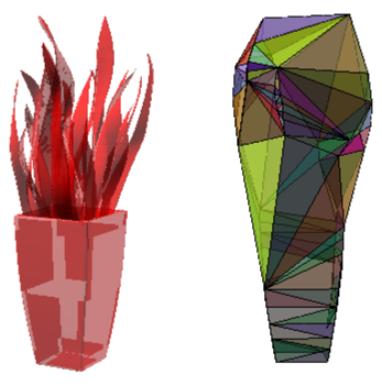
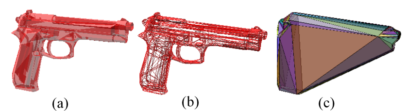
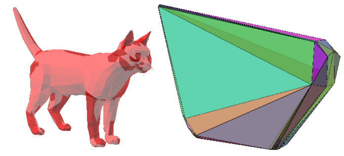
The convex hull algorithm presented in this paper focuses on 3D cases. We are mainly interested in computing convex hulls that are able to solve unforeseen problems for arbitrary clouds of points, which can contain degenerate data, in addition to model scene geometry, such as, complex 3D geometric models (e.g., see Figure 5, Figure 4, and Figure 10).
A preliminary stage is run to strip out and prepair the points. The algorithm starts with a set of points. We remove duplicate points (i.e., points within a predefined tolerance). We calculate the centroid of the set of points). We calculate the normal from the centroid to each point and find the support vertex, and add it to a list. The list will contain a set of points which sit on the convex hull surface. Using the centroid, we project each surface point onto a sphere (i.e., with the centroid the centre of the sphere).
The iterative stage starts by taking the first four vertices and connecting them to form the smallest possible starting closed mesh (i.e., a tetrahedron). After we have set-up the tetrahedron, we iteratively grow the convex hull to encapsulate the rest of the surface points and create the convex hull. We grow the convex hull by going through each of the surface points, and selecting the triangle surfaces that are visible to the point. The visible faces are removed and a new set of faces are added using the edges are are not shared and the new surface point. The key stages are given in Algorithm 1.
-
•
Point inside or outside a convex shape - we can easily determine if a point is inside a convex hull by iterating over all the faces and checking if the point is on the inside of the plane (i.e., dot product). This can be useful for automatically checking if the algorithm failed when developing the implementation.
-
•
Faces that a point can see - we find all the faces that are visible to a point by taking the dot product of the face normal and the point (i.e., front facing if , where is the face normal, is a face vertex, and is the test point).
-
•
Extract edges from a set of faces - we have an array of edges from all the found triangles, any edges that are shared (i.e., ), are thrown away. Then the remaining edges are used to create new triangles (i.e., edge and the new point).
Dynamics
Our method is able to handle unknown sets of points. In addition, due our algorithms iterative nature, we are able to handle changing concave hulls, where points can be added or deleted on-the-fly. Our convex hull algorithm is easily able to update the mesh after each insertion/deletion operation.
Modifications
The algorithm is flexible and can be modified to approach the problem in different ways. For example, instead of iteratively selecting each vertex in the list as we do in our implementation, we could exploit the support mapping concept further by iterating over each face and select the point furthest from the face to iteratively grow the convex polytope. Our algorithm relies on a simple local geometric point-plane test to determine the position of a point with respect to a plane, which is used to pick the triangles to merge the point with. As we have already culled inner points with the support mapping phase. All the points after the support mapping phase are used to create the convex hull surface. Projecting the points onto a sphere reduces co-planar and co-linear issues. Due to the approach the method does not require any swap operations to resolve fold-overs and self-intersections which can complicate the point-plane test and disturb their locality [\citenameStein et al. 2012].
Optimisation
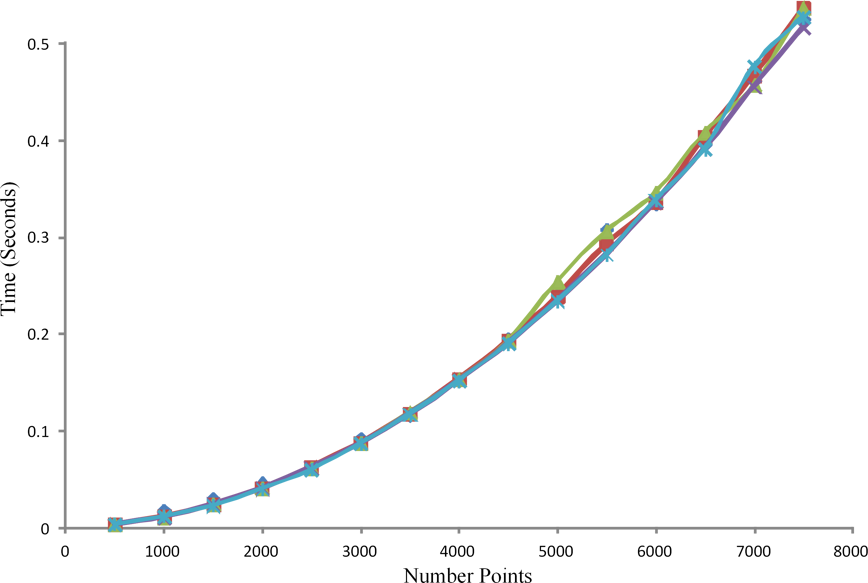
We did not focus on any optimisations, but on a novel solution for providing a robust and easy to implement method that resolves common issues (i.e., reducing coplanar and collinear points). However, the timing results for our implementation are given in Figure 6 to shows the relationship between the number of vertices and the elapsed time. Our iterative algorithm has a time complexity since it is built upon the concept presented by Clarkson and Shor [\citenameClarkson and Shor 1989] which iteratively adds external point to extend the convex polyhedron until the remaining set of points becomes empty.
5 Experimental Results
We implemented the algorithm using floating point precision in C++ within Visual Studio 2013 and Windows-7. We evaluated our implementation using various test scenarios:
- •
-
•
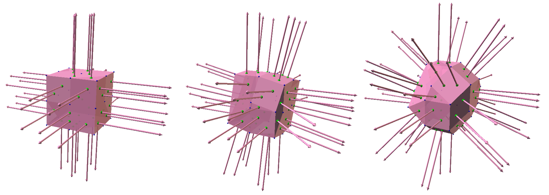
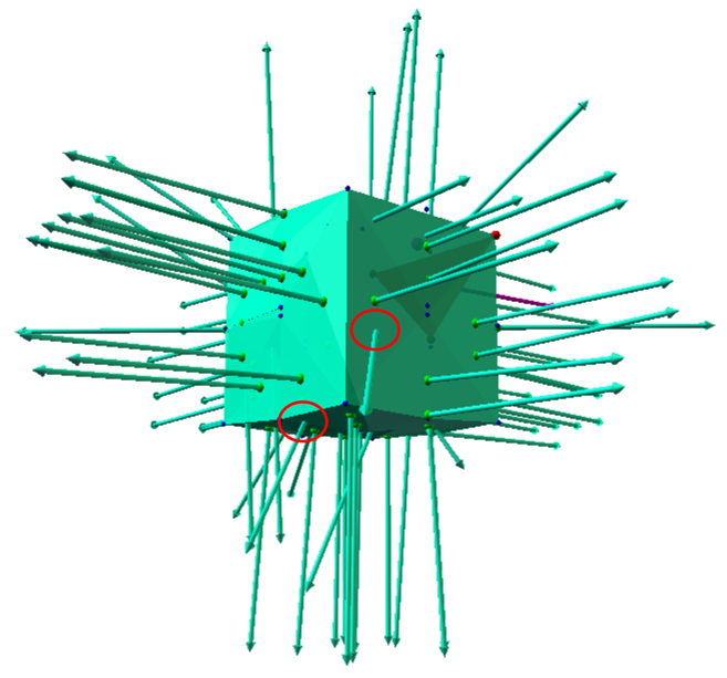
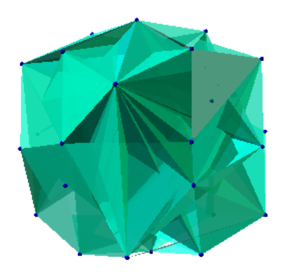
Procedural test case (e.g., Minkowski shape) - Figure 4 - this has the added advantage of generating a wide variety of point data (e.g., degenerate cases that may not naturally occur in preloaded mesh models)
-
•
Random point clusters - i.e., to provide approximate performance metrics for the computational cost versus the number of points - Figure 6
We also emphasis failure cases, as shown in Figure 7, Figure 8, and Figure 9, which are caused when we do not include the additional spherical surface projection phase to reduce co-linear and coplanar issues. A point to note, is our approach reduces accuracy constraints (i.e., numerical sensitivity) for different curved surfaces by projecting the points onto a common spherical lattice. While we can use support mapping to extrapolate the surface vertices, incorrectly expanding the initial tetrahedron, due to numerical sensitivity and coplanar triangles, can produce mesh that engulfs the surface vertices but be concave, as shown in Figure 8.
The randomly generate point set tests of different sizes ranged from 500 to 10000 points. For each size, we generate 5 different datasets and average their run time. Figure 6 shows the run time details and shows our algorithm is .
6 Discussion
A number of factors come into question, such as, computational speed and robustness. On the surface, a convex algorithm may appear elegant and straightforward but can be difficult to implement well. For example, for 3D point clouds, the solution can hit numerical issues for small hulls and computational bottlenecks for large numbers of points (10,000 or more vertices). While fixed-point integer mathematics may help improve robustness, using real-numbers with limited accuracy (e.g., floats or doubles) makes the algorithm much faster but at a cost (e.g., stability and accuracy). We presented a novel generic method that works effectively with real-numbers that is able to deal with coplanar and collinear surfaces without any complex engineering enhancements or user interventions.
Our method works because a convex hull is defined by its vertices. The advantage of our method over other approaches is the surface vertices have already been found during the support mapping phase without overhead. In terms of complexity, it has the benefit of not having to do vertex culling when generating the convex surface. Additionally, when combined with sphere mapping, it reduces the need to perform swap operation to fix the convexity due to concave and other edges.
Acknowledgements
A special thanks to reviewers for taking time to review this article and provide insightful comments and suggestions to help to improve the quality of this article.
References
- [\citenameAndrew 1979] Andrew, A. M. 1979. Another efficient algorithm for convex hulls in two dimensions. Information Processing Letters 9, 5, 216–219.
- [\citenameAvis and Bremner 1995] Avis, D., and Bremner, D. 1995. How good are convex hull algorithms? In Proceedings of the eleventh annual symposium on Computational geometry, ACM, 20–28.
- [\citenameBarber et al. 1996] Barber, C. B., Dobkin, D. P., and Huhdanpaa, H. 1996. The quickhull algorithm for convex hulls. ACM Transactions on Mathematical Software (TOMS) 22, 4, 469–483.
- [\citenameBarber 1995-2012] Barber, C., 1995-2012. http://www.qhull.org/.
- [\citenameBentley and Shamos 1978] Bentley, J. L., and Shamos, M. I. 1978. Divide and conquer for linear expected time. Information Processing Letters 7, 2, 87–91.
- [\citenameBykat 1978] Bykat, A. 1978. Convex hull of a finite set of points in two dimensions. Information Processing Letters 7, 6, 296–298.
- [\citenameChand and Kapur 1970] Chand, D. R., and Kapur, S. S. 1970. An algorithm for convex polytopes. Journal of the ACM (JACM) 17, 1, 78–86.
- [\citenameClarkson and Shor 1989] Clarkson, K. L., and Shor, P. W. 1989. Applications of random sampling in computational geometry, ii. Discrete & Computational Geometry 4, 1, 387–421.
- [\citenameCoumans 2012] Coumans, E., 2012. Bullet physic sdk manual.
- [\citenameEddy 1977] Eddy, W. F. 1977. A new convex hull algorithm for planar sets. ACM Transactions on Mathematical Software (TOMS) 3, 4, 398–403.
- [\citenameGraham and Frances Yao 1983] Graham, R. L., and Frances Yao, F. 1983. Finding the convex hull of a simple polygon. Journal of Algorithms 4, 4, 324–331.
- [\citenameGraham 1972] Graham, R. L. 1972. An efficient algorith for determining the convex hull of a finite planar set. Information processing letters 1, 4, 132–133.
- [\citenameGregorius 2014] Gregorius, D. 2014. Implementing quickhull. Game Developers Conference (Valve Software) in San Francisco.
- [\citenameJarvis 1973] Jarvis, R. A. 1973. On the identification of the convex hull of a finite set of points in the plane. Information Processing Letters 2, 1, 18–21.
- [\citenameKallay 1984] Kallay, M. 1984. The complexity of incremental convex hull algorithms in rd. Information Processing Letters 19, 4, 197.
- [\citenameKim et al. 2002] Kim, Y. J., Lin, M. C., and Manocha, D. 2002. Deep: Dual-space expansion for estimating penetration depth between convex polytopes. In Robotics and Automation, 2002. Proceedings. ICRA’02. IEEE International Conference on, vol. 1, IEEE, 921–926.
- [\citenameKirkpatrick and Seidel 1986] Kirkpatrick, D. G., and Seidel, R. 1986. The ultimate planar convex hull algorithm? SIAM journal on computing 15, 1, 287–299.
- [\citenameMaus 1984] Maus, A. 1984. Delaunay triangulation and the convex hull ofn points in expected linear time. BIT Numerical Mathematics 24, 2, 151–163.
- [\citenameO’Rourke 1998] O’Rourke, J. 1998. Computational geometry in C. Cambridge university press.
- [\citenamePreparata and Hong 1977] Preparata, F. P., and Hong, S. J. 1977. Convex hulls of finite sets of points in two and three dimensions. Communications of the ACM 20, 2, 87–93.
- [\citenameStein et al. 2012] Stein, A., Geva, E., and El-Sana, J. 2012. Cudahull: Fast parallel 3d convex hull on the gpu. Computers & Graphics 36, 4, 265–271.