Novel resistive charge-multipliers for dual-phase LAr-TPCs: towards stable operation at higher gains
Abstract
Cryogenic versions of Resistive WELL (RWELL) and Resistive Plate WELL (RPWELL) detectors have been developed, aimed at stable avalanche multiplication of ionization electrons in the vapor phase of LAr (dual-phase TPC). In the RWELL, a thin resistive DLC layer deposited on top of an insulator is inserted in between the electron multiplier (THGEM) and the readout anode; in the RPWELL, a resistive ferrite plate is directly coupled to the THGEM. Radiation-induced ionization electrons in the liquid are extracted into the gaseous phase. They drift into the THGEM’s holes where they undergo charge multiplication. Embedding resistive materials into the multiplier proved to enhance operation stability due to the mitigation of electrical discharges - thus allowing operation at higher charge gain compared to standard THGEM (a.k.a. LEM) multipliers. We present the detector concepts and report on the main preliminary results.
1 Introduction
In the last years, noble-liquid detectors have predominantly gained the scene in the field of particle and astroparticle physics as a leading technology: examples can be found in the context of neutrino physics [1, 2], dark matter searches [3, 4, 5, 6, 7, 8, 9] and rare events searches such as [10].
A widespread concept is the dual-phase TPC [11, 12]: charges deposited in a liquefied noble element are extracted into its vapor phase; they induce electroluminescence (EL) photons that are detected by photo-sensors. Early attempts to multiply charges in Ar vapor through LEM amplification (targeting neutrino experiments) suffered from low charge gain (G20 in a prototype of [13] and G1.9 in a one [14], both irradiated with cosmic rays at 87 K, 0.98 bar) - due to electrical instabilities.
The possibility of enhancing the ionization signal through charge multiplication would allow a direct increase of signal-to-noise () compared to charge-collection in liquid phase, thus reducting the detection energy threshold.
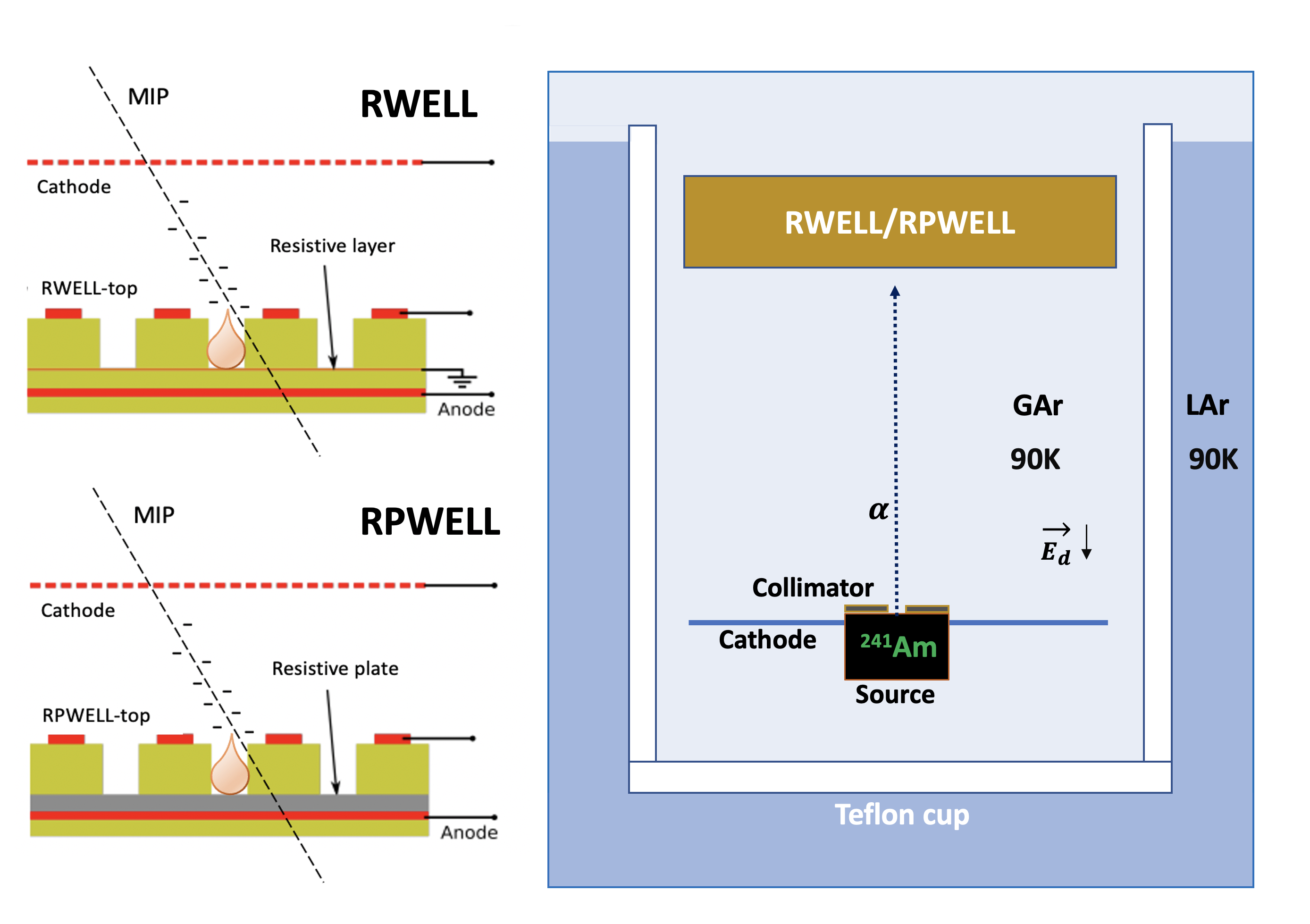
In light of this, we propose to embed discharge-mitigating resistive materials into the detector assemblies based on Thick Gaseous Electron Multiplier (THGEM)-like concepts [15, 16, 17, 18] in order to enhance gain and electrical stability. Following the considerable experience gained from operation at room temperature, we opted for the Resistive WELL (RWELL) [19] and the Resistive Plate WELL (RPWELL) [20]; they resort, respectively, to a resistive film deposited on an insulator and to a resistive plate, directly coupled to a THGEM electrode in both cases (Fig.1-left). A successful operation of an RPWELL detector at liquid xenon temperature (163 K) was already reported in a gaseous admixture of Ne/CH4 [21].
In this work, we describe the principles of both multipliers and present, for the first time, the results of their operation in pure argon vapor at 90 K.
2 Experimental Setup and Methodology
In the cryo-RWELL, a perforated electrode (a 0.8 mm-thick THGEM in this case, 0.5 mm diameter holes distributed in a hexagonal pattern with 1 mm pitch, in size) is screwed to the readout anode via a resistive layer of Diamond-Like-Carbon (DLC) [22] deposited on top of a 0.1 mm-thick insulator. Details about the properties of these materials and their surface resistivity at cryogenic temperature can be found in [23].
In the cryo-RPWELL, the multiplier is directly coupled to the anode through a resistive ceramic plate made of Yttria-Stabilized-Zirconia (YSZ) and hematite (Fe2O3) [24] and fixed with screws. Ceramics samples with the right resistivities (optimal bulk resistivity range: 109-cm) were engineered at the Instituto de Cerámica de Galicia in Spain (ICG) and characterized for operation at 90 K.
The detector assembly was inserted inside a Teflon cup immersed in the liquid argon cryostat (Fig.1-right), and operated in gaseous argon at 90 K. Prior to any measurement, the system was vacuum-pumped for at least 24 h reaching a pressure of -110-4 mbar. During operation, the gas was recirculated and purified with a hot getter222Entegris HotGetter PS3-MT3-R-2 in order to grant a nominal impurity content of the order of 1 ppb. The detector was irradiated with -particles of 5.5 MeV from an 241Am source collimated and attenuated to 4 MeV by a 12 mylar foil. The rate of the source after collimation was approximately 10 Hz.
Radiation-induced ionization electrons generated in the gas were transferred into the electrode’s holes. The presence of a high local electric field led to avalanche multiplication in the holes. The avalanche-charge evacuation was realized differently in the two detectors: in the RWELL, the amplified charge propagated to the ground sideways across the resistive layer; in the RPWELL, the amplified charge traveled through the resistive plate directly to the anode.
For both processes, signals were induced on the anode and recorded with a standard electronic chain comprising a charge-sensitive preamplifier333Cremat: Model CR-110 with CR-150-R5 evaluation board, a linear amplifier444Ortec Model 450 and an MCA555Amptek MCA 8000D. High voltages were supplied to all the electrodes through a power supply666CAEN N1471H.
Measurements were performed by recording spectra from the charge-sensitive preamplifier, linear amplifier, and MCA electronic chain. For each voltage configuration, about 1k spectra of 120 s were acquired. Each spectrum was fitted with a Gaussian function in order to extract the mean and standard deviation of the main peak in the distribution. To estimate the gain of the detector, a measurement in collection mode was performed. The gain of the detector G was estimated by dividing the mean of the Gaussian peak in the spectrum with amplification PAmplif by the mean value of the collection peak PColl, . Prior to each measurement, the detector was stabilized for several hours in order to remove the charging-up effect.
3 Results
In the following, we report on some preliminary results.
3.1 Cryo-RWELL
An extensive study of the properties of DLC films was conducted at cryogenic temperature and summarized in [23]. In the current RWELL detector, a layer with surface resistivity RS equal to 20 G at 90 K was employed. The latter was selected after several failed attempts to stably operate the RWELL with a layer of RS=10 M, as per experience at room temperature [19].
Gain Discharge Probability
The RWELL gain characterization was performed at three different temperatures: 90 K, 100 K and 115 K. The warming-up was performed in a controlled way to ensure thermal stability. The pressure inside the cryostat was kept at 1.2 bar throughout the entire study. The drift field was kept constant, Ed= 0.5 kV/cm. It is important to mention that the DLC resistivity decreased while increasing temperature, from 20 G at 90 K to 10 G at 100 K till 3.5 G at 115 K. The RWELL gain as a function of VRWELL at different temperatures is reported in Fig.2(a).
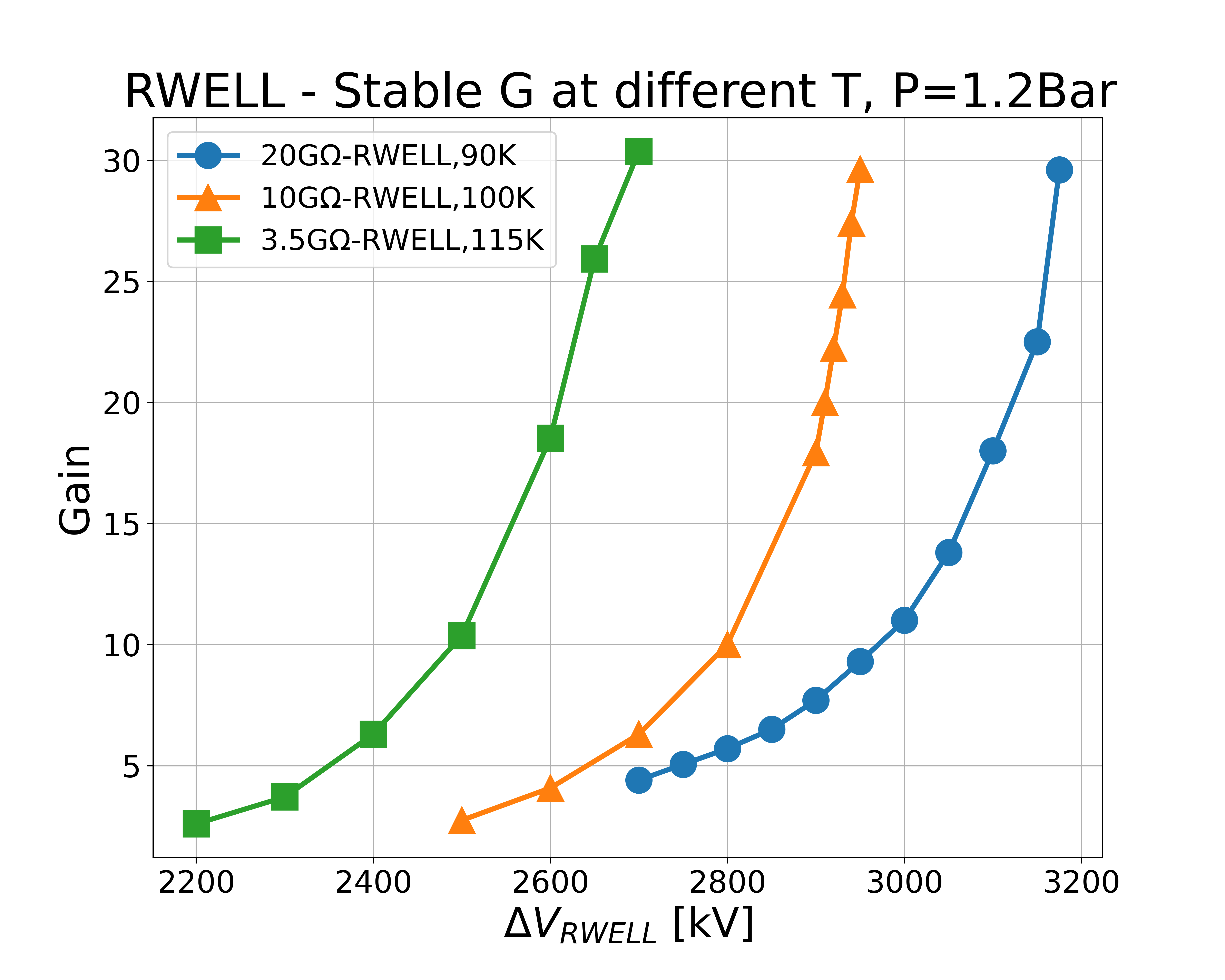
The three curves manifest the same exponential trend, suggesting the presence of avalanche multiplication. A maximum stable gain close to 30 was achieved in the three cases. The left-shift at higher temperature is due to the lower gas density. Above a detector gain close to 18, the presence of occasional discharges was observed. The detector was able to sustain them and its performance was not degraded. Above 3.2 kV, the presence of self-sustained currents across the amplification stage prevented further operation.
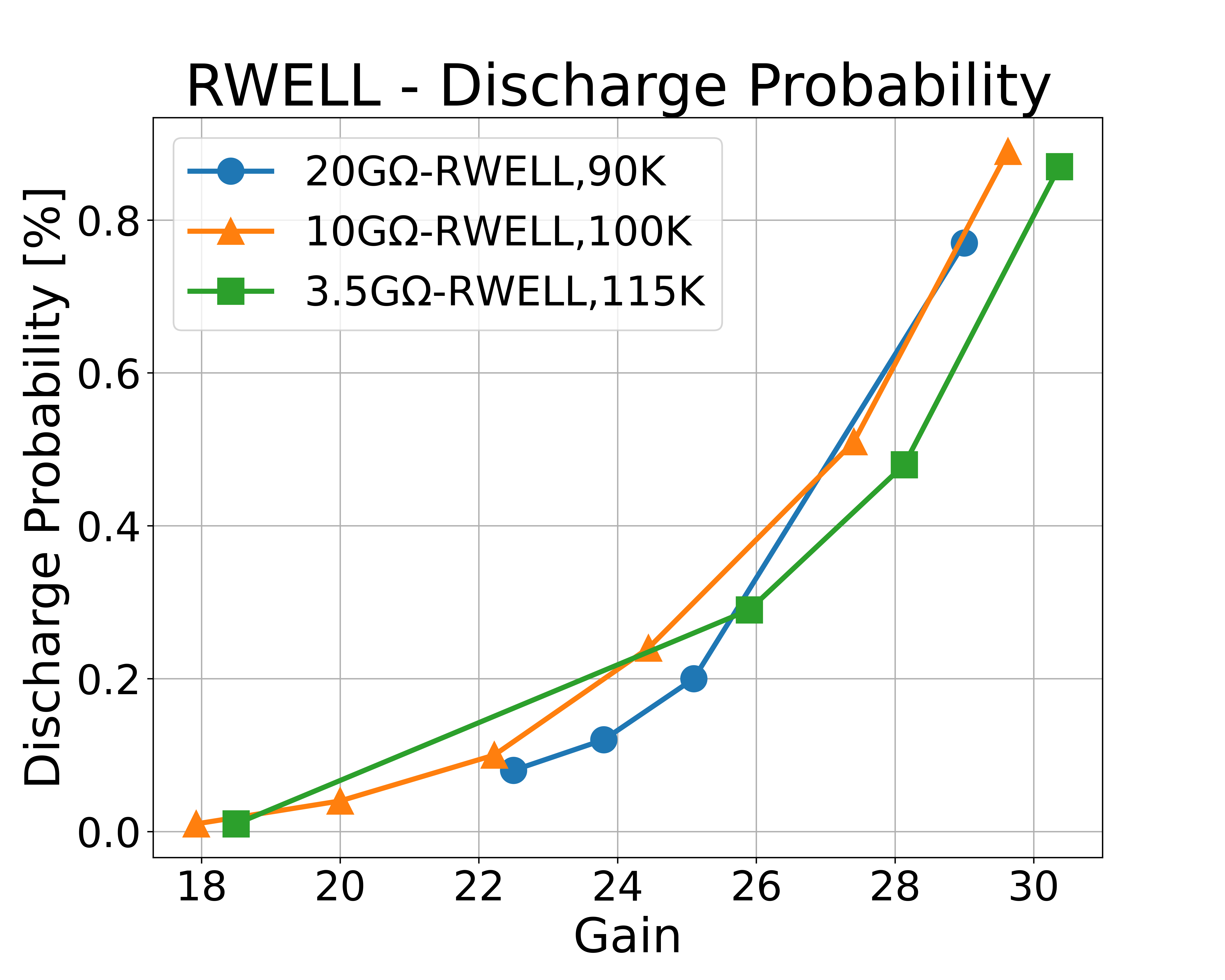
The discharge probability is defined here as the number of discharges measured in a specific time frame, relative to the the rate of alpha particles passing through the collimator. In Fig.2(b), the discharge probability as a function of gain is depicted, for different temperatures and resistivity values. It is worth noting that the probability trend is very similar despite the different temperature conditions and a 1 discharge probability is achieved at the maximum voltage for all three cases. This is in line with room temperature results [25].
3.2 Cryo-RPWELL
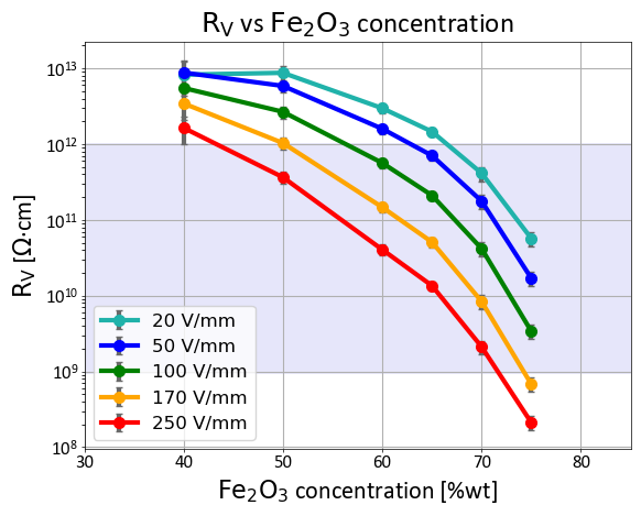
The availability of novel ceramic materials with a bulk resistivity RV comprised in the range 109-10cm at 90 K paved the way for the construction of the cryo-RPWELL. In fact, values of RV in this range were found to be sufficient to fully quench discharges at room temperature [26]. In Fig.3, the RV of several ceramic plates is reported as a function of Fe2O3 concentration for different applied fields at 77 K. The resistive plate in the RPWELL detector over the relevant range is expected to be at ground and get minimally affected by the presence of discharges.
The voltage applied across the multiplier was scanned in the range of VRPWELL=2.7-3.15 kV. The stable gain curve with alpha particles at 90 K, 1.2 bar is given in Fig.4(a). The discharge probability as a function of gain at 90 K is reported in Fig.4(b).
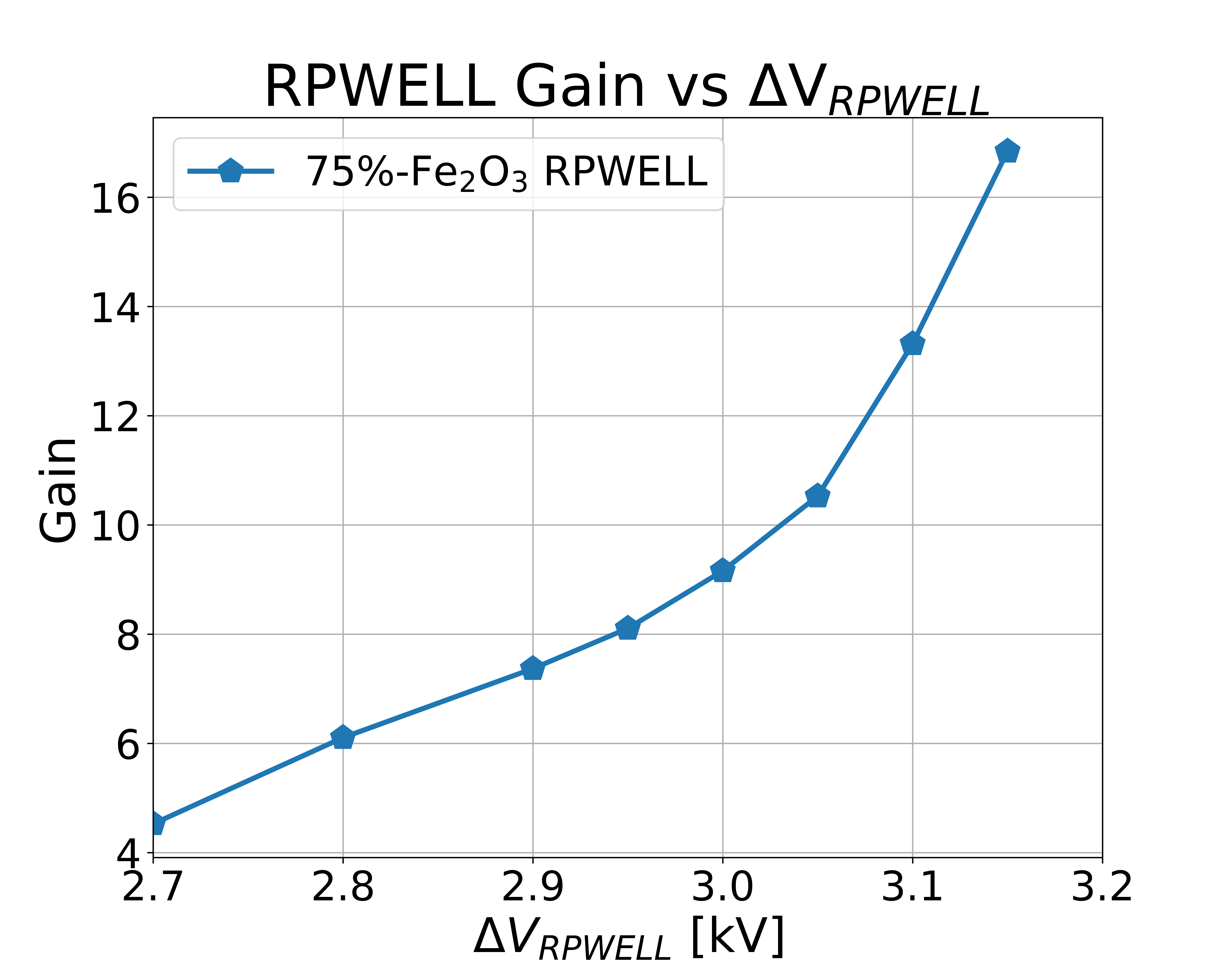
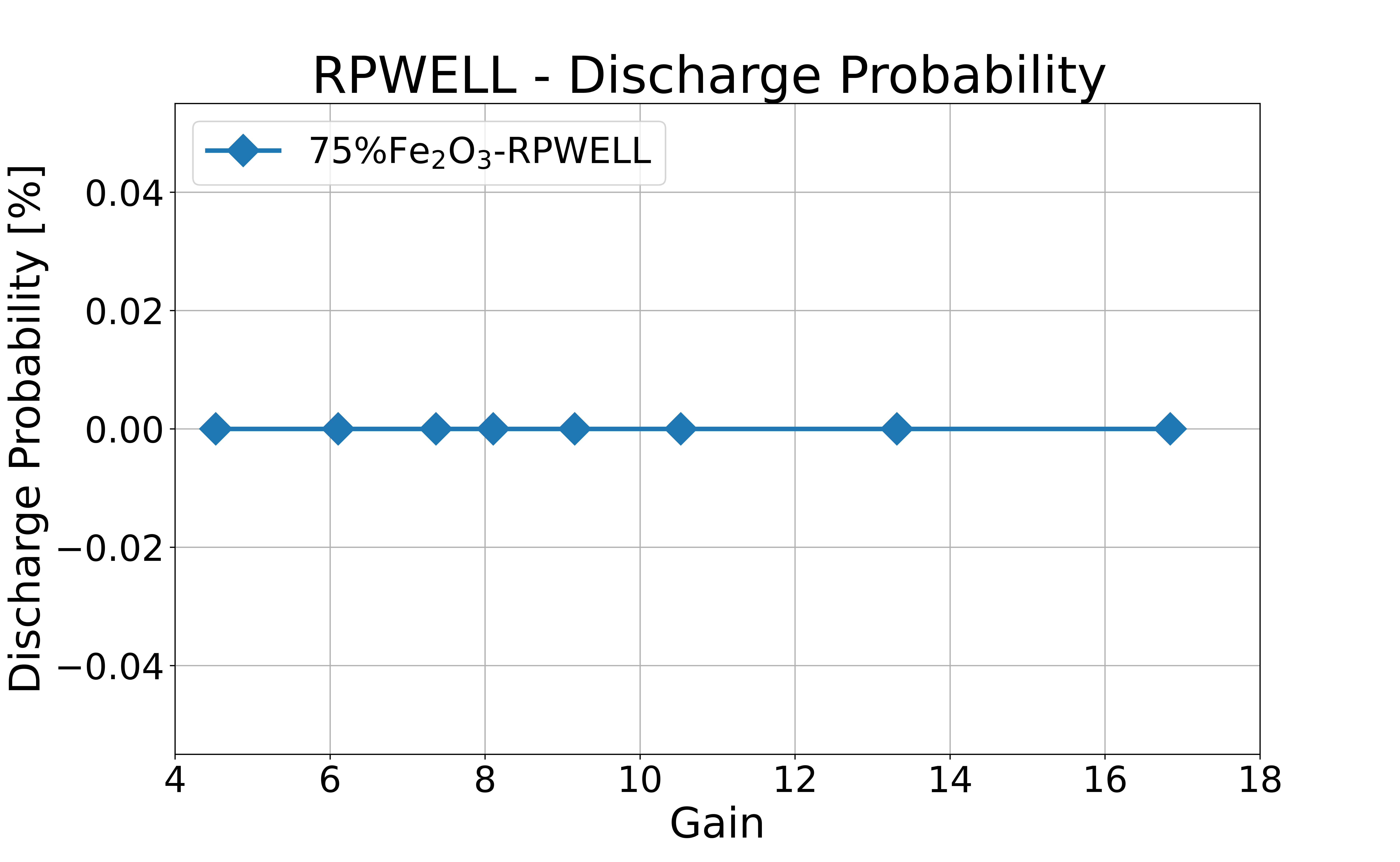
It is possible to see that the RPWELL is able to operate with a stable gain close to 16 in discharge-free mode.
The investigation of this concept is still ongoing.
4 Discussion
The cryo-RWELL and cryo-RPWELL concepts, incorporating resistive anodes, may evolve in the future into viable charge sensors for large-volume dual-phase radiation detectors. These concepts have been validated with small prototypes in the vapor phase of LAr.
A comparison with a standard 0.8 mm thick THGEM followed by 2 mm induction gap was also carried out, see Fig.5.
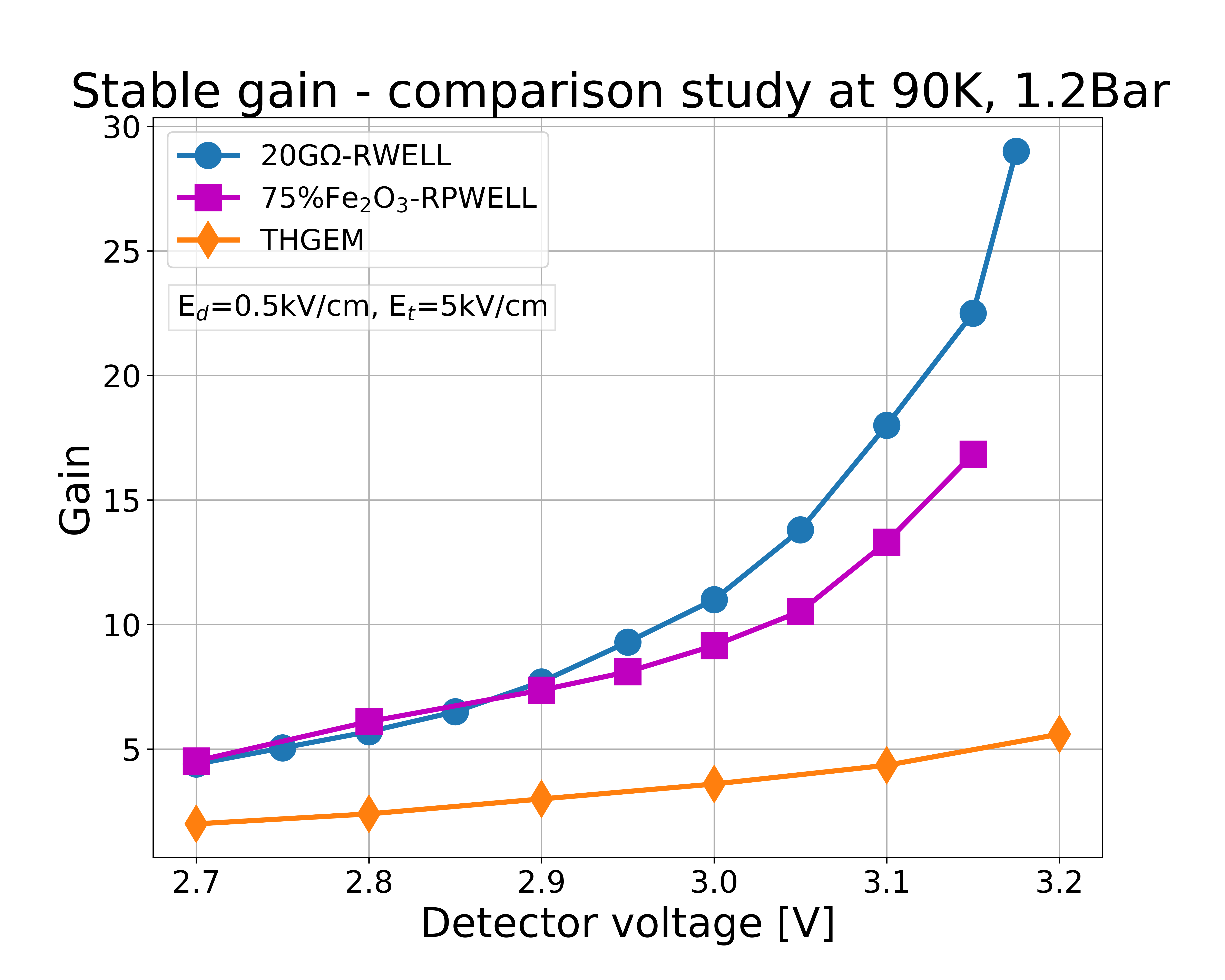
These preliminary results show that embedding resistive anodes into the detector improves its performance and protects the electronics from electrical instabilities. A detailed study of the maximal stable gain achieved by the RWELL/RPWELL is currently ongoing. As an observation, the gain of resistive anodes is 2.5-5 times higher than the gain of a THGEM operated in the same setup under the same conditions. Although a similar gain was observed in 10x10cm2 LEM operated in LAr vapor with no resistive materials, a direct comparison cannot be made due to possible differences in operating conditions and gas purity; considerations about the scalability of DLC layers vs resistive plates will be addressed in a future study. In conclusion, while showing promising results for both RWELL/RPWELL, the data presented here raises interesting questions regarding the role played by the resistive materials in the discharge quenching process - e.g., is there a difference in the quenching mechanism between the RWELL and the RPWELL? Further studies will follow.
5 Acknowledgements
This work was supported by Sir Charles Clore Prize, by Martin Kushner Schnur, by the Nella and Leon Benoziyo Center for High Energy Physics, and by RD51 funds through its ‘common project’ initiative. We acknowledge as well financial support from Xunta de Galicia (Centro singular de investigación de Galicia, accreditation 2019- 2022), and by the “María de Maeztu” Units of Excellence program MDM-2016-0692. DGD was supported by the Ramón y Cajal program (Spain) under contract number RYC-2015-18820.
References
- [1] A. Ereditato and A. Rubbia, The liquid argon tpc: a powerful detector for future neutrino experiments and proton decay searches, Nuclear Physics B - Proceedings Supplements 154 (2006) 163.
- [2] DUNE collaboration, Long-Baseline Neutrino Facility (LBNF) and Deep Underground Neutrino Experiment (DUNE): Conceptual Design Report, Volume 3: Long-Baseline Neutrino Facility for DUNE June 24, 2015, 1601.05823.
- [3] L. Baudis, Direct dark matter detection: The next decade, Physics of the Dark Universe 1 (2012) 94.
- [4] E. Aprile and T. Doke, Liquid xenon detectors for particle physics and astrophysics, Reviews of Modern Physics 82 (2010) 2053.
- [5] D.N. McKinsey and for the LZ Collaboration, The lz dark matter experiment, Journal of Physics: Conference Series 718 (2016) 042039.
- [6] J. Aalbers, F. Agostini, M. Alfonsi, F. Amaro, C. Amsler, E. Aprile et al., DARWIN: towards the ultimate dark matter detector, Journal of Cosmology and Astroparticle Physics 2016 (2016) 017.
- [7] C.E. Aalseth, F. Acerbi, P. Agnes, I.F.M. Albuquerque, T. Alexander, A. Alici et al., DarkSide-20k: A 20 tonne two-phase LAr TPC for direct dark matter detection at LNGS, The European Physical Journal Plus 133 (2018) .
- [8] E. Aprile, K. Arisaka, F. Arneodo, A. Askin, L. Baudis, A. Behrens et al., The XENON100 dark matter experiment, Astroparticle Physics 35 (2012) 573.
- [9] E. Aprile, , J. Aalbers, F. Agostini, M. Alfonsi, F.D. Amaro et al., The XENON1t dark matter experiment, The European Physical Journal C 77 (2017) .
- [10] S. Mihara, Meg liquid xenon detector, Journal of Physics: Conference Series 308 (2011) 012009.
- [11] V. Chepel and H. Araú jo, Liquid noble gas detectors for low energy particle physics, Journal of Instrumentation 8 (2013) R04001.
- [12] B. Aimard, C. Alt, J. Asaadi, M. Auger, V. Aushev, D. Autiero et al., A 4 tonne demonstrator for large-scale dual-phase liquid argon time projection chambers, Journal of Instrumentation 13 (2018) P11003.
- [13] C. Cantini, L. Epprecht, A. Gendotti, S. Horikawa, L. Periale, S. Murphy et al., Performance study of the effective gain of the double phase liquid argon lem time projection chamber, Journal of Instrumentation 10 (2015) P03017.
- [14] WA105 collaboration, Performance study of a 3×1×1 m3 dual phase liquid Argon Time Projection Chamber exposed to cosmic rays, JINST 16 (2021) P08063 [2104.08227].
- [15] A. Breskin, R. Alon, M. Cortesi, R. Chechik, J. Miyamoto, V. Dangendorf et al., A concise review on THGEM detectors, Nuclear Instruments and Methods in Physics Research Section A: Accelerators, Spectrometers, Detectors and Associated Equipment 598 (2009) 107.
- [16] R. Bellazzini, M. Bozzo, A. Brez, G. Gariano, L. Latronico, N. Lumb et al., The well detector, Nuclear Instruments and Methods in Physics Research Section A: Accelerators, Spectrometers, Detectors and Associated Equipment 423 (1999) 125.
- [17] A. Breskin, M. Cortesi, R. Alon, J. Miyamoto, V. Peskov, G. Bartesaghi et al., The thgem: A thick robust gaseous electron multiplier for radiation detectors, Nuclear Instruments and Methods in Physics Research Section A: Accelerators, Spectrometers, Detectors and Associated Equipment 623 (2010) 132.
- [18] S. Bressler, L. Moleri, A. Jash, A. Tesi and D. Zavazieva, The thick gas electron multiplier and its derivatives: Physics, technologies and applications, Progress in Particle and Nuclear Physics (2023) 104029.
- [19] L. Arazi, M. Pitt, S. Bressler, L. Moleri, A. Rubin and A. Breskin, Laboratory studies of THGEM-based WELL structures with resistive anode, Journal of Instrumentation 9 (2014) P04011.
- [20] A. Rubin, L. Arazi, S. Bressler, L. Moleri, M. Pitt and A. Breskin, First studies with the resistive-plate WELL gaseous multiplier, Journal of Instrumentation 8 (2013) P11004.
- [21] A. Roy, M. Morales, I. Israelashvili, A. Breskin, S. Bressler, D. Gonzalez-Diaz et al., First results of resistive-plate well (RPWELL) detector operation at 163 k, Journal of Instrumentation 14 (2019) P10014.
- [22] J. Robertson, Properties of diamond-like carbon, Surface and Coatings Technology 50 (1992) 185.
- [23] S. Leardini, Y. Zhou, A. Tesi, M. Morales, D. González-Díaz, A. Breskin et al., Diamond-like carbon coatings for cryogenic operation of particle detectors, Nucl. Instrum. Meth. A 1049 (2023) 168104 [2209.15509].
- [24] M. Morales, C. Pecharromán, G. Mata-Osoro, L.A. Díaz and J.A. Garzón, Conductivity and charge depletion aging of resistive electrodes for high rate rpcs, Journal of Instrumentation 8 (2013) P01022.
- [25] A. Jash, L. Moleri and S. Bressler, Electrical breakdown in thick-GEM based WELL detectors, Journal of Instrumentation 17 (2022) P11004.
- [26] A. Jash, L. Moleri and S. Bressler, Electrical discharges and their effect in a resistive plate well detector, Nuclear Instruments and Methods in Physics Research Section A: Accelerators, Spectrometers, Detectors and Associated Equipment 1045 (2023) 167540.