figuret
Tracking a Spin-Polarized Superconducting Bound State across a Quantum Phase Transition
Abstract
The magnetic exchange coupling between magnetic impurities and a superconductor induce so-called Yu-Shiba-Rusinov (YSR) states which undergo a quantum phase transition (QPT) upon increasing the exchange interaction beyond a critical value. While the evolution through the QPT is readily observable, in particular if the YSR state features an electron-hole asymmetry, the concomitant change in the ground state is more difficult to identify. We use ultralow temperature scanning tunneling microscopy to demonstrate how the change in the YSR ground state across the QPT can be directly observed for a spin- impurity in a magnetic field. We observe a change in the excitation spectrum from the doublet ground state in the free spin regime (two spectral features) to the singlet ground state in the screened spin regime (four spectral features). We also identify a transition regime, where the YSR excitation energy is smaller than the Zeeman energy. We thus provide a straightforward way for unambiguously identifying the ground state of a spin- YSR state.
Unpaired spins in impurities coupled to a superconductor induce discrete sub-gap excitations, the Yu-Shiba-Rusinov (YSR) states Yu (1965); Shiba (1968); Rusinov (1969); Yazdani et al. (1997), through an exchange interaction produced locally via impurity-superconductor coupling. If the exchange coupling increases beyond a critical value the YSR states undergo a quantum phase transition (QPT) such that the initially free spin becomes screened Balatsky et al. (2006); Heinrich et al. (2018). The transition through a QPT has been attributed to a reversal in the asymmetry of the spectral weight of electron and hole excitation components, which are readily observed in a scanning tunneling microscope (STM) Farinacci et al. (2018); Küster et al. (2021); Franke et al. (2011); Kamlapure et al. (2021); Malavolti et al. (2018); Bauer et al. (2013); Chatzopoulos et al. (2021). This reversal in spectral weight holds, however, only in the simplest approximation that all higher order effects are ignored. The spectral weight does not reflect the particle-hole asymmetry if, for example, the system is already in the resonant Andreev reflection regime Ruby et al. (2015) or tunneling paths are interfering Farinacci et al. (2020). Most crucially, it is a priori not possible with the STM to identify to which side of the quantum phase transition the system belongs.
A straightforward albeit indirect and not entirely unambiguous way to manipulate the ground state of an atomic scale YSR resonance is to change the impurity-substrate coupling if the YSR impurity is susceptible to the atomic forces acting between tip and sample in the STM tunnel junction Farinacci et al. (2018); Brand et al. (2018); Malavolti et al. (2018); Kezilebieke et al. (2019); Huang et al. (2020a). The ambiguity arises because it is not a priori clear whether the impurity-substrate coupling increases or decreases upon reducing the tip-sample distance. This calls for an unambiguous manifestation going beyond auxiliary measurements Huang et al. (2020a) to distinguish the ground state of the YSR excitation.
An independent observation identifying the ground state of the system across the QPT can be made by placing the YSR state in a Josephson junction (0- transition) Karan et al. (2022). Also, the zero-field splitting of YSR excitations due to effective anisotropic interactions in high-spin systems has been used to assign the ground state of different molecules on either side of the QPT Hatter et al. (2015). While different YSR states have been studied with the STM in the presence of a magnetic field Žitko et al. (2011); Cornils et al. (2017); Schneider et al. (2021); Machida et al. (2022), a continuous evolution of the YSR state across the QPT in a magnetic field has not been observed like in mesoscopic systems Lee et al. (2014). The challenge in observing a sizeable Zeeman splitting in a YSR state lies with the typically rather small critical magnetic field that quenches superconductivity. Here, we circumvent this problem by placing the YSR state at the tip apex Karan et al. (2022); Huang et al. (2020b), where the superconductor is dimensionally confined, such that the critical field is considerably enhanced (Meservey-Tedrow-Fulde (MTF) effect) Meservey et al. (1970); Chen et al. (2008); Eltschka et al. (2014). We use an ultralow temperature STM at 10 mK to reduce the thermal energy much below the Zeeman energy and trace the spectral signatures associated with the changes in the YSR ground state across the QPT by continuously changing the impurity-substrate coupling (see Fig. 1(a)).
A typical spectrum measured with a YSR functionalized superconducting vanadium tip on a superconducting V(100) sample at 10 mK is shown in Fig. 1(b). The electron and hole parts of the YSR state with energy appear at a bias voltage as prominent peaks. Due to the superconducting sample, the YSR peaks shift by the sample gap away from zero bias voltage. The coherence peaks at , which is the sum of the tip and sample gaps, are small indicating a dominant transport channel through the YSR state. We change the impurity-substrate coupling by varying the tip-sample distance, which modifies the atomic force acting on the impurity Ternes et al. (2008a, 2011). This concomitantly changes the exchange coupling causing an evolution of the YSR energy as shown in Fig. 1(c). At a critical exchange coupling , when the YSR energy is at zero, the system moves across a QPT such that the free impurity-spin () becomes screened () bringing about a change in the fermionic parity of the ground state Sakurai (1970). This scenario is schematically depicted in the insets of Fig. 1(c), where a doublet () transforms into a singlet () leading to the screening of the impurity spin.
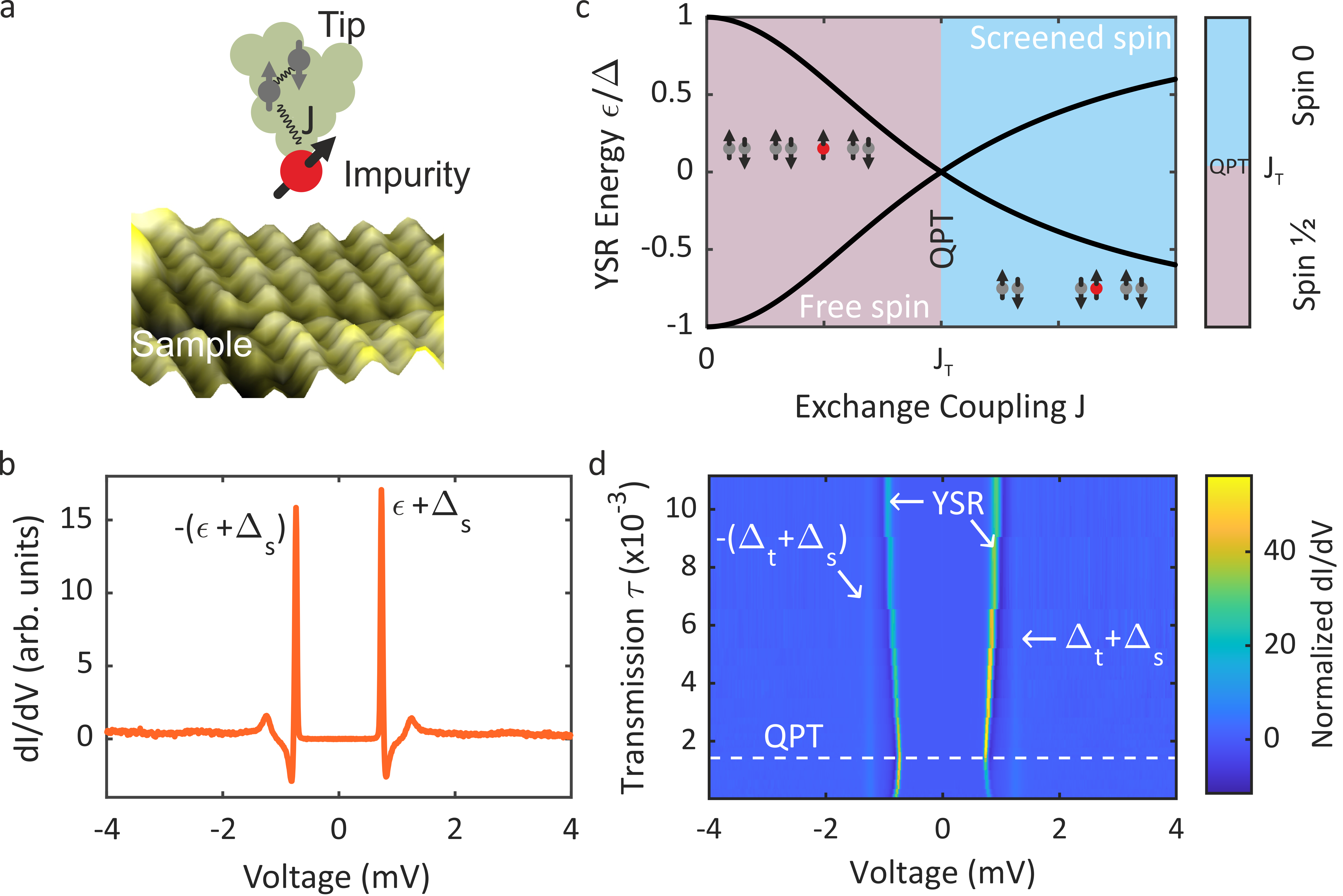
Figure 1(d) shows how the YSR peaks evolve with the junction transmission (: normal state conductance; : conductance quantum with being the elementary charge and Planck’s constant). The YSR peaks evolve continuously reaching the bias voltage closest to zero at the QPT. Because of the shift of the YSR state by the superconducting gap of the other electrode (the substrate in this case) in the conductance spectrum, the zero crossing at the QPT is not observed directly. An inversion of the asymmetry in the YSR peak intensities is clearly visible, when the electron and hole excitation components switch sides across the QPT. However, it is not possible to judge from the tunneling spectra alone, on which side of the QPT the system is.
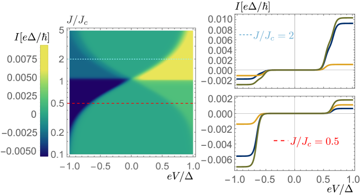
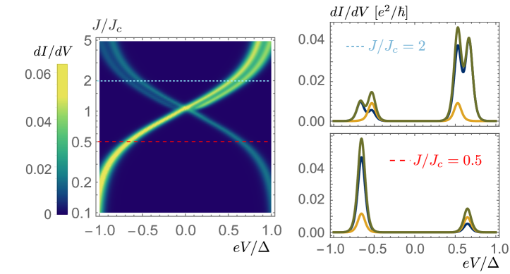
Turning on a magnetic field, the -state splits into two levels. In the free spin regime, the spin down state (see Fig. 3(a)) turns into the non-degenerate ground state. Its higher lying spin-flipped partner is thermally not populated due to the extremely low temperature of 10 mK. Only the screened -state appears as a transport channel lying energectically above the doublet. Since it does not change in the magentic field, it induces only one spectral feature on either side of the Fermi level. In contrast, beyond the QPT, the -state becomes the ground state and charge transfer is possible through the spin-doublet (details see below). This can be seen in Fig. 2(a), which shows two representative differential conductance spectra on either side of the QPT at a magnetic field of 750 mT. The orange spectrum shows two features (one on either side of the Fermi level), which indicates that the system is in the free spin regime. The sample is already normal conducting at 750 mT, such that there is no shift of the YSR peak by . The YSR tip is still superconducting due to the MTF effect. In the screened spin regime, ground state and excited state are interchanged, such that now two transitions into the upper and lower Zeeman split levels are possible from the single ground state level. As a result, the spectrum measured in the screened spin regime (the blue curve) shows four spectral features (two on either side of the Fermi level). This distinction is only possible, if the Zeeman energy is much larger than the thermal energy. If this is not the case, two spectral features will be visible on either side of the QPT and a more detailed analysis of the spectral weight has to be done to distinguish the ground states Hatter et al. (2015).
As has been demonstrated before Huang et al. (2020a, b); Karan et al. (2022); Farinacci et al. (2018); Küster et al. (2021); Franke et al. (2011); Kamlapure et al. (2021); Malavolti et al. (2018); Bauer et al. (2013); Chatzopoulos et al. (2021), we exploit the changing atomic forces in the tunnel junction when reducing the tip-sample distance to change the impurity-superconductor coupling thereby shifting the YSR state energy. We note that depending on the particular system, the impurity-substrate coupling can increase or decrease during tip approach. The evolution of the YSR state through the QPT for two different magnetic fields are shown in Figs. 2(b) and (c) as function of the tunnel junction transmission (i.e. junction conductance). Here, we can see directly that the screened spin regime featuring four spectral peaks is at higher transmissions and the free spin regime featuring only two spectral peak is at lower transmissions. This actually implies that the impurity-superconductor coupling increases with increasing transmission, which is verified by an additional analysis of the Kondo effect at higher magnetic fields below. The data in Fig. 2(b) was taken at 750 mT, which results in a stronger Zeeman splitting than the data in Fig. 2(c), which was taken at 500 mT having less Zeeman splitting. Still, both data sets show qualitatively the same behavior across the QPT as expected from the discussion above.
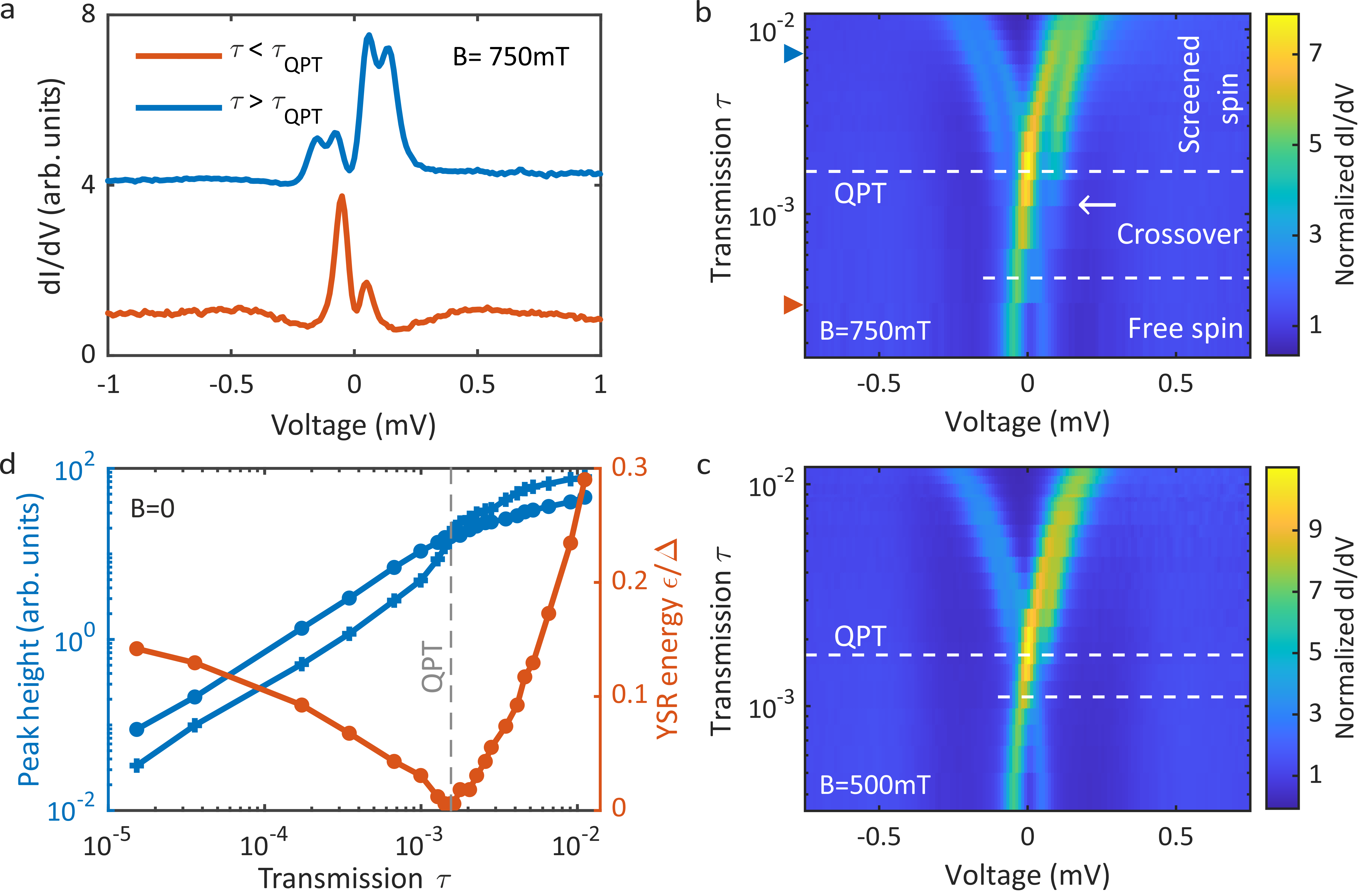
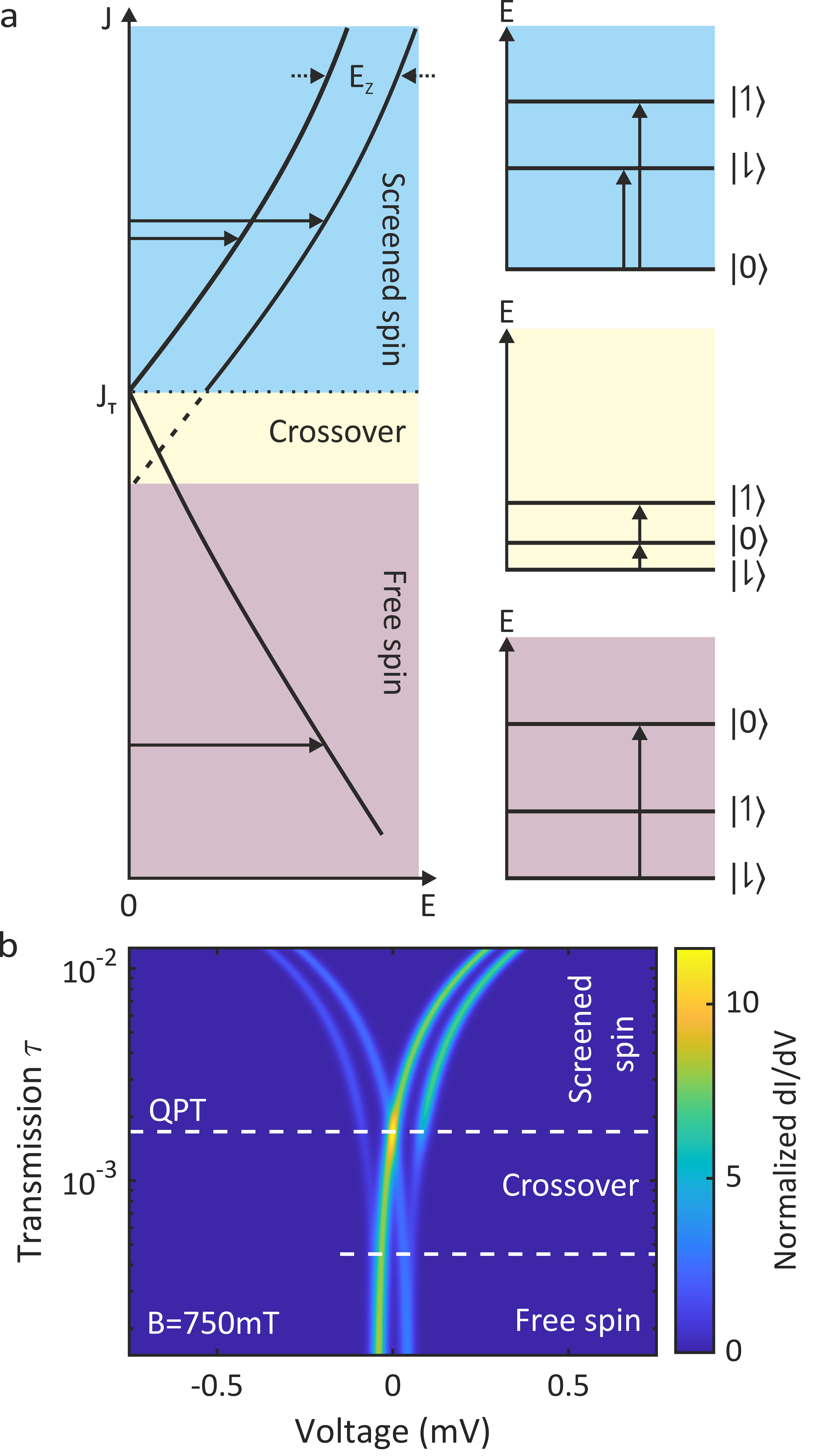
In addition to these two regimes, we found a crossover regime, where the two outer spectral features extend into the free spin regime, which is seen for both magnetic field values in Fig. 2(b) and (c). Due to the higher magnetic field in Fig. 2(b) than in (c), the crossover regime is also wider. The crossover regime marks a small region, where the excitation energy of the YSR state is smaller than the Zeeman splitting (). The outer spectral feature (marked by the arrow in Fig. 2(b)) in the crossover regime is a combination of quasiparticle tunneling from the thermally excited YSR state, which becomes exponentially suppressed as the YSR energy increases, and two-electron tunneling processes, i.e. resonant Andreev processes (see below and Supplementary Information sin ).
The different regimes for a spin- impurity are schematically displayed in Fig. 3(a). The screened spin regime (blue shade), where the exchange coupling is strong , features an ground state and a Zeeman split excited state. Two transitions are possible ( and ) as shown on the right blue panel. Lowering the exchange coupling, the state becomes the ground state at the QPT (). Interestingly, in the crossover regime the excited state is energetically between the ground state and the Zeeman split state . Therefore, both thermally excited tunneling and two-electron tunneling processes are possible resulting in the outer spectral feature (white arrow in Fig. 2(b)). As a consequence, two transitions can be observed ( and ). Further reducing the exchange coupling into the free spin regime reduces the visible transitions to one (), because the Zeeman split state cannot be thermally excited at 10 mK. We can reproduce the experimental findings theoretically by calculating a tunneling current from a master equation involving both single electron and two electron processes (for details see the Supplementary Information sin ). The calculation in Fig. 3(b) has been done for a magnetic field of 750 mT comparable to the experimental data in Fig. 2(b). All the features that we observed experimentally are reproduced in the calculations.
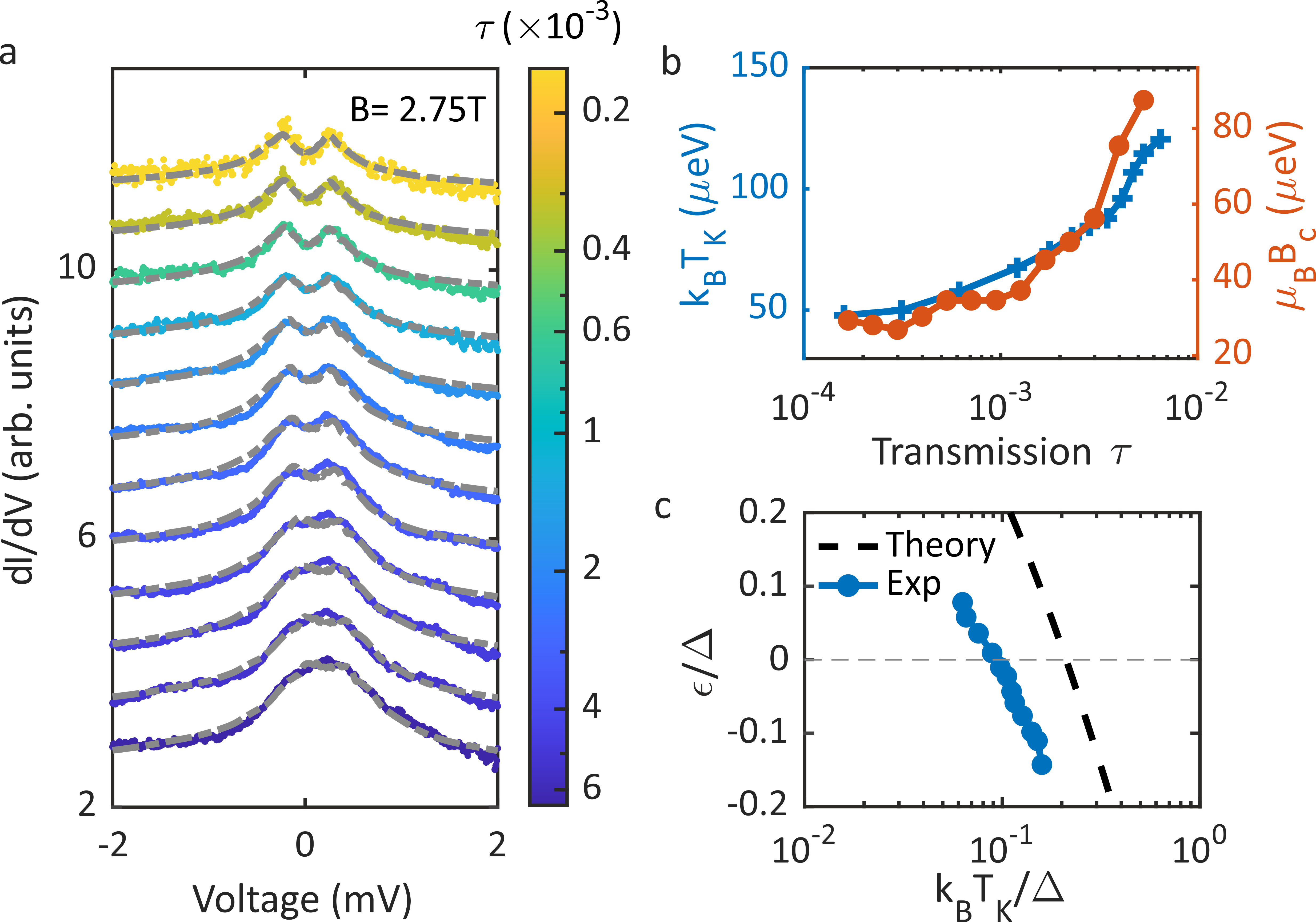
In order to independently verify the evolution of the YSR state through the QPT, we take a closer look at the YSR peak height and the resulting Kondo effect in the normal conducting state. The evolution of the YSR peak height is plotted in Fig. 2(d) in blue for the left and right peak as function of junction transmission. In the same graph the YSR peak energy is shown in orange. At the QPT (vertical dashed line), the YSR energy is zero and the peak height reverses indicating the QPT. This reversal is observable so clearly because resonant Andreev processes have not yet become significant. Further, we increase the magnetic field to 2.75 T such that both tip and sample become normal conducting and a Kondo peak appears Kondo (1964); Li et al. (1998); Madhavan et al. (1998); Ternes et al. (2008b). This is shown in Fig. 4(a), where the Kondo peak around zero bias voltage is displayed as a function of the junction transmission . We already see that the splitting of the Kondo peak in the magnetic field decreases as the transmission increases, which indicates that the Kondo temperature increases with increasing transmission. The higher Kondo temperature implies a stronger screening, which means that the Kondo peak starts splitting at a higher critical magnetic field . We have fitted the Kondo spectra using numerical renormalization group (NRG) theory Huang et al. (2022). This allows us to directly determine the Kondo temperature from the microscopic parameters extracted from the fit. The extracted Kondo temperature is shown in Fig. 4(b) as the blue line. It monotonously increases with increasing junction transmission , which corroborates the previous finding that the exchange coupling increases with increasing transmission (cf. Fig. 2(b) and (c)) Huang et al. (2020a); Cuevas et al. (1998). We also extracted the critical field , where the Kondo peaks starts splitting, as a function of transmission. The values for the critical field are plotted in Fig. 4(b) as a red line. The critical field increases with increasing transmission and follows the Kondo temperature very well. This corroborates very well the increase in impurity-substrate coupling for an increasing junction transmission. We further find a relation of between the Kondo temperature and the critical field with , which compares well with what has been found in the literature Hewson et al. (2005); Žitko et al. (2009); Kretinin et al. (2011).
Furthermore, scaling the Kondo temperature and the YSR energy to the superconducting gap , we compare the evolution across the QPT to the universal behavior predicted by NRG theory Satori et al. (1992); Yoshioka and Ohashi (2000); Bulla et al. (2008). The blue data points in Fig. 4(c) show the evolution of the YSR state across the QPT as function of the scaled Kondo temperature, which follows the predicted universal scaling (dashed line) with a slight offset. This deviation of the data from the universal curve is presumably due to subtle changes in the impurity-substrate coupling as a result of modifications in the atomic forces acting in the junction with and without the applied magnetic field. We, therefore, find a consistent picture for the behavior of the YSR state in a magnetic field across the quantum phase transition.
The evolution of the YSR state splitting across the QPT clearly demonstrates the change in the YSR ground state. For a spin- system, the nature of the ground state can be straightforwardly identified simply by the number of peaks in the spectrum. For higher order spins, the situation remains simple as long as the system can be assumed to be magnetically isotropic Machida et al. (2022). If the system experiences a magnetic anisotropy, the analysis of the YSR states becomes more cumbersome Žitko et al. (2011); von Oppen and Franke (2021). Still, the evolution in a magnetic field as well as with changing impurity-superconductor coupling (if susceptible to the atomic forces of the tip) greatly facilitates the identification of the ground state maybe even the spin state itself.
In summary, we present the evolution of a spin- impurity derived YSR state in a magnetic field across the QPT. Due to the extremely low temperature of the STM, the change from a single feature spectrum (free spin regime) to a double feature spectrum (screened spin regime) is clearly visible. This allows for an unambiguous determination of the ground state of the YSR state.
I Acknowledgments
The authors thank Carlos Cuevas and Andrea Hofmann for fruitful discussions. This study was funded in part by the ERC Consolidator Grant AbsoluteSpin (Grant No. 681164). JA and CP gratefully acknowledge financial support by the IQST and the BMBF through QSens (project QComp).
II Methods
The V(100) single crystal was sputtered (with Ar+), annealed to about 925 K, and cooled to ambient temperature repeatedly in ultra-high vacuum, ensuring an atomically flat sample surface. Typical surface reconstructions form with oxygen diffused from the bulk Koller et al. (2001); Kralj et al. (2003); Huang et al. (2020b). A small fraction of these defects exhibit YSR states Huang et al. (2020b). Similarly, we produce YSR states at the vanadium tip apex by repeatedly dipping the tip in situ into the substrateKaran et al. (2022); Huang et al. (2020b), which is verified in the conductance spectrum. This gives us full control to reproducibly design and define the junctions under investigation. We choose to use YSR functionalized tips for our experiments as they offered the flexibility to single out those fulfilling the required response to tip approach. Moreover, the YSR tips feature a range of YSR state energies and show a better junction stability at higher conductance than YSR states in the sample.
The experiments were performed in a low-temperature scanning tunneling microscope operating at 10 mK. Differential tunneling conductance () spectra were recorded using an open feedback loop with a standard lock-in technique (, 727.8 Hz). In Fig. 4(a) a modulation amplitude of was used. The tunneling current was measured through the tip with the voltage bias applied to the sample.
The calculations for the current based on the master equation are detailed in the Supplementary Information sin . For the Kondo spectra, we used the numerical renormalization group (NRG) theory in the framework of the single impurity Anderson model (SIAM) as implemented in “NRG Ljubljana” code Žitko and Pruschke (2009) to model the Kondo effect in a magnetic field. We fixed the Hubbard term to be much larger than the half bandwidth and modeled the asymmetry of the Kondo spectra using the intrinsic asymmetry parameter where is the impurity level Huang et al. (2022). The best agreement with the experiment corresponds to . The only free parameter left for fitting the Kondo spectra is the impurity-substrate coupling . The Kondo temperature was extracted from the fit through its definition with respect to the SIAM parameters Schrieffer and Wolff (1966); Yoshioka and Ohashi (2000); Kadlecová et al. (2019) , in which the effective bandwidth satisfies for and is a constant for Yoshioka and Ohashi (2000); Žitko (2007); Huang et al. (2022).
References
- Yu (1965) L. Yu, Bound state in superconductors with paramagnetic impurities, Acta Phys. Sin. 21, 75 (1965).
- Shiba (1968) H. Shiba, Classical spins in superconductors, Prog. Theor. Phys. 40, 435 (1968).
- Rusinov (1969) A. I. Rusinov, Superconductivity near a paramagmetic impurity, JETP Letters 9, 85 (1969).
- Yazdani et al. (1997) A. Yazdani, B. A. Jones, C. P. Lutz, M. F. Crommie, and D. M. Eigler, Probing the Local Effects of Magnetic Impurities on Superconductivity, Science 275, 1767 (1997).
- Balatsky et al. (2006) A. V. Balatsky, I. Vekhter, and J.-X. Zhu, Impurity-induced states in conventional and unconventional superconductors, Reviews of Modern Physics 78, 373 (2006).
- Heinrich et al. (2018) B. W. Heinrich, J. I. Pascual, and K. J. Franke, Single magnetic adsorbates on s-wave superconductors, Prog. Surf. Sci. 93, 1 (2018).
- Farinacci et al. (2018) L. Farinacci, G. Ahmadi, G. Reecht, M. Ruby, N. Bogdanoff, O. Peters, B. W. Heinrich, F. von Oppen, and K. J. Franke, Tuning the Coupling of an Individual Magnetic Impurity to a Superconductor: Quantum Phase Transition and Transport, Physical Review Letters 121, 196803 (2018).
- Küster et al. (2021) F. Küster, S. Brinker, S. Lounis, S. S. P. Parkin, and P. Sessi, Long range and highly tunable interaction between local spins coupled to a superconducting condensate, Nature Communications 12, 6722 (2021).
- Franke et al. (2011) K. J. Franke, G. Schulze, and J. I. Pascual, Competition of Superconducting Phenomena and Kondo Screening at the Nanoscale, Science 332, 940 (2011).
- Kamlapure et al. (2021) A. Kamlapure, L. Cornils, R. Žitko, M. Valentyuk, R. Mozara, S. Pradhan, J. Fransson, A. I. Lichtenstein, J. Wiebe, and R. Wiesendanger, Correlation of Yu–Shiba–Rusinov States and Kondo Resonances in Artificial Spin Arrays on an s-Wave Superconductor, Nano Letters 21, 6748 (2021).
- Malavolti et al. (2018) L. Malavolti, M. Briganti, M. Hänze, G. Serrano, I. Cimatti, G. McMurtrie, E. Otero, P. Ohresser, F. Totti, M. Mannini, R. Sessoli, and S. Loth, Tunable Spin–Superconductor Coupling of Spin 1/2 Vanadyl Phthalocyanine Molecules, Nano Letters 18, 7955 (2018).
- Bauer et al. (2013) J. Bauer, J. I. Pascual, and K. J. Franke, Microscopic resolution of the interplay of Kondo screening and superconducting pairing: Mn-phthalocyanine molecules adsorbed on superconducting Pb(111), Physical Review B 87, 075125 (2013).
- Chatzopoulos et al. (2021) D. Chatzopoulos, D. Cho, K. M. Bastiaans, G. O. Steffensen, D. Bouwmeester, A. Akbari, G. Gu, J. Paaske, B. M. Andersen, and M. P. Allan, Spatially dispersing Yu-Shiba-Rusinov states in the unconventional superconductor FeTe0.55Se0.45, Nature Communications 12, 298 (2021).
- Ruby et al. (2015) M. Ruby, F. Pientka, Y. Peng, F. von Oppen, B. W. Heinrich, and K. J. Franke, Tunneling Processes into Localized Subgap States in Superconductors, Phys. Rev. Lett. 115, 087001 (2015).
- Farinacci et al. (2020) L. Farinacci, G. Ahmadi, M. Ruby, G. Reecht, B. W. Heinrich, C. Czekelius, F. von Oppen, and K. J. Franke, Interfering Tunneling Paths through Magnetic Molecules on Superconductors: Asymmetries of Kondo and Yu-Shiba-Rusinov Resonances, Physical Review Letters 125, 256805 (2020).
- Brand et al. (2018) J. Brand, S. Gozdzik, N. Néel, J. L. Lado, J. Fernández-Rossier, and J. Kröger, Electron and Cooper-pair transport across a single magnetic molecule explored with a scanning tunneling microscope, Physical Review B 97, 195429 (2018).
- Kezilebieke et al. (2019) S. Kezilebieke, R. Žitko, M. Dvorak, T. Ojanen, and P. Liljeroth, Observation of Coexistence of Yu-Shiba-Rusinov States and Spin-Flip Excitations, Nano Letters 19, 4614 (2019).
- Huang et al. (2020a) H. Huang, R. Drost, J. Senkpiel, C. Padurariu, B. Kubala, A. L. Yeyati, J. C. Cuevas, J. Ankerhold, K. Kern, and C. R. Ast, Quantum phase transitions and the role of impurity-substrate hybridization in Yu-Shiba-Rusinov states, Communications Physics 3, 1 (2020a).
- Karan et al. (2022) S. Karan, H. Huang, C. Padurariu, B. Kubala, A. Theiler, A. M. Black-Schaffer, G. Morrás, A. L. Yeyati, J. C. Cuevas, J. Ankerhold, K. Kern, and C. R. Ast, Superconducting quantum interference at the atomic scale, Nature Physics 18, 893 (2022).
- Hatter et al. (2015) N. Hatter, B. W. Heinrich, M. Ruby, J. I. Pascual, and K. J. Franke, Magnetic anisotropy in Shiba bound states across a quantum phase transition, Nature Communications 6, 8988 (2015).
- Žitko et al. (2011) R. Žitko, O. Bodensiek, and T. Pruschke, Effects of magnetic anisotropy on the subgap excitations induced by quantum impurities in a superconducting host, Physical Review B 83, 054512 (2011).
- Cornils et al. (2017) L. Cornils, A. Kamlapure, L. Zhou, S. Pradhan, A. Khajetoorians, J. Fransson, J. Wiebe, and R. Wiesendanger, Spin-Resolved Spectroscopy of the Yu-Shiba-Rusinov States of Individual Atoms, Physical Review Letters 119, 197002 (2017).
- Schneider et al. (2021) L. Schneider, P. Beck, J. Wiebe, and R. Wiesendanger, Atomic-scale spin-polarization maps using functionalized superconducting probes, Science Advances 7, eabd7302 (2021).
- Machida et al. (2022) T. Machida, Y. Nagai, and T. Hanaguri, Zeeman effects on Yu-Shiba-Rusinov states, Physical Review Research 4, 033182 (2022).
- Lee et al. (2014) E. J. H. Lee, X. Jiang, M. Houzet, R. Aguado, C. M. Lieber, and S. De Franceschi, Spin-resolved Andreev levels and parity crossings in hybrid superconductor–semiconductor nanostructures, Nature Nanotechnology 9, 79 (2014).
- Huang et al. (2020b) H. Huang, C. Padurariu, J. Senkpiel, R. Drost, A. L. Yeyati, J. C. Cuevas, B. Kubala, J. Ankerhold, K. Kern, and C. R. Ast, Tunnelling dynamics between superconducting bound states at the atomic limit, Nature Physics 16, 1227 (2020b).
- Meservey et al. (1970) R. Meservey, P. M. Tedrow, and P. Fulde, Magnetic field splitting of the quasiparticle states in superconducting aluminum films, Physical Review Letters 25, 1270 (1970).
- Chen et al. (2008) Y. Chen, M. M. Doria, and F. M. Peeters, Vortices in a mesoscopic cone: A superconducting tip in the presence of an applied field, Physical Review B 77, 054511 (2008).
- Eltschka et al. (2014) M. Eltschka, B. Jäck, M. Assig, O. V. Kondrashov, M. A. Skvortsov, M. Etzkorn, C. R. Ast, and K. Kern, Probing absolute spin polarization at the nanoscale, Nano Lett. 14, 7171 (2014).
- Ternes et al. (2008a) M. Ternes, C. P. Lutz, C. F. Hirjibehedin, F. J. Giessibl, and A. J. Heinrich, The force needed to move an atom on a surface, Science 319, 1066 (2008a).
- Ternes et al. (2011) M. Ternes, C. González, C. P. Lutz, P. Hapala, F. J. Giessibl, P. Jelínek, and A. J. Heinrich, Interplay of conductance, force, and structural change in metallic point contacts, Physical Review Letters 106, 016802 (2011).
- Sakurai (1970) A. Sakurai, Comments on Superconductors with Magnetic Impurities, Progress of Theoretical Physics 44, 1472 (1970).
- (33) See Supplementary Information.
- Žitko and Pruschke (2009) R. Žitko and T. Pruschke, Energy resolution and discretization artifacts in the numerical renormalization group, Physical Review B 79, 085106 (2009).
- Kondo (1964) J. Kondo, Resistance Minimum in Dilute Magnetic Alloys, Progress of Theoretical Physics 32, 37 (1964).
- Li et al. (1998) J. Li, W.-D. Schneider, R. Berndt, and B. Delley, Kondo Scattering Observed at a Single Magnetic Impurity, Physical Review Letters 80, 2893 (1998).
- Madhavan et al. (1998) V. Madhavan, W. Chen, T. Jamneala, M. F. Crommie, and N. S. Wingreen, Tunneling into a Single Magnetic Atom: Spectroscopic Evidence of the Kondo Resonance, Science 280, 567 (1998).
- Ternes et al. (2008b) M. Ternes, A. J. Heinrich, and W.-D. Schneider, Spectroscopic manifestations of the Kondo effect on single adatoms, Journal of Physics: Condensed Matter 21, 053001 (2008b).
- Huang et al. (2022) H. Huang, S. Karan, C. Padurariu, B. Kubala, J. C. Cuevas, J. Ankerhold, K. Kern, and C. R. Ast, Universal scaling of tunable Yu-Shiba-Rusinov states across the quantum phase transition, arXiv:2212.11332 (2022).
- Cuevas et al. (1998) J. C. Cuevas, A. Levy Yeyati, A. Martín-Rodero, G. Rubio Bollinger, C. Untiedt, and N. Agraït, Evolution of Conducting Channels in Metallic Atomic Contacts under Elastic Deformation, Physical Review Letters 81, 2990 (1998).
- Hewson et al. (2005) A. C. Hewson, J. Bauer, and A. Oguri, Non-equilibrium differential conductance through a quantum dot in a magnetic field, Journal of Physics: Condensed Matter 17, 5413 (2005).
- Žitko et al. (2009) R. Žitko, R. Peters, and T. Pruschke, Splitting of the Kondo resonance in anisotropic magnetic impurities on surfaces, New J. Phys. 11, 053003 (2009).
- Kretinin et al. (2011) A. V. Kretinin, H. Shtrikman, D. Goldhaber-Gordon, M. Hanl, A. Weichselbaum, J. von Delft, T. Costi, and D. Mahalu, Spin-1/2 Kondo effect in an InAs nanowire quantum dot: Unitary limit, conductance scaling, and Zeeman splitting, Physical Review B 84, 245316 (2011).
- Satori et al. (1992) K. Satori, H. Shiba, O. Sakai, and Y. Shimizu, Numerical Renormalization Group Study of Magnetic Impurities in Superconductors, Journal of the Physical Society of Japan 61, 3239 (1992).
- Yoshioka and Ohashi (2000) T. Yoshioka and Y. Ohashi, Numerical Renormalization Group Studies on Single Impurity Anderson Model in Superconductivity: A Unified Treatment of Magnetic, Nonmagnetic Impurities, and Resonance Scattering, Journal of the Physical Society of Japan 69, 1812 (2000).
- Bulla et al. (2008) R. Bulla, T. A. Costi, and T. Pruschke, Numerical renormalization group method for quantum impurity systems, Reviews of Modern Physics 80, 395 (2008).
- von Oppen and Franke (2021) F. von Oppen and K. J. Franke, Yu-Shiba-Rusinov states in real metals, Physical Review B 103, 205424 (2021).
- Koller et al. (2001) R. Koller, W. Bergermayer, G. Kresse, E. L. D. Hebenstreit, C. Konvicka, M. Schmid, R. Podloucky, and P. Varga, The structure of the oxygen induced (1×5) reconstruction of V(100), Surface Science 480, 11 (2001).
- Kralj et al. (2003) M. Kralj, P. Pervan, M. Milun, K. Wandelt, D. Mandrino, and M. Jenko, HRAES, STM and ARUPS study of (5×1) reconstructed V(100), Surface Science 526, 166 (2003).
- Schrieffer and Wolff (1966) J. R. Schrieffer and P. A. Wolff, Relation between the Anderson and Kondo Hamiltonians, Physical Review 149, 491 (1966).
- Kadlecová et al. (2019) A. Kadlecová, M. Žonda, V. Pokornỳ, and T. Novotnỳ, Practical guide to quantum phase transitions in quantum-dot-based tunable Josephson junctions, Physical Review Applied 11, 044094 (2019).
- Žitko (2007) R. Žitko, Many-particle effects in resonant tunneling of electrons through nanostructures, Ph.D. thesis, University of Ljubljana, Ljubljana (2007).
Supplementary Material
III Theory: Introduction
A single spin- impurity gives rise to an in-gap Yu-Shiba-Rusinov state (YSR). Based on the occupation of the YSR state, the system wavefunction can be a spin doublet, when the YSR state is unoccupied, or a singlet, in the opposite case Anderson (1959); Žitko et al. (2011); Huang et al. (2020); Machida et al. (2022).
The presence of a magnetic field splits the doublet states. We denote by and the spin doublet states, that correspond to the free impurity spin. The states indicate that the spin- impurity is aligned, respectively anti-aligned, with the external magnetic field. The spin singlet, that corresponds to the screened impurity spin, is denoted by . The notation adopted here differs from the notation in the main text, by adding an emphasis on the occupation of the YSR state, that we believe is more intuitive for transport calculations. The notation in the main text for the doublet states and , indicating the total spin state, is equivalent to the notation here and , indicating an empty YSR state (free impurity spin) and the total spin. The notation in the main text for the singlet state , indicating the total spin , is equivalent here to the state , indicating the occupation of the YSR state.
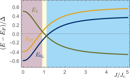
The energies of the three states , , and depend on the exchange coupling strength and give rise to three regimes, as shown in Fig. 3 of the main text. The free spin regime , a crossover regime , and the screened spin regime . We have assumed that , with the energy difference determined by the Zeeman splitting of the doublet state (as illustrated in Fig. S1).
For transport calculations, it is useful to work with fermionic excitation energies. We define the energy required to add a quasiparticle with spin to the YSR state as . We note that the state involved is , such that the impurity spin is screened by the added quasiparticle . Similarly, we denote by , the energy required to add a quasiparticle with spin to the YSR state. Consistent with our assumptions above, we have , therefore (as shown in Fig. S1).
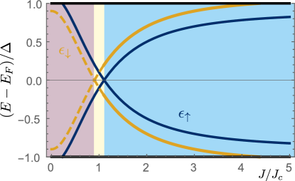
We note that it is possible to remove either a spin , or a spin quasiparticle from the YSR state, when it is in the singlet state . The implication therefore is that transport processes can result in the flip of the impurity spin, e.g. . Crucially, also the transport between the impurity and its host superconducting substrate can lead to such spin flip, as pointed out in Ref. van Gerven Oei et al. (2017).
III.1 Rate equations
The simplest theoretical framework that captures the transport properties of the Zeeman split states takes the form of a rate equation for the probabilities to be in one of three states, , , and . We denote by () the rate to remove a quasiparticle with spin () from the YSR state, and by () the rate to add a quasiparticle with spin () to the YSR state.
The rates represent a sum of all the contributing processes, intrinsic processes and tunneling processes, and depend on the bias voltage and the YSR state energy, that we parameterize by the exchange coupling strength (see Fig. S1).
The probabilities characterizing the three states obey the following rate equations,
| (S1) | ||||
| (S2) | ||||
| (S3) |
with the normalization condition .
The steady state probabilities are given by
| (S4) |
Where we have used the notation
In the following, we discuss the rates, which consist of intrinsic rates (, ) and tunneling rates (, ), with , such that
III.2 Intrinsic rates
The occupation of the YSR state can change due to intrinsic processes involving the quasiparticle population above the superconducting gap. We stress that these processes do not involve tunneling between the tip and substrate. The intrinsic process that describes the addition of a quasiparticle to the YSR state, changing the state from , with , to the singlet state , requires that the quasiparticle has spin , opposite to . We denote the corresponding rate by . Similarly, the rate to emit a quasiparticle with spin into the continuum, is denoted by . The latter process transforms the initial state into the doublet state .
In absence of tunneling between tip and substrate, the intrinsic processes in the tip and are responsible for the equilibrium value of the YSR state occupation. We apply detailed balance to determine the relations between the intrinsic rates. The equilibrium population in each state in absence of tunneling , , and , are obtained from Eqs. S4 by setting the tunneling rates to zero, such that and . We require that the equilibrium populations are related by the Fermi-Dirac distribution
Furthermore, we will assume that the rate to emit a quasiparticle with spin into the continuum, transition from to state , is independent of the orientation of the impurity spin . Therefore, we have
This assumption is not necessary, but convenient to reduce the number of parameters of the model. The physical mechanism behind such intrinsic processes, as well as the origin of the quasiparticle population above the gap at mK temperatures, remain unknown.
The two relations obtained by applying detailed balance, together with our assumption, express the intrinsic rates in terms of a single free parameter, which we denote , an intrinsic rate of relaxation. We parameterize the intrinsic rates in terms of , as follows
| (S5) | ||||
| (S6) | ||||
| (S7) |
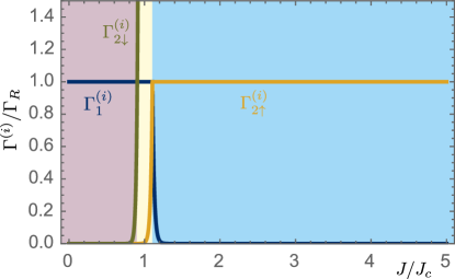
The intrinsic rates are shown in Fig. S2. The parametrization chose ensures that the intrinsic rates and are bound by . The intrinsic rate becomes much larger than in the regime , indicating that the higher excited state relaxes to the ground state in this regime at a rate much faster than the relaxation of the lower excited state .
III.3 Tunneling rates
We assume that the tunneling process is spin-conserving and characterized by a spin- and momentum-independent tunneling amplitude . The density of states of the substrate is denoted , that may differ for the two spin species . The chemical potentials for different spin species align and are denoted by for the substrate and for the tip, respectively. The occupation of the electronic states of the substrate is given by the Fermi-Dirac distribution .
In the experiment, the magnetic field is sufficiently large such that the substrate is in the normal-conducting state. This provides a simplification, since the density of states is approximately flat at the scale of the Zeeman splitting , and therefore becomes spin-independent. However, we will provide expressions for the rate equations that can account for a future experimental situation where the substrate density of states could be potentially spin-dependent.
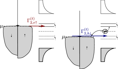
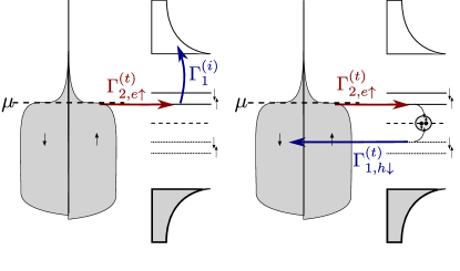
The rates describing tunneling processes contribute to the total rates and , as follows. When the initial state is either one of the doublets, , a tunneling process will add a quasiparticle with spin , opposite , resulting in the singlet. We distinguish two possibilities: either i. an electron with spin tunnels into the YSR state, with rate denoted by ; or ii. a hole with spin tunnels into the YSR state, with rate denoted by (see also Fig. S3). Since both processes create a quasiparticle excitation with spin in the YSR state, they add up to give the contribution to due to tunneling, denoted .
In the expressions above, we have introduced the coherence factors of the YSR state, and . We denoted by the probability to add an electron to the YSR state, while represents the probability to add a hole, respectively. Furthermore, we have used the convention that , where and are the chemical potentials of the substrate and tip, respectively. We have also introduced the common notation to denote the occupation for holes.
Similarly, we obtain the rates of tunneling processes that remove a quasiparticle from the YSR state, leading to the transition from state to one of the dublet states . A quasiparticle can be removed either by removing from the YSR state an electron with spin , , or a hole with spin , . We find in analogy to the results for adding a quasiparticle above,
III.4 Steady state current
The electrical current is expressed in terms of tunneling rates and the steady state probabilities. The latter are given by Eq. (S4), with the total rates and , given by sum of intrinsic and tunneling rates.
The total steady state current is given by the expression,
| (S8) |
The expression accounts for all charge transfer processes across the tip-substrate junction. The first term accounts for the possibility to add a quasiparticle to the YSR state either by transporting an electron with spin , or a hole with spin . The second term, similarly, accounts for the possibility to remove a quasiparticle with spin or from the YSR state , by transporting an electron with spin , or a hole with spin .
The total current can be further understood in terms of elementary transport processes. An elementary transport process consists of two transitions: the first changes the occupation of the YSR state, and the second restores the original occupation, thereby completing the transport cycle. We distinguish two types of elementary transport processes: i. when one transition occurs due to a tunneling process, while the other transition is intrinsic, such that a total charge is transported; and ii. when both transitions occur due to a tunneling process, such that a total charge is transported by sequential charge tunneling events. Fig. S4 illustrates an example of the two types of processes.
figurec
figurec
The total steady state current is the sum of currents contributed by the two types of processes,
III.4.1 Charge elementary transport process
For this transport process, charge is transported in a single tunneling event. We must account both for forward transport and for backward transport, as follows.
| (S9) |
The first term, proportional to , describes the process when an electron, or a hole, tunnels into the YSR state changing the occupation from to , as shown in Fig. S3. The second step of the elementary process occurs therefore via an intrinsic process, restoring an unoccupied YSR state , without charge transport. The total process is depicted in the left side of Fig. S4. Alternatively, the transition from to could occur by an intrinsic process, while the second step, from to , could occur by tunneling.
Note that the information about the energy of the states and filling factors of the substrate are all encoded in the rates and indirectly, in the steady state probabilities. Therefore, the expressions apply for all regimes, free spin, intermediate, as well as the screened spin regime.
III.4.2 Charge elementary transport process
When both steps of the elementary transport process involve a tunneling event, such as the process depicted in the right side of Fig. S4, the total transported charge is . The transport of charge is reminiscent of Andreev reflection. Indeed, the two charged particles involved in transport change the number of Cooper pairs in the tip condensate by one. However, there is also an important difference, the process described here is a sequential process consisting of two single particle transport events.
Elementary transport processes involving two sequential tunneling events have the following structure,
The combination of and describes an electron tunneling back and forth across the junction, giving rise to current noise, but without net charge transport. Similarly, the combination of and describes tunneling back and forth of a hole.
The transport of charge arises from combining tunneling of an electron into the tip with the subsequent tunneling of a hole out of the tip . Note that, as a consequence of the assumption in our model that tunneling can flip the spin of the impurity, all combinations are possible for the spin of the tunneling electron and hole.
While the process above transports a charge from the substrate to the tip, the reverse process is obtained by combining with , which transports a charge from the tip to the substrate.
The total resulting current is given by the sum over all possible processes
| (S10) |
We note that typically, only a few of the terms contribute significantly to the total current.
IV results
The experimentally relevant regime is defined by , corresponding to mT and a g-factor of , and . In this regime, the results reproduce the steps in current that arise when the voltage aligns the chemical potential of the substrate with an electronic transition of the tip YSR state (see Fig. S5). These current steps manifest as peaks in the differential conductance, as seen in Fig. S6.
In the free spin regime, a single peak is found in the differential conductance, corresponding to the electronic transition from the ground state to the singlet state . Transport processes starting in the higher energy spin state are thermally suppressed. In contrast, in the screened spin regime, two peaks are seen, contributed by transitions from the ground state to either excited states or . The distance between the two peaks is directly given by twice the Zeeman energy.
Both charge and charge elementary processes contribute significantly in the experimentally relevant parameter regime, although typically charge processes dominate.
The theoretical result presented in Fig. 3 of the main text, accounts for the fact that in the experiment, approaching the tip increases the transmission of the tunnel barrier, , and also modifies the effective exchange coupling , that leads to the modification of the YSR state excitation energies, and . We have used the simplest method to account for the simultaneous dependencies, by assuming a linear dependence of the YSR excitation energies on the transmission ,
| (S11) |
With this linear dependence, the result of the rate equation model reproduces well the measured data. The parameters and can be fitted independently, using the position of YSR peaks in absence of magnetic field. The only free parameters that concern electronic transport in presence of magnetic field are related to the intrinsic relaxation rate , the tunneling rate , and the asymmetry in the coherence factors of the YSR state, . These are fitting parameters for the plot in Fig. 3 in the main text.
References
- Anderson (1959) P. Anderson, Theory of dirty superconductors, Journal of Physics and Chemistry of Solids 11, 26 (1959).
- Žitko et al. (2011) R. Žitko, O. Bodensiek, and T. Pruschke, Effects of magnetic anisotropy on the subgap excitations induced by quantum impurities in a superconducting host, Phys. Rev. B 83, 054512 (2011).
- Huang et al. (2020) H. Huang, R. Drost, J. Senkpiel, C. Padurariu, B. Kubala, A. L. Yeyati, J. C. Cuevas, J. Ankerhold, K. Kern, and C. R. Ast, Quantum phase transitions and the role of impurity-substrate hybridization in Yu-Shiba-Rusinov states, Communications Physics 3, 199 (2020).
- Machida et al. (2022) T. Machida, Y. Nagai, and T. Hanaguri, Zeeman effects on Yu-Shiba-Rusinov states, Phys. Rev. Res. 4, 033182 (2022).
- van Gerven Oei et al. (2017) W.-V. van Gerven Oei, D. Tanasković, and R. Žitko, Magnetic impurities in spin-split superconductors, Phys. Rev. B 95, 085115 (2017).