A Coherent LQG approach to Quantum Equalization

Rebbecca TY Thien, Shanon L. Vuglar and Ian R. Petersen This work was supported by the Australian Research Council under grant DP210101938. It was also supported by the Office of Naval Research Global under agreement number N62909-19-2129.Rebbecca TY Thien is with the School of Engineering, The Australian National University, Canberra ACT 2601, Australia rebbecca.thien@anu.edu.auShanon L. Vuglar is with the College of STEM and Health Professions, John Brown University, Siloam Springs AR 72761, United States of America shanonvuglar@gmail.comIan R. Petersen is with the School of Engineering, The Australian National University, Canberra ACT 2601, Australia i.r.petersen@gmail.com
Abstract

We propose a method to design a suboptimal, coherent quantum LQG controller to solve a quantum equalization problem. Our method involves reformulating the problem as a control problem and then designing a classical LQG controller and implementing it as a quantum system. Illustrative examples are included which demonstrate the algorithm for both active and passive systems, i.e., systems where the dynamics are described in terms of both position and momentum operators and systems with dynamics in terms of annihilation operators only.

I INTRODUCTION

Communication systems are necessary for transmitting information over long distances, however, this often results in degradation of the quality. The goal of equalization is to estimate the transmitted signal from the received signal, compensating for the effects of noise and distortion. This is typically done by designing a filter that maps the received signal to an estimate of the original signal [1].

Refer to caption
Figure 1: A quantum optical communication system consisting of two beam splitters acting as a channel and a filter, respectively.

In the case of quantum communication systems, the laws of quantum mechanics limits their capacity to transfer information. Hence, the problem of correcting distortions in quantum communication systems is complex compared to its classical counterpart [2]. This problem is called the quantum equalization problem [3], and is depicted in Figure (1).

Quantum linear systems are a class of quantum systems whose dynamics take the specific form of a set of linear quantum stochastic differential equations (QSDEs). Such systems are common to the area of quantum optics [4, 5], and [6]. In general, a set of linear QSDEs need not correspond to a physically meaningful quantum system. To represent a physical quantum system, they must satisfy additional constraints; this leads to the notion of a physically realizable quantum system. This is discussed in [7], [8], and [9], where the authors derive necessary and sufficient conditions for such systems.

The goal of feedback control of quantum systems is to achieve closed-loop properties, such as stability, robustness, and entanglement. Coherent quantum control is a type of feedback control in which the controller itself is also a quantum system. This type of control has attracted considerable interest in recent years, since the use of a quantum controller may lead to an improved performance of the system, ease of implementations, or both [10, 11], and [12].

In this work, we propose a novel approach to solving the equalization problem by converting it into a coherent Linear Quadratic Gaussian (LQG) problem. This approach has several advantages over existing methods [3], and it provides a simple and systematic way to solve the equalization problem for both passive and active systems. Using our proposed approach, we can design a controller (fulfilling the role of an equalization filter) that optimizes the performance of the communication system while minimizing the impact of noise and distortion. The main difference between our work and [3], is that we are using the coherent LQG control, while [3] uses a Hsubscript𝐻H_{\infty}-like methodology. It is not possible to do a direct comparison between Hsubscript𝐻H_{\infty} control methods and LQG control methods, since their performance indices are measuring different quantities [19].

The main contribution of this work is threefold. Firstly, we propose an algorithm that solves the equalization problem for a passive system. Secondly, we extend our approach to solve the equalization problem for an active system, which is an extension of existing methods that only work for passive systems. Lastly, we demonstrate the practical relevance of our proposed method by giving an application in a real-world scenario.

Our proposed approach adapts results from [8], [9], and [13]. By converting the equalization problem into a coherent LQG problem, we can then design filters that optimize the performance of communication systems while minimizing the impact of noise and distortion. The remainder of the paper proceeds as follows: in Section II and III, we describe the quantum linear system models under consideration and define the corresponding notion of physical realizability, respectively. The latter section also includes some relevant previous results. Then, we formulate our problem in Section IV and propose our algorithm in Section V. Examples are given in Section VI followed by a conclusion and future work in Section VII.

II Linear Quantum Systems

We consider both passive and active linear quantum systems. Here, passive means that the system is defined in terms of annihilation operators only, while active means that the system is defined in terms of annihilation and creation operators. For the active system, we use position and momentum operators for convenience, so that we can directly use the results of [13].

II-A Passive Quantum Systems

Passive quantum systems are a class of systems that can be described using non-commutative or quantum probability theory [18]. In particular, the systems under consideration are described in terms of complex annihilation operators satisfying the linear quantum stochastic differential equations (QSDEs)

da(t)=Fa(t)dt+Gdw(t);dy(t)=Ha(t)dt+Jdw(t)formulae-sequence𝑑𝑎𝑡𝐹𝑎𝑡𝑑𝑡𝐺𝑑𝑤𝑡𝑑𝑦𝑡𝐻𝑎𝑡𝑑𝑡𝐽𝑑𝑤𝑡\begin{split}da(t)&=Fa(t)dt+Gdw(t);\\ dy(t)&=Ha(t)dt+Jdw(t)\\ \end{split} (1)

where Fn×n𝐹superscript𝑛𝑛F\in\mathbb{C}^{n\times n}, Gn×nw𝐺superscript𝑛subscript𝑛𝑤G\in\mathbb{C}^{n\times n_{w}}, Hny×n𝐻superscriptsubscript𝑛𝑦𝑛H\in\mathbb{C}^{n_{y}\times n}, Jny×nw𝐽superscriptsubscript𝑛𝑦subscript𝑛𝑤J\in\mathbb{C}^{n_{y}\times n_{w}} (n𝑛n, nysubscript𝑛𝑦n_{y}, nwsubscript𝑛𝑤n_{w} are positive integers). Here a(t)𝑎𝑡a(t) ==[a1(t)an(t)]Tsuperscriptdelimited-[]subscript𝑎1𝑡subscript𝑎𝑛𝑡𝑇[a_{1}(t)\dots a_{n}(t)]^{T} is a vector of annihilation operators on an underlying Hilbert space [7, 19].

The quantity w𝑤w describes the input variables and is assumed to admit the decomposition

dw(t)=βw(t)dt+dw~(t)𝑑𝑤𝑡subscript𝛽𝑤𝑡𝑑𝑡𝑑~𝑤𝑡dw(t)=\beta_{w}(t)dt+d\tilde{w}(t)

where w~~𝑤\tilde{w} is the noise part of w(t)𝑤𝑡w(t) and βw(t)subscript𝛽𝑤𝑡\beta_{w}(t) is an adapted process [14, 15, 16].The noise w~(t)~𝑤𝑡\tilde{w}(t) is an operator-valued process with a vector of quantum Weiner processes with a quantum Ito table

dw~(t)dw~(t)=Fw~dt𝑑~𝑤𝑡𝑑superscript~𝑤𝑡subscript𝐹~𝑤𝑑𝑡d\tilde{w}(t)d\tilde{w}^{\dagger}(t)=F_{\tilde{w}}dt

where Fw~subscript𝐹~𝑤F_{\tilde{w}} is a nonnegative Hermitian matrix [14, 15], and [16]. Here, the notation \dagger represents the adjoint transpose of a vector of operators. It is also assumed that the following communitation relations hold ofr the noise components:

[dw~(t),dw~(t)]dw~(t)dw~(t)(dw~(t)dw~(t)T)T=Twdt𝑑~𝑤𝑡𝑑~𝑤superscript𝑡𝑑~𝑤𝑡𝑑~𝑤superscript𝑡superscript𝑑~𝑤𝑡𝑑~𝑤superscript𝑡𝑇𝑇subscript𝑇𝑤𝑑𝑡[d\tilde{w}(t),d\tilde{w}(t)^{\dagger}]\triangleq d\tilde{w}(t)d\tilde{w}(t)^{\dagger}-(d\tilde{w}(t)d\tilde{w}(t)^{T})^{T}=T_{w}dt

where Twsubscript𝑇𝑤T_{w} is a Hermitian commutation matrix.

II-B Active Quantum Systems

An active quantum system is a system where the dynamics are described in terms of annihilation and creation or position and momentum operators. It can be described by the following linear quantum stochastic differential equations (QSDEs) [7, 8, 14, 15], and [16]:

dx(t)=Ax(t)dt+Bdw(t);dy(t)=Cx(t)dt+Ddw(t)formulae-sequence𝑑𝑥𝑡𝐴𝑥𝑡𝑑𝑡𝐵𝑑𝑤𝑡𝑑𝑦𝑡𝐶𝑥𝑡𝑑𝑡𝐷𝑑𝑤𝑡\begin{split}dx(t)&=Ax(t)dt+Bdw(t);\\ dy(t)&=Cx(t)dt+Ddw(t)\\ \end{split} (2)

where A,B,C𝐴𝐵𝐶A,B,C and D𝐷D are real matrices in n×nsuperscript𝑛𝑛\mathbb{R}^{n\times n}, n×nwsuperscript𝑛subscript𝑛𝑤\mathbb{R}^{n\times n_{w}}, ny×nsuperscriptsubscript𝑛𝑦𝑛\mathbb{R}^{n_{y}\times n} and ny×nwsuperscriptsubscript𝑛𝑦subscript𝑛𝑤\mathbb{R}^{n_{y}\times n_{w}} (n,nw,ny𝑛subscript𝑛𝑤subscript𝑛𝑦n,n_{w},n_{y} are even positive integers), respectively. Moreover, x(t)=[x1(t)xn(t)]𝑥𝑡delimited-[]subscript𝑥1𝑡subscript𝑥𝑛𝑡x(t)=[x_{1}(t)...x_{n}(t)] is a column vector of self-adjoint, possibly non-commutative, system variables.

Equations (2) must also preserve certain commutation relations as follows:

[xj(t),xk(t)]=xj(t)xk(t)xk(t)xj(t)=2iΘjksubscript𝑥𝑗𝑡subscript𝑥𝑘𝑡subscript𝑥𝑗𝑡subscript𝑥𝑘𝑡subscript𝑥𝑘𝑡subscript𝑥𝑗𝑡2𝑖subscriptΘ𝑗𝑘[x_{j}(t),x_{k}(t)]=x_{j}(t)x_{k}(t)-x_{k}(t)x_{j}(t)=2i\Theta_{jk} (3)

where ΘΘ\Theta is a real skew-symmetric matrix with components ΘjksubscriptΘ𝑗𝑘\Theta_{jk} where j,k=1,,nformulae-sequence𝑗𝑘1𝑛j,k=1,...,n and i=1𝑖1i=\sqrt{-1} in order to represent the dynamics of a physically meaningful quantum system.

The commutation relations (3) are said to be canonical if

Θm=diag(JΘ,JΘ,,JΘ)subscriptΘ𝑚diagsubscript𝐽Θsubscript𝐽Θsubscript𝐽Θ\Theta_{m}=\mathrm{diag}(J_{\Theta},J_{\Theta},...,J_{\Theta}) (4)

where JΘsubscript𝐽ΘJ_{\Theta} denotes the real skew-symmetric 2×2222\times 2 matrix

JΘ=[0110]subscript𝐽Θmatrix0110J_{\Theta}=\begin{bmatrix}0&1\\ -1&0\end{bmatrix}

and the “diagdiag\mathrm{diag}” notation indicates a block diagonal matrix assembled from the given entries. Here m𝑚m denotes the dimension of the matrix ΘmsubscriptΘ𝑚\Theta_{m}.

The vector quantity w𝑤w describes the input signals and is assumed to admit the decomposition

dw(t)=βw(t)dt+dw~(t)𝑑𝑤𝑡subscript𝛽𝑤𝑡𝑑𝑡𝑑~𝑤𝑡dw(t)=\beta_{w}(t)dt+d\tilde{w}(t)

where the self-adjoint, adapted process βw(t)subscript𝛽𝑤𝑡\beta_{w}(t) is the signal part of dw(t)𝑑𝑤𝑡dw(t) and dw~𝑑~𝑤d\tilde{w} is the noise part of dw(t)𝑑𝑤𝑡dw(t) [14, 15, 16].The noise w~(t)~𝑤𝑡\tilde{w}(t) is a vector of self-adjoint quantum noises with Ito table

dw~(t)dw~T(t)=Fw~dt𝑑~𝑤𝑡𝑑superscript~𝑤𝑇𝑡subscript𝐹~𝑤𝑑𝑡d\tilde{w}(t)d\tilde{w}^{T}(t)=F_{\tilde{w}}dt

where Fw~=Sw~+Tw~subscript𝐹~𝑤subscript𝑆~𝑤subscript𝑇~𝑤F_{\tilde{w}}=S_{\tilde{w}}+T_{\tilde{w}} is a nonnegative Hermitian matrix [16, 15] with Sw~subscript𝑆~𝑤S_{\tilde{w}} and Tw~subscript𝑇~𝑤T_{\tilde{w}} are real and imaginary, respectively. In this paper, we will assume Fw~subscript𝐹~𝑤F_{\tilde{w}} is of the form Fw~=I+iΘsubscript𝐹~𝑤𝐼𝑖ΘF_{\tilde{w}}=I+i\Theta where ΘΘ\Theta is of the form (4).

In this work, we consider a special case of (2):

dx(t)=Ax(t)dt+Budu(t)+Bvdv(t);dy(t)=Cx(t)dt+dv(t);formulae-sequence𝑑𝑥𝑡𝐴𝑥𝑡𝑑𝑡subscript𝐵𝑢𝑑𝑢𝑡subscript𝐵𝑣𝑑𝑣𝑡𝑑𝑦𝑡𝐶𝑥𝑡𝑑𝑡𝑑𝑣𝑡\begin{split}dx(t)&=Ax(t)dt+B_{u}du(t)+B_{v}dv(t);\\ dy(t)&=Cx(t)dt+dv(t);\\ \end{split} (5)

see also [7, 8, 13]. Here, dw(t)𝑑𝑤𝑡dw(t) from (2) has been partitioned into the signal input du(t)𝑑𝑢𝑡du(t) (a column vector with nusubscript𝑛𝑢n_{u} components) and the direct feed through quantum vacuum noise input dv(t)𝑑𝑣𝑡dv(t). We can regard such a quantum system as a coherent controller in a coherent quantum feedback control system; e.g., see [7, 8].

III Physical Realizability

III-A Passive Quantum Systems

In [20], the notion of physical realizability is developed based around the concept of a complex open quantum harmonic oscillator. We consider a passive quantum plant described by the following equations which are in terms of annihilation operators:

da(t)=Fa(t)dt+[G0G1G2][dv(t)Tdw(t)Tdu(t)T]T;dz(t)=H1a(t)dt+J12du(t);dy(t)=H2a(t)dt+[J20J210ny×ny][dv(t)Tdw(t)Tdu(t)T]Tformulae-sequence𝑑𝑎𝑡𝐹𝑎𝑡𝑑𝑡matrixsubscript𝐺0subscript𝐺1subscript𝐺2superscriptmatrix𝑑𝑣superscript𝑡𝑇𝑑𝑤superscript𝑡𝑇𝑑𝑢superscript𝑡𝑇𝑇formulae-sequence𝑑𝑧𝑡subscript𝐻1𝑎𝑡𝑑𝑡subscript𝐽12𝑑𝑢𝑡𝑑𝑦𝑡subscript𝐻2𝑎𝑡𝑑𝑡matrixsubscript𝐽20subscript𝐽21subscript0subscript𝑛𝑦subscript𝑛𝑦superscriptmatrix𝑑𝑣superscript𝑡𝑇𝑑𝑤superscript𝑡𝑇𝑑𝑢superscript𝑡𝑇𝑇\begin{split}da(t)&=Fa(t)dt+\begin{bmatrix}G_{0}&G_{1}&G_{2}\end{bmatrix}\\ &\begin{bmatrix}dv(t)^{T}&dw(t)^{T}&du(t)^{T}\end{bmatrix}^{T};\\ dz(t)&=H_{1}a(t)dt+J_{12}du(t);\\ dy(t)&=H_{2}a(t)dt+\begin{bmatrix}J_{20}&J_{21}&0_{n_{y}\times n_{y}}\end{bmatrix}\\ &\begin{bmatrix}dv(t)^{T}&dw(t)^{T}&du(t)^{T}\end{bmatrix}^{T}\end{split} (6)

where 𝔽n×n𝔽superscript𝑛𝑛\mathbb{F}\in\mathbb{C}^{n\times n}, 𝔾0n×nvsubscript𝔾0superscript𝑛subscript𝑛𝑣\mathbb{G}_{0}\in\mathbb{C}^{n\times n_{v}}, 𝔾1n×nwsubscript𝔾1superscript𝑛subscript𝑛𝑤\mathbb{G}_{1}\in\mathbb{C}^{n\times n_{w}}, 𝔾2n×nusubscript𝔾2superscript𝑛subscript𝑛𝑢\mathbb{G}_{2}\in\mathbb{C}^{n\times n_{u}}, 1nz×nwsubscript1superscriptsubscript𝑛𝑧subscript𝑛𝑤\mathbb{H}_{1}\in\mathbb{C}^{n_{z}\times n_{w}}, 𝕁12nz×nusubscript𝕁12superscriptsubscript𝑛𝑧subscript𝑛𝑢\mathbb{J}_{12}\in\mathbb{C}^{n_{z}\times n_{u}}, 2ny×nnsubscript2superscriptsubscript𝑛𝑦subscript𝑛𝑛\mathbb{H}_{2}\in\mathbb{C}^{n_{y}\times n_{n}}, 𝕁20ny×nvsubscript𝕁20superscriptsubscript𝑛𝑦subscript𝑛𝑣\mathbb{J}_{20}\in\mathbb{C}^{n_{y}\times n_{v}} and 𝕁21ny×nwsubscript𝕁21superscriptsubscript𝑛𝑦subscript𝑛𝑤\mathbb{J}_{21}\in\mathbb{C}^{n_{y}\times n_{w}}.

Similarly a controller is defined as follows:

dξ(t)=Fcξ(t)dt+[Gc0Gc1Gc][dwc0(t)dwc1(t)dy(t)]du(t)=Hcξ(t)dt+dwc0𝑑𝜉𝑡subscript𝐹𝑐𝜉𝑡𝑑𝑡matrixsubscript𝐺subscript𝑐0subscript𝐺subscript𝑐1subscript𝐺𝑐matrix𝑑subscript𝑤subscript𝑐0𝑡𝑑subscript𝑤subscript𝑐1𝑡𝑑𝑦𝑡𝑑𝑢𝑡subscript𝐻𝑐𝜉𝑡𝑑𝑡𝑑subscript𝑤subscript𝑐0\begin{split}d\xi(t)&=F_{c}\xi(t)dt+\begin{bmatrix}G_{c_{0}}&G_{c_{1}}&G_{c}\end{bmatrix}\begin{bmatrix}dw_{c_{0}}(t)\\ dw_{c_{1}}(t)\\ dy(t)\end{bmatrix}\\ du(t)&=H_{c}\xi(t)dt+dw_{c_{0}}\end{split} (7)

where ξ(t)=[ξ1(t)ξn(t)]T𝜉𝑡superscriptdelimited-[]subscript𝜉1𝑡subscript𝜉𝑛𝑡𝑇\xi(t)=[\xi_{1}(t)\ldots\xi_{n}(t)]^{T} is a vector of controller annihilation operator variables. We now define the notion of physically realizable for this class of systems.

Definition 1.

[9, Definition 3.1] The matrices Fcsubscript𝐹𝑐F_{c}, Gcsubscript𝐺𝑐G_{c}, Hcsubscript𝐻𝑐H_{c} are said to define a physically realizable controller of the form (7) if there exists matrices Gc0subscript𝐺subscript𝑐0G_{c_{0}}, Gc1subscript𝐺subscript𝑐1G_{c_{1}}, Hc1subscript𝐻subscript𝑐1H_{c_{1}} and Hc2subscript𝐻subscript𝑐2H_{c_{2}} such that the quantum system of the form (1)

dξ(t)=Fcξ(t)dt+[Gc0Gc1Gc][dwc0dwc1dy];[dudu1du2][HcHc1Hc2]ξ(t)dt+[I000I000I][dwc0dwc1dy]𝑑𝜉𝑡subscript𝐹𝑐𝜉𝑡𝑑𝑡matrixsubscript𝐺subscript𝑐0subscript𝐺subscript𝑐1subscript𝐺𝑐matrix𝑑subscript𝑤subscript𝑐0𝑑subscript𝑤subscript𝑐1𝑑𝑦matrix𝑑𝑢𝑑subscript𝑢1𝑑subscript𝑢2matrixsubscript𝐻𝑐subscript𝐻subscript𝑐1subscript𝐻subscript𝑐2𝜉𝑡𝑑𝑡matrix𝐼000𝐼000𝐼matrix𝑑subscript𝑤subscript𝑐0𝑑subscript𝑤subscript𝑐1𝑑𝑦\begin{split}d\xi(t)&=F_{c}\xi(t)dt+\begin{bmatrix}G_{c_{0}}&G_{c_{1}}&G_{c}\end{bmatrix}\begin{bmatrix}dw_{c_{0}}\\ dw_{c_{1}}\\ dy\end{bmatrix};\\ \begin{bmatrix}du\\ du_{1}\\ du_{2}\end{bmatrix}&\begin{bmatrix}H_{c}\\ H_{c_{1}}\\ H_{c_{2}}\end{bmatrix}\xi(t)dt+\begin{bmatrix}I&0&0\\ 0&I&0\\ 0&0&I\end{bmatrix}\begin{bmatrix}dw_{c_{0}}\\ dw_{c_{1}}\\ dy\end{bmatrix}\end{split} (8)

is physically realizable when Tysubscript𝑇𝑦T_{y} == J20TvJ20subscript𝐽20subscript𝑇𝑣superscriptsubscript𝐽20J_{20}T_{v}J_{20}^{\dagger} ++ J21TwJ21subscript𝐽21subscript𝑇𝑤superscriptsubscript𝐽21J_{21}T_{w}J_{21}^{\dagger} == I𝐼I.

Theorem 1.

[9, Theorem 3.2] Suppose the matrices Fcsubscript𝐹𝑐F_{c}, Gcsubscript𝐺𝑐G_{c}, and Hcsubscript𝐻𝑐H_{c} are such the corresponding system is minimal [20]. Then the matrices Fcsubscript𝐹𝑐F_{c}, Gcsubscript𝐺𝑐G_{c}, and Hcsubscript𝐻𝑐H_{c} define a physically realizable controller of the form (7) if and only if Fcsubscript𝐹𝑐F_{c} is Hurwitz and

Hc(sIFc)1Gc1subscriptnormsubscript𝐻𝑐superscript𝑠𝐼subscript𝐹𝑐1subscript𝐺𝑐1\|H_{c}(sI-F_{c})^{-1}G_{c}\|_{\infty}\leq 1

i.e., the corresponding system is bounded real [20]. In this case, the matrices Gc1subscript𝐺subscript𝑐1G_{c_{1}} and Hc1subscript𝐻subscript𝑐1H_{c_{1}} in (8) can be taken as zero.

III-B Active Quantum Systems

In [7], the notion of physical realizability is based on the concept of an open quantum harmonic oscillator. The following formally defines physical realizability for the more general case of active quantum systems.

Definition 2.

[7, Definition 3.1] The system (2) is said to be physically realizable if ΘΘ\Theta is canonical and there exists a quadratic Hamiltonian operator =(1/2)x(0)TRx(0)12𝑥superscript0𝑇𝑅𝑥0\mathcal{H}=(1/2)x(0)^{T}Rx(0), where R𝑅R is a real symmetric n×n𝑛𝑛n\times n matrix, and a coupling operator =Λx(0)Λ𝑥0\mathcal{L}=\Lambda x(0), where ΛΛ\Lambda is a complex-valued nw2×nsubscript𝑛𝑤2𝑛\frac{n_{w}}{2}\times n coupling matrix such that matrices A,B,C,𝐴𝐵𝐶A,B,C, and D𝐷D are given by

A𝐴\displaystyle A =2Θ(R+(ΛΛ))absent2Θ𝑅superscriptΛΛ\displaystyle=2\Theta(R+\Im{(\Lambda^{\dagger}\Lambda)}) (9a)
B𝐵\displaystyle B =2iΘ[ΛΛT]Γabsent2𝑖ΘsuperscriptΛsuperscriptΛ𝑇Γ\displaystyle=2i\Theta[-\Lambda^{\dagger}\quad\Lambda^{T}]\Gamma (9b)
C𝐶\displaystyle C =PT[Σny00Σny][Λ+Λ#iΛ+iΛ#]absentsuperscript𝑃𝑇matrixsubscriptΣsubscript𝑛𝑦00subscriptΣsubscript𝑛𝑦matrixΛsuperscriptΛ#𝑖Λ𝑖superscriptΛ#\displaystyle=P^{T}\begin{bmatrix}\Sigma_{n_{y}}&0\\ 0&\Sigma_{n_{y}}\end{bmatrix}\begin{bmatrix}\Lambda+\Lambda^{\#}\\ -i\Lambda+i\Lambda^{\#}\end{bmatrix} (9c)
D𝐷\displaystyle D =[Iny×ny0ny×(nwny)].absentsubscript𝐼subscript𝑛𝑦subscript𝑛𝑦subscript0subscript𝑛𝑦subscript𝑛𝑤subscript𝑛𝑦\displaystyle=[I_{n_{y}\times n_{y}}\quad 0_{n_{y}\times(n_{w}-n_{y})}]. (9d)

Here

Γ=PNwdiagNw(M);M=12[1i1i];ΣNy=[INy×Ny0Ny×(NwNy)];PNw(a1,a2,,a2Nw)T=(a1,,a2Nw1,a2,,a2Nw)T;formulae-sequenceΓsubscript𝑃subscript𝑁𝑤𝑑𝑖𝑎subscript𝑔subscript𝑁𝑤𝑀formulae-sequence𝑀12matrix1𝑖1𝑖formulae-sequencesubscriptΣsubscript𝑁𝑦subscript𝐼subscript𝑁𝑦subscript𝑁𝑦subscript0subscript𝑁𝑦subscript𝑁𝑤subscript𝑁𝑦subscript𝑃subscript𝑁𝑤superscriptsubscript𝑎1subscript𝑎2subscript𝑎2subscript𝑁𝑤𝑇superscriptsubscript𝑎1subscript𝑎2subscript𝑁𝑤1subscript𝑎2subscript𝑎2subscript𝑁𝑤𝑇\begin{split}\Gamma&=P_{N_{w}}diag_{N_{w}}(M);\\ M&=\frac{1}{2}\begin{bmatrix}1&i\\ 1&-i\end{bmatrix};\\ \Sigma_{N_{y}}&=[I_{N_{y}\times N_{y}}\quad 0_{N_{y}\times(N_{w}-N_{y})}];\\ P_{N_{w}}(a_{1},a_{2},...,a_{2N_{w}})^{T}&=(a_{1},...,a_{2N_{w}-1},a_{2},...,a_{2N_{w}})^{T};\end{split}

and diag(M)𝑀(M) is an appropriately dimensioned square block diagonal matrix with each diagonal block equal to the matrix M𝑀M. Note that the permutation matrix P𝑃P has the unitary property PPT=PTP=I𝑃superscript𝑃𝑇superscript𝑃𝑇𝑃𝐼PP^{T}=P^{T}P=I and Nw=nw/2subscript𝑁𝑤subscript𝑛𝑤2N_{w}=n_{w}/2 and Ny=ny/2subscript𝑁𝑦subscript𝑛𝑦2N_{y}=n_{y}/2.

The following theorem [7] gives necessary and sufficient conditions for the physical realizability of our system (5).

Theorem 2.

[7, Theorem 3.4] The system (5) is physically realizable if and only if

AΘn+ΘnAT+BvΘnvBvT+BuΘnuBuT=0;Bv[Iny×ny0(nwny)×ny]=ΘCTdiag(J);formulae-sequence𝐴subscriptΘ𝑛subscriptΘ𝑛superscript𝐴𝑇subscript𝐵𝑣subscriptΘsubscript𝑛𝑣superscriptsubscript𝐵𝑣𝑇subscript𝐵𝑢subscriptΘsubscript𝑛𝑢superscriptsubscript𝐵𝑢𝑇0subscript𝐵𝑣matrixsubscript𝐼subscript𝑛𝑦subscript𝑛𝑦subscript0subscript𝑛𝑤subscript𝑛𝑦subscript𝑛𝑦Θsuperscript𝐶𝑇𝑑𝑖𝑎𝑔𝐽\begin{split}A\Theta_{n}+\Theta_{n}A^{T}+B_{v}\Theta_{n_{v}}B_{v}^{T}+B_{u}\Theta_{n_{u}}B_{u}^{T}&=0;\\ B_{v}\begin{bmatrix}I_{n_{y}\times n_{y}}\\ 0_{(n_{w}-n_{y})\times n_{y}}\end{bmatrix}&=\Theta C^{T}diag(J);\end{split}

where Θn,ΘnvsubscriptΘ𝑛subscriptΘsubscript𝑛𝑣\Theta_{n},\Theta_{n_{v}} and ΘnusubscriptΘsubscript𝑛𝑢\Theta_{n_{u}} are all defined as in (4) but may be of different dimensions.

Here (.)(.)^{\dagger} denotes the complex conjugate transpose of a matrix while (.)#(.)^{\#} denotes the complex conjugate of a matrix.

In our work, we consider the Linear Matrix Inequality (LMI) version of the physical realizability which is similar to the approach in [7, 8] but reformulated into an LMI problem [13, Section 4].

IV Problem Formulation

The problem formulation described in this work is similar to [10, 8], with some minor differences. Suppose we have a quantum plant described by the following QSDEs which are a special case of (5):

dx(t)=Ax(t)dt+Bu^du^(t)+Bw1dw1(t);dy(t)=Cx(t)dt+Dw1dw1(t)formulae-sequence𝑑𝑥𝑡𝐴𝑥𝑡𝑑𝑡subscript𝐵^𝑢𝑑^𝑢𝑡subscript𝐵subscript𝑤1𝑑subscript𝑤1𝑡𝑑𝑦𝑡𝐶𝑥𝑡𝑑𝑡subscript𝐷subscript𝑤1𝑑subscript𝑤1𝑡\begin{split}dx(t)&=Ax(t)dt+B_{\hat{u}}d\hat{u}(t)+B_{w_{1}}dw_{1}(t);\\ dy(t)&=Cx(t)dt+D_{w_{1}}dw_{1}(t)\end{split} (10)

where the vector dw1𝑑subscript𝑤1dw_{1}==[dudw]Tsuperscript𝑑𝑢𝑑𝑤𝑇[du\quad dw]^{T}. This quantum plant (10) can be obtained through the combination of the dynamics of the quantum channel:

dx(t)=Ax(t)dt+Budu(t)+Bwdw(t);dy(t)=Cx(t)dt+Dudu(t)+Dwdw(t)formulae-sequence𝑑𝑥𝑡𝐴𝑥𝑡𝑑𝑡subscript𝐵𝑢𝑑𝑢𝑡subscript𝐵𝑤𝑑𝑤𝑡𝑑𝑦𝑡𝐶𝑥𝑡𝑑𝑡subscript𝐷𝑢𝑑𝑢𝑡subscript𝐷𝑤𝑑𝑤𝑡\begin{split}dx(t)&=Ax(t)dt+B_{u}du(t)+B_{w}dw(t);\\ dy(t)&=Cx(t)dt+D_{u}du(t)+D_{w}dw(t)\end{split}

and the low-pass filter:

dxf(t)=Afxf(t)dt+Bu^du^(t)+Budu(t);e¯(t)=xf(t)formulae-sequence𝑑subscript𝑥𝑓𝑡subscript𝐴𝑓subscript𝑥𝑓𝑡𝑑𝑡subscript𝐵^𝑢𝑑^𝑢𝑡subscript𝐵𝑢𝑑𝑢𝑡¯𝑒𝑡subscript𝑥𝑓𝑡\begin{split}dx_{f}(t)&=A_{f}x_{f}(t)dt+B_{\hat{u}}d\hat{u}(t)+B_{u}du(t);\\ \bar{e}(t)&=x_{f}(t)\end{split} (11)

as shown in Figure 1.

Also, suppose that we wish to minimize an infinite horizon quadratic cost function:

Jcost=limtf1tf0tfe¯(t)TR1e¯(t)+μu^(t)TR2u^(t))dt.J_{cost}=\lim_{t_{f}\to\infty}\frac{1}{t_{f}}\int_{0}^{t_{f}}\big{\langle}\bar{e}(t)^{T}R_{1}\bar{e}(t)+\mu\hat{u}(t)^{T}R_{2}\hat{u}(t))\big{\rangle}dt. (12)

The low pass filter (11) is introduced so that the cost function (12) will be well defined. This is justified since in practice, the equalization filter only needs to work over a finite bandwidth rather than an infinite bandwidth.

The problem is as follows: given a quantum plant of the form (10), design a classical LQG controller of the form

dx(t)=Akxk(t)dt+Bydy(t);du^(t)=Ckxk(t)dt.formulae-sequence𝑑𝑥𝑡subscript𝐴𝑘subscript𝑥𝑘𝑡𝑑𝑡subscript𝐵𝑦𝑑𝑦𝑡𝑑^𝑢𝑡subscript𝐶𝑘subscript𝑥𝑘𝑡𝑑𝑡\begin{split}dx(t)&=A_{k}x_{k}(t)dt+B_{y}dy(t);\\ d\hat{u}(t)&=C_{k}x_{k}(t)dt.\end{split} (13)

that minimizes the cost function (12), which then be implemented as a physically realizable LQG quantum controller of the form

dx(t)=Akxk(t)dt+Bydy(t)+Bv1dv1(t)+Bv2dv2(t);du^(t)=Ckxk(t)dt+dv1(t).formulae-sequence𝑑𝑥𝑡subscript𝐴𝑘subscript𝑥𝑘𝑡𝑑𝑡subscript𝐵𝑦𝑑𝑦𝑡subscript𝐵subscript𝑣1subscript𝑑subscript𝑣1𝑡subscript𝐵subscript𝑣2subscript𝑑subscript𝑣2𝑡𝑑^𝑢𝑡subscript𝐶𝑘subscript𝑥𝑘𝑡𝑑𝑡𝑑subscript𝑣1𝑡\begin{split}dx(t)&=A_{k}x_{k}(t)dt+B_{y}dy(t)+B_{v_{1}}d_{v_{1}}(t)+B_{v_{2}}d_{v_{2}}(t);\\ d\hat{u}(t)&=C_{k}x_{k}(t)dt+dv_{1}(t).\end{split} (14)

V Algorithm

The main idea of our algorithm is to design a classical LQG controller and then use the results in [9] (or [13]) to implement this controller as a physically realizable quantum system.

To begin with, we form a classical LQG problem. Consider the quantum plant (10) and the classical controller (13). This classical LQG problem can be solved in the usual manner [17, Theorem 5]. The solution is the controller (13) with

Ak=AKCBu^+KDu^F;By=K;Ck=F.formulae-sequencesubscript𝐴𝑘𝐴𝐾𝐶subscript𝐵^𝑢𝐾subscript𝐷^𝑢𝐹formulae-sequencesubscript𝐵𝑦𝐾subscript𝐶𝑘𝐹\begin{split}A_{k}&=A-KC-B_{\hat{u}}+KD_{\hat{u}}F;\\ B_{y}&=K;\\ C_{k}&=-F.\end{split}

The matrices F𝐹F and K𝐾K can be obtained as follows:

F=R21Bu^TP𝐹superscriptsubscript𝑅21superscriptsubscript𝐵^𝑢𝑇𝑃F=R_{2}^{-1}B_{\hat{u}}^{T}P

where P0𝑃0P\geq 0 is the solution to the ARE:

ATP+PA+PBu^R21Bu^TP+R1=0,superscript𝐴𝑇𝑃𝑃𝐴𝑃subscript𝐵^𝑢superscriptsubscript𝑅21superscriptsubscript𝐵^𝑢𝑇𝑃subscript𝑅10A^{T}P+PA+PB_{\hat{u}}R_{2}^{-1}B_{\hat{u}}^{T}P+R_{1}=0,

and

K=(QCT+V12)V21𝐾𝑄superscript𝐶𝑇subscript𝑉12superscriptsubscript𝑉21K=(QC^{T}+V_{12})V_{2}^{-1}

where Q0𝑄0Q\geq 0 is the solution to the ARE:

(AV12V21C)Q+Q(AV12V21C)TQCTV21Q+V1V12V21V12T=0.𝐴subscript𝑉12superscriptsubscript𝑉21𝐶𝑄𝑄superscript𝐴subscript𝑉12superscriptsubscript𝑉21𝐶𝑇𝑄superscript𝐶𝑇superscriptsubscript𝑉21𝑄subscript𝑉1subscript𝑉12superscriptsubscript𝑉21superscriptsubscript𝑉12𝑇0(A-V_{12}V_{2}^{-1}C)Q+Q(A-V_{12}V_{2}^{-1}C)^{T}\\ -QC^{T}V_{2}^{-1}Q+V_{1}-V_{12}V_{2}^{-1}V_{12}^{T}=0.

Note that,

𝔼[BuBwDuDw][dudw][dudw]T[BuBwDuDw]T=[V1V12V12TV2]dt.𝔼matrixsubscript𝐵𝑢subscript𝐵𝑤subscript𝐷𝑢subscript𝐷𝑤matrix𝑑𝑢𝑑𝑤superscriptmatrix𝑑𝑢𝑑𝑤𝑇superscriptmatrixsubscript𝐵𝑢subscript𝐵𝑤subscript𝐷𝑢subscript𝐷𝑤𝑇matrixsubscript𝑉1subscript𝑉12superscriptsubscript𝑉12𝑇subscript𝑉2𝑑𝑡\begin{split}\mathbb{E}&\begin{bmatrix}B_{u}&B_{w}\\ D_{u}&D_{w}\end{bmatrix}\begin{bmatrix}du\\ dw\end{bmatrix}\begin{bmatrix}du\\ dw\end{bmatrix}^{T}\begin{bmatrix}B_{u}&B_{w}\\ D_{u}&D_{w}\end{bmatrix}^{T}\\ &=\begin{bmatrix}V_{1}&V_{12}\\ V_{12}^{T}&V_{2}\end{bmatrix}dt.\end{split}

Next, we obtain a coherent LQG controller of the form (14) by applying the appropriate method from [13] or [9] based on the classical controller (13) with Aksubscript𝐴𝑘A_{k}, Bysubscript𝐵𝑦B_{y}, and Cksubscript𝐶𝑘C_{k} calculated above. To evaluate the cost (12) explicitly, we consider the closed loop system:

dζ(t)=Aclζ(t)dt+Bcldwcl(t);𝑑𝜁𝑡subscript𝐴𝑐𝑙𝜁𝑡𝑑𝑡subscript𝐵𝑐𝑙𝑑subscript𝑤𝑐𝑙𝑡d\zeta(t)=A_{cl}\zeta(t)dt+B_{cl}dw_{cl}(t); (15)

where

ζ=[xxk];wcl=[dw1dv1dv2]formulae-sequence𝜁matrix𝑥subscript𝑥𝑘subscript𝑤𝑐𝑙matrix𝑑subscript𝑤1𝑑subscript𝑣1𝑑subscript𝑣2\zeta=\begin{bmatrix}x\\ x_{k}\end{bmatrix};\quad w_{cl}=\begin{bmatrix}dw_{1}\\ dv_{1}\\ dv_{2}\end{bmatrix}

and

Jcl=Tr(R¯Q¯)subscript𝐽𝑐𝑙𝑇𝑟¯𝑅¯𝑄J_{cl}=Tr(\bar{R}\bar{Q}) (16)

where Q¯¯𝑄\bar{Q} is the unique symmetric positive definite solution of the Lyapunov equation

AQ¯+Q¯AT+BBT=0;𝐴¯𝑄¯𝑄superscript𝐴𝑇𝐵superscript𝐵𝑇0A\bar{Q}+\bar{Q}A^{T}+BB^{T}=0;

and

R¯=[R100CkTR2Ck].¯𝑅matrixsubscript𝑅100superscriptsubscript𝐶𝑘𝑇subscript𝑅2subscript𝐶𝑘\bar{R}=\begin{bmatrix}R_{1}&0\\ 0&C_{k}^{T}R_{2}C_{k}\end{bmatrix}.

That is, the cost function (12) is evaluated using the expression (16).

Our proposed algorithm can be summarized as follows:

  1. 1.

    Beginning with matrices A𝐴A, Bu^subscript𝐵^𝑢B_{\hat{u}} and C𝐶C in (10), we design a classical LQG controller (13) using the standard approach [17, Theorem 5] and obtain Aksubscript𝐴𝑘A_{k}, Bysubscript𝐵𝑦B_{y} and Cksubscript𝐶𝑘C_{k}.

  2. 2.

    Implement (13) as a coherent quantum controller using Theorem 1 or [13, Section 4].

  3. 3.

    Form the closed loop system (15) and evaluate the cost function (16).

VI Example of an Equalization System

Refer to caption
Figure 2: Equalization of an optical cavity system

We now consider a modified example of an equalization system from [3], as shown in Figure 2. The channel consists of an optical cavity and two optical beam splitters. The following are the constants used

κ=5,k=0.4,m=1k2,Ω=10andτ=0.1.formulae-sequence𝜅5formulae-sequence𝑘0.4formulae-sequence𝑚1superscript𝑘2Ω10and𝜏0.1\kappa=5,\quad k=0.4,\quad m=\sqrt{1-k^{2}},\quad\Omega=10~{}\text{and}~{}\tau=0.1.

The constants are adapted from [3, Section 6.2]. We will consider both passive and active systems for the equalization filter Σ(s)Σ𝑠\Sigma(s) in subsections (VI-A) and (VI-B), respectively. We will then comment on their relative performance.
Refer to caption
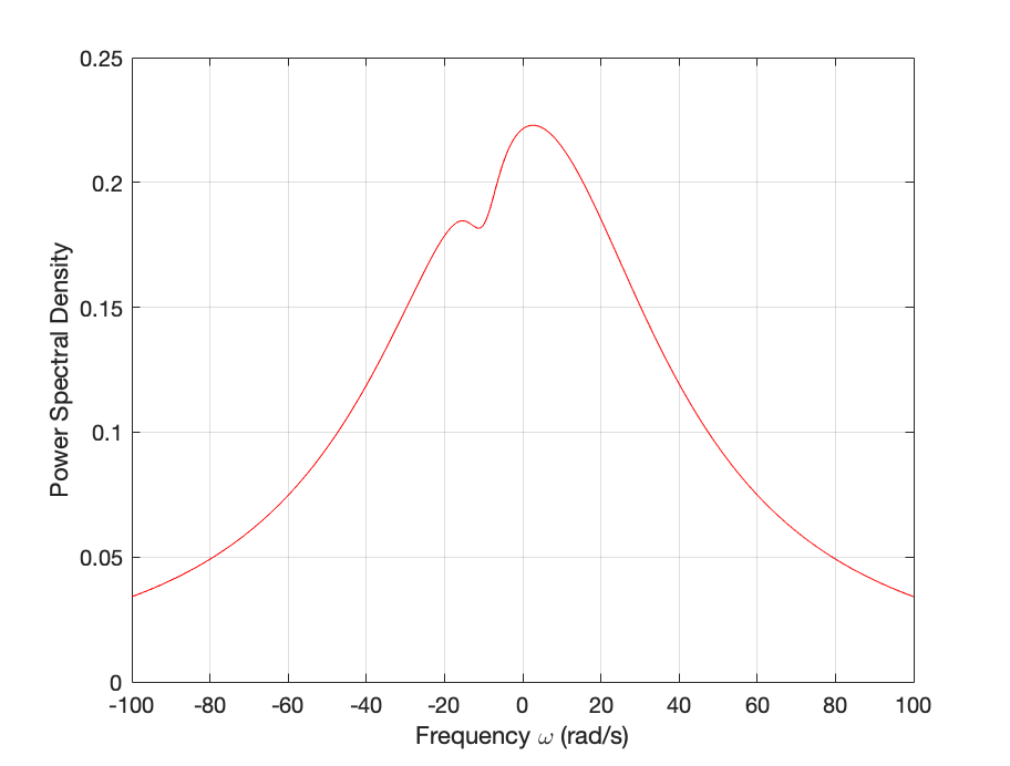
Figure 3: Closed loop Power Spectral Density for Passive Controller Design

VI-A Coherent LQG Control of a Passive Quantum System

Here our plant is of the form (5) with

A𝐴\displaystyle A =[k+iΩ001τ];absentmatrix𝑘𝑖Ω001𝜏\displaystyle=\begin{bmatrix}-k+i\Omega&0\\ 0&-\frac{1}{\tau}\end{bmatrix}; (17a)
Bu^subscript𝐵^𝑢\displaystyle B_{\hat{u}} =[01τ];absentmatrix01𝜏\displaystyle=\begin{bmatrix}0\\ \frac{1}{\tau}\end{bmatrix}; (17b)
Bw1subscript𝐵subscript𝑤1\displaystyle B_{w_{1}} =[k2κm2κ1τ0];absentmatrix𝑘2𝜅𝑚2𝜅1𝜏0\displaystyle=\begin{bmatrix}-k\sqrt{2\kappa}&-m\sqrt{2\kappa}\\ -\frac{1}{\tau}&0\end{bmatrix}; (17c)
C𝐶\displaystyle C =[k2κ0];absentmatrix𝑘2𝜅0\displaystyle=\begin{bmatrix}k\sqrt{2\kappa}&0\end{bmatrix}; (17d)
Dw1subscript𝐷subscript𝑤1\displaystyle D_{w_{1}} =[k2m22km]absentmatrixsuperscript𝑘2superscript𝑚22𝑘𝑚\displaystyle=\begin{bmatrix}k^{2}-m^{2}&2km\end{bmatrix} (17e)

and we choose R1subscript𝑅1R_{1}, R2subscript𝑅2R_{2}, μ𝜇\mu of (12) to be

R1=[0001];R2=1;μ=0.1.formulae-sequencesubscript𝑅1matrix0001formulae-sequencesubscript𝑅21𝜇0.1R_{1}=\begin{bmatrix}0&0\\ 0&1\end{bmatrix};\quad R_{2}=1;\quad\mu=0.1.

The evaluated cost function (16) is 18.0518.0518.05 and this is reflected in Figure 3 which gives the closed loop power spectral density of the quantity [R112e¯R212u^]matrixsuperscriptsubscript𝑅112¯𝑒superscriptsubscript𝑅212^𝑢\begin{bmatrix}R_{1}^{\frac{1}{2}}\bar{e}\\ R_{2}^{\frac{1}{2}}\hat{u}\end{bmatrix}.

Refer to caption
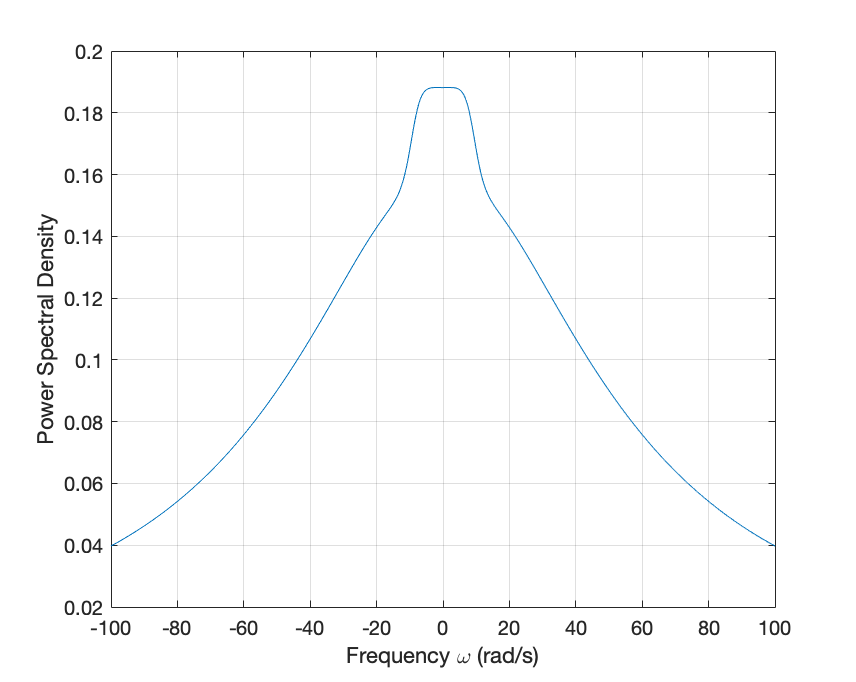
Figure 4: Closed loop Power Spectral Density for Active Controller Design

VI-B Coherent LQG Control of an Active Quantum System

For the active case, we use a similar plant as in equations (17a-17e) obtained by applying the conversion matrix [19, Equation 22]

Φ=[IIiIiI]Φmatrix𝐼𝐼𝑖𝐼𝑖𝐼\Phi=\begin{bmatrix}I&I\\ -iI&iI\end{bmatrix}

with appropriate dimensions to obtain matrices Agsubscript𝐴𝑔A_{g}, Bu^gsubscript𝐵subscript^𝑢𝑔B_{\hat{u}_{g}} and Cgsubscript𝐶𝑔C_{g} as follows:

Ag=ΦAΦ1;Bu^g=ΦBu^Φ1;Bw1g=ΦBw1Φ1;Cg=ΦCΦ1;Dw1g=ΦDw1Φ1formulae-sequencesubscript𝐴𝑔Φ𝐴superscriptΦ1formulae-sequencesubscript𝐵subscript^𝑢𝑔Φsubscript𝐵^𝑢superscriptΦ1formulae-sequencesubscript𝐵subscriptsubscript𝑤1𝑔Φsubscript𝐵subscript𝑤1superscriptΦ1formulae-sequencesubscript𝐶𝑔Φ𝐶superscriptΦ1subscript𝐷subscriptsubscript𝑤1𝑔Φsubscript𝐷subscript𝑤1superscriptΦ1\begin{split}A_{g}&=\Phi A\Phi^{-1};\\ B_{\hat{u}_{g}}&=\Phi B_{\hat{u}}\Phi^{-1};\\ B_{{w_{1}}_{g}}&=\Phi B_{w_{1}}\Phi^{-1};\\ C_{g}&=\Phi C\Phi^{-1};\\ D_{{w_{1}}_{g}}&=\Phi D_{w_{1}}\Phi^{-1}\end{split}

and R1subscript𝑅1R_{1}, R2subscript𝑅2R_{2}, μ𝜇\mu expands accordingly

R1=[02×202×202×2I2×2];R2=I2×2;μ=0.1.formulae-sequencesubscript𝑅1matrixsubscript022subscript022subscript022subscript𝐼22formulae-sequencesubscript𝑅2subscript𝐼22𝜇0.1R_{1}=\begin{bmatrix}0_{2\times 2}&0_{2\times 2}\\ 0_{2\times 2}&I_{2\times 2}\end{bmatrix};\quad R_{2}=I_{2\times 2};\quad\mu=0.1.

Now, the evaluated cost function (16) is 16.1716.1716.17 and this is reflected in Figure 4 which gives the closed loop power spectral density of the quantity [R112e¯R212u^]matrixsuperscriptsubscript𝑅112¯𝑒superscriptsubscript𝑅212^𝑢\begin{bmatrix}R_{1}^{\frac{1}{2}}\bar{e}\\ R_{2}^{\frac{1}{2}}\hat{u}\end{bmatrix}.

Refer to caption
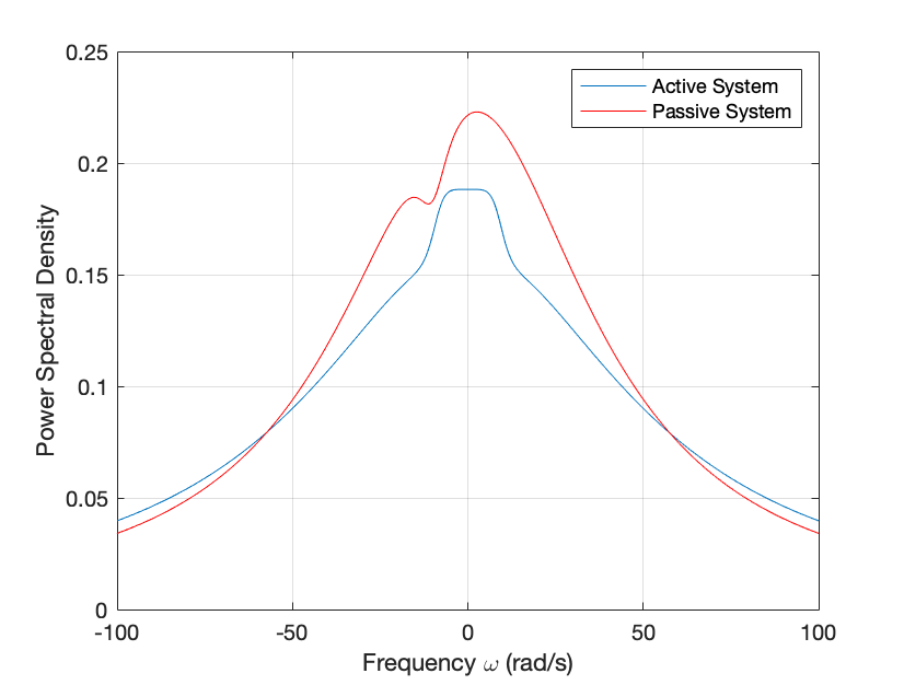
Figure 5: Closed loop Power Spectral Density for both Active and Passive Controller Designs

VI-C Comparison of controller system performance

The performance of the passive and active system’s cost function (16) is illustrated in Figure 5 in terms of the power spectral density graph. For this example, the active system gave only marginal improvement in comparison to the passive system. Note that this is consistent with the idea that the active system will perform at least as well as the passive system since the passive system is a special case of the active system.

VII CONCLUSION AND FUTURE WORK

VII-A Conclusion

The general idea of quantum equalization is to design a feedback controller that is a physically realizable quantum system and can compensate for the error in a quantum communication channel. In this work, we have proposed a method to find a physically realizable coherent LQG quantum controller that minimizes a cost function related to the system equalization error. Examples are shown for both passive and active linear quantum equalizers.

VII-B Future Work

In the example section, the active coherent filter performed only marginally better than the passive coherent filter. In a typical experimental setup, such marginal performance gain may or may not justify the additional complexity of an active coherent filter. Future work will explore experimental validation of this work.

References

  • [1] E. B. Gregory, ”Introduction,” in Channel Equalization for Wireless Communications: From Concepts to Detailed Mathematics: IEEE, 2011, pp. 1-29.
  • [2] V. Ugrinovskii and M. R. James, ”Wiener Filtering for Passive Linear Quantum Systems,” 2019: American Automatic Control Council, pp. 5372-5377.
  • [3] V. Ugrinovskii and M. James, ”Coherent Equalization of Linear Quantum Systems,” arXiv preprint arXiv:2211.06003, 2022.
  • [4] C. Gardiner and P. Zoller, Quantum Noise, Springer-Verlag Berlin Heidelberg; 2004.
  • [5] Hans‐A. Bachor and T. C. Ralph, A Guide to Experiments in Quantum Optics, Wiley-VCH; 2004.
  • [6] D.F. Walls and G. J. Milburn, Quantum Optics, Springer-Verlag Berlin Heidelberg; 2008.
  • [7] M. R. James, H. I. Nurdin, and I. R. Petersen, ”Hsuperscript𝐻H^{\infty} Control of Linear Quantum Stochastic Systems,” IEEE Transactions on Automatic Control, vol. 53, no. 8, pp. 1787-1803, 2008.
  • [8] S. L. Vuglar and I. R. Petersen, ”Quantum Noises, Physical Realizability and Coherent Quantum Feedback Control,” IEEE Transactions on Automatic Control, vol. 62, no. 2, pp. 998-1003, 2017.
  • [9] A. I. Maalouf and I. R. Petersen, ”Coherent Hsuperscript𝐻H^{\infty} Control for a Class of Annihilation Operator Linear Quantum Systems,” IEEE Transactions on Automatic Control, vol. 56, no. 2, pp. 309-319, 2011.
  • [10] H. I. Nurdin, M. R. James, and I. R. Petersen, ”Coherent quantum LQG control,” Automatica, vol. 45, no. 8, pp. 1837-1846, 2009.
  • [11] C. Xiang, I. R. Petersen, and D. Dong, ”Guaranteed cost coherent control for quantum systems with non-quadratic perturbations in the system Hamiltonian,” Automatica, vol. 139, p. 110201.
  • [12] D. Dong and I. R. Petersen, ”Quantum estimation, control and learning: Opportunities and challenges,” Annual Reviews in Control, vol. 54, pp. 243-251.
  • [13] R. T. Y. Thien, S. L. Vuglar, and I. R. Petersen, ”Optimal Quantum Realization of a Classical Linear System,” IFAC-PapersOnLine, vol. 53, no. 2, pp. 257-262, 2020/01/01/ 2020.
  • [14] R. L. Hudson and K.R. Parthasarathy, Quantum Ito’s formula and stochastic evolutions, Communications in Mathematical Physics, vol. 93, 1984, pp 301-323.
  • [15] K.R. Parthasarathy, An Introduction to Quantum Stochastic Calculus, Birkhäuser Basel; 1992.
  • [16] V. P. Belavkin, Quantum continual measurements and a posteriori collapse on CCR, Communications in Mathematical Physics, vol. 146, 1992, pp 611-631.
  • [17] H. Kwakernaak and R. Sivan, Linear Optimal Control Systems, Wiley Interscience; 1972.
  • [18] L. Bouten, R. Van Handel, and M. R. James, ”An Introduction to Quantum Filtering,” SIAM Journal on Control and Optimization, vol. 46, no. 6, pp. 2199-2241, 2007.
  • [19] I. R. Petersen, ”Quantum Linear Systems Theory,” The Open Automation and Control Systems Journal, vol. 8, pp. 67-93, 2016.
  • [20] A. I. Maalouf and I. R. Petersen, ”Bounded Real Properties for a Class of Annihilation-Operator Linear Quantum Systems,” IEEE Transactions on Automatic Control, vol. 56, no. 4, pp. 786-801, 2011