Automated robotic intraoperative ultrasound for brain surgery
I Introduction
During brain tumour resection, localising cancerous tissue and delineating healthy and pathological borders is challenging, even for experienced neurosurgeons and neuroradiologists [1]. Intraoperative imaging is commonly employed for determining and updating surgical plans in the operating room. Ultrasound (US) has presented itself a suitable tool for this task, owing to its ease of integration into the operating room and surgical procedure. However, widespread establishment of this tool has been limited because of the difficulty of anatomy localisation and data interpretation.
Publications on various applications of robotic US scanning have been produced in recent years. Robotic ultrasound scanning of the spine is a well-posed tracking task. [2] uses a semantic segmentation network to segment the spine, and in conjunction with a depth map, generates a robotic trajectory. [3] presents an automated method for lung diagnosis, using a pose estimation network to identify regions on the chest for path defining. [4] uses image quality optimization and interaction force adjustment to optimize probe pose and surface coupling.
In this work, we present a robotic framework designed and tested on a soft-tissue-mimicking brain phantom, simulating intraoperative US (iUS) scanning during brain tumour surgery. Our work builds on what was introduced in [5, 6].
II Methods
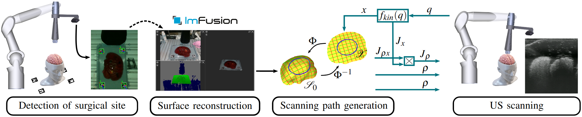
The workflow of our robotic iUS tissue scanning platform is depicted in Fig. 2.
II-A Soft-Tissue-Mimicking Brain Phantoms
A custom-made soft-tissue mimicking phantoms was made using GELITA® GELATINE Type Ballistic 3 with a brain-like silicone mold. To mimic soft tissue and extend the durability of the phantom, the phantom contained water:glycerine:gelatine at 45:45:10 wt.%. Inspired by [7], different objects were placed inside the phantom, including: olives, grapes, blueberries, screws. This ensures the presence of random features within the US recordings of the phantom.
II-B Localisation and Surface Reconstruction
For localisation, four ArUco markers are first manually placed around the area. Then the camera is positioned above the area of interest, such that all markers are visible within the image. This is enough to initialise the automatic localisation and reconstruction routine. Using the OpenCV [8] ArUco library, the four fiducial markers can be identified. Using these points, a plane - defined by a centre point and normal vector - containing the phantom is calculated. Using the detected plane, the robot automatically aligns the camera such that it’s z-axis points towards the plane’s centre at an angle of 45°and a distance of 30 cm. Using the RGB-D reconstruction algorithm - from the ImFusion Suite software solution by ImFusion GmbH - and executing a simple rotational trajectory - rotating the camera around the normal of the identified plane - a triangle mesh of the tissue phantom is extracted.
II-C Impedance-Controlled US Scanning
We use the impedance controller introduced in [9]. Surface-specific coordinates are defined on the surface mesh. These coordinates are the distance between transducer and surface, and the three orientation coordinates that align the probe axis and surface normal. Two additional coordinates control the position of the transducer on the surface. We stack all coordinates in a vector (cmp. Fig. 2) and implement the unified impedance control framework by [10]
| (1) |
Here, represent the symmetric, positive-definite stiffness and damping matrices, respectively. are the generalized configuration coordinates of the robot, () are the desired position and velocity in the coordinates, represents the Jacobian matrix mapping joint velocities to velocities . Controlling the distance results in passive interaction forces between US transducer and tissue, that depend on controller and object stiffnesses.
III Results
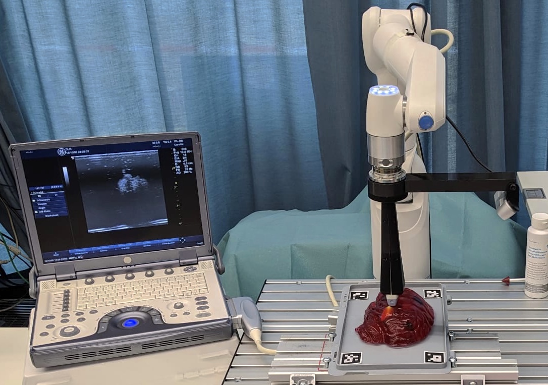
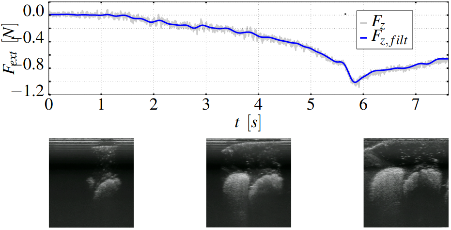
The experimental setup can be seen in Fig. 1. A seven degrees of freedom (DoF) DLR Miro surgical robotic arm is used. Attached is an Intel® RealSense™ Depth Camera D435i, and a GE 12L-RS linear US probe. The US transducer is connected to a GE LOGIQ e US machine. An ATI Mini45 F/T-sensor measures six DoF interaction forces during scanning. Results of the marker detection and surface 3D reconstruction can be seen in Fig. 2. Fig. 3 shows the interaction force between the US probe and phantom. The US probe was aligned normal to the surface (). The setpoint for the distance coordinate () was continuously decreased (increasing penetration depth) and held constant at a manually chosen value based on qualitative US image quality. The example US images were recorded during the experiment and show different stages of contact establishment - ranging from very little contact on the left to good probe-tissue coupling on the right. By controlling the distance, rather than the force, safe coupling of probe and surface can be achieved - invariant to tissue properties and geometry.
IV Conclusion
This work presents a framework for automated robotic iUS brain scanning. Where testing on a complex custom-made brain phantom shows that site localisation and surface reconstruction can be achieved and enables probe servoing with low interaction force. Future work will concern visual servoing for probe pose and US quality optimisation, while minimising required interaction forces.
References
- [1] L. Dixon, A. Lim, M. Grech-Sollars, D. Nandi, and S. J. Camp, “Intraoperative ultrasound in brain tumor surgery: A review and implementation guide,” Neurosurgical Review, vol. 45, pp. 2503 – 2515, 2022.
- [2] M. Victorova, M. K.-S. Lee, D. Navarro-Alarcon, and Y. P. Zheng, “Follow the curve: Robotic ultrasound navigation with learning based localization of spinous processes for scoliosis assessment,” IEEE Access, vol. PP, pp. 1–1, 2021.
- [3] X. Ma, Z. Zhang, and H. K. Zhang, “Autonomous scanning target localization for robotic lung ultrasound imaging,” 2021 IEEE/RSJ International Conference on Intelligent Robots and Systems (IROS), pp. 9467–9474, 2021.
- [4] Z. Jiang, M. Grimm, M. Zhou, Y. Hu, J. Esteban, and N. Navab, “Automatic force-based probe positioning for precise robotic ultrasound acquisition,” IEEE Transactions on Industrial Electronics, vol. 68, no. 11, pp. 11 200–11 211, 2021.
- [5] A. Weld, M. Dyck, J. Klodmann, G. Anichini, L. Dixon, S. J. Camp, A. Albu-Schäffer, and S. Giannarou, “Collaborative robotic ultrasound tissue scanning for surgical resection guidance in neurosurgery,” Proceedings of The 14th Hamlyn Symposium on Medical Robotics, vol. abs/2301.08174, 2022.
- [6] M. Dyck, A. Weld, J. Klodmann, A. Kirst, L. Dixon, G. Anichini, S. J. Camp, S. Giannarou, and A. Albu-Schäffer, “Collaborative robotic ultrasound tissue scanning for surgical resection guidance in neurosurgery,” IEEE Transactions on Medical Robotics and Bionics, 2022, submitted for publication.
- [7] H. Morehouse, H. P. Thaker, and C. Persaud, “Addition of metamucil to gelatin for a realistic breast biopsy phantom,” Journal of Ultrasound in Medicine, vol. 26, 2007.
- [8] Itseez, “Open source computer vision library,” https://github.com/itseez/opencv, 2015.
- [9] M. Dyck, A. Sachtler, J. Klodmann, and A. Albu-Schäffer, “Impedance control on arbitrary surfaces for ultrasound scanning using discrete differential geometry,” IEEE Robotics and Automation Letters, vol. 7, no. 3, pp. 7738–7746, 2022.
- [10] A. Albu-Schäffer, C. Ott, and G. Hirzinger, “A unified passivity-based control framework for position, torque and impedance control of flexible joint robots,” The international journal of robotics research, vol. 26, no. 1, pp. 23–39, 2007.