Autonomous Power Line Inspection with Drones
via Perception-Aware MPC
Abstract
Drones have the potential to revolutionize power line inspection by increasing productivity, reducing inspection time, improving data quality, and eliminating the risks for human operators. Current state-of-the-art systems for power line inspection have two shortcomings: (i) control is decoupled from perception and needs accurate information about the location of the power lines and masts; (ii) obstacle avoidance is decoupled from the power line tracking, which results in poor tracking in the vicinity of the power masts, and, consequently, in decreased data quality for visual inspection. In this work, we propose a model predictive controller (MPC) that overcomes these limitations by tightly coupling perception and action. Our controller generates commands that maximize the visibility of the power lines while, at the same time, safely avoiding the power masts. For power line detection, we propose a lightweight learning-based detector that is trained only on synthetic data and is able to transfer zero-shot to real-world power line images. We validate our system in simulation and real-world experiments on a mock-up power line infrastructure. We release our code and datasets to the public.
Supplementary Material
Video: https://youtu.be/JA6h-Nv29pU
I Introduction
Drones exhibit the potential to bring about a revolutionary transformation in the industrial inspection market [1, 2]. Particularly, quadrotors are a fast-to-deploy and cost-effective solution for power line inspection. The EU and US power systems consist of more than 10 million km of power lines and distribution transformers, which connect more than 400 million customers [3, 4]. The power line infrastructure needs to be inspected regularly to avoid power outages and natural disasters (California’s second-largest wildfire was sparked when power lines came in contact with a tree [5]).
Power line inspection requires teams of specialized human labor who use ad-hoc equipment, such as ropes and scaffoldings, to access the power line infrastructure and manned helicopters for long-range operations. These factors result in high expenses, significant dangers for human operators, and low productivity in the inspection operation. Quadrotors can cut the costs by [1] as a consequence of the increase of productivity, the reduction of the inspection time, the improvement of the data quality, and the elimination of the risks for the human operators [6].
Power line inspection with drones is still done by skilled pilots. The use of autonomous drones is still limited. Developing a fully autonomous solution is challenging because the drone needs to take decisions during the flight that are affected by conflicting goals: the drone needs to fly close to the power lines to maximize the data quality for visual inspection starting from a rough knowledge of the reference trajectory, and at the same time, it must avoid collisions with the power lines and masts, for which precise location information is unavailable.
State-of-the-art autonomous systems for power line inspection have two shortcomings: (i) Control and motion planning are separated from perception, and they also require precise information regarding the location of power lines and masts. This information is only available in limited cases. (ii) Collision avoidance and power line tracking are decoupled, which could lead to losing track of the power lines after successfully avoiding an obstacle. For further details, we refer the reader to a survey on autonomous, vision-based robotic inspection of power lines [7].
We propose a vision-based, tightly-coupled perception and action solution for autonomous power line inspection that does not require prior information about the power line infrastructure, such as the location of the power lines and masts. Our method plans and tracks a trajectory that maximizes the visibility of the power line in the onboard-camera view and, at the same time, can safely avoid obstacles such as the power masts. We achieve this by developing a perception-aware Model Predictive Controller (MPC) [8] that includes two perception objectives: one for line tracking and one for collision avoidance. Adding multiple, and possibly conflicting, perception objectives in the MPC is a challenging task. In particular, the optimization could become infeasible and computationally intractable on resource-constrained platforms such as quadrotors. We overcome this problem by letting the MPC optimize over the weights of the two perception objectives online.
To detect the power lines, we propose a novel perception module that extends the deep-learning–based object detector in [9] to the case of power line detection. The perception module is trained only on synthetic data and transfers zero-shot to real-world images of power lines without any fine-tuning. In this way, we overcome the problem of the limited amount of annotated data for supervised learning.
We demonstrate our system both on simulated data and on a physical quadrotor platform operating in a mock-up power-line infrastructure. We show that our approach is capable of accurately tracking the power lines and avoiding the power masts starting from a rough reference trajectory. We believe that our method will contribute to accelerating the deployment of autonomous drones for power line inspection. Our main contributions are:
-
•
A novel system that tightly couples perception and action for autonomous, vision-based power line inspection.
-
•
A model predictive controller that optimizes online the weight of the line tracking and collision avoidance objectives.
-
•
A learning-based power line detector that is trained only on synthetic data and transfers zero-shot to real-world images of power lines.
-
•
Thorough validation of the full system and all its building blocks both in simulation and in the real world on a mock-up power line infrastructure.
II Related Work
An overview of prior works in aerial power line inspection using drones is in [7]. Planning and control strategies are presented in [10, 11]. A PID controller to control the position and orientation of a quadrotor in relation to the power lines is proposed in [10]. The solution proposed in [11] uses perspective relation and estimation of the position of the next tower to guide the drone. Both works loosely couple perception, planning, and control and consequently either need to have access to an accurate reference trajectory or could result in poor line tracking after the collision avoidance maneuver. A number of works [12, 13, 14, 15, 16] focus on the perception task of detecting and tracking the power lines. Model-based approaches, such as variants of Hough transform and filters, using cameras are proposed in [12, 13, 14]. In spite of their high weight and computational load, Lidars could also be employed in some specific situations as proposed in [15]. Event camera [17] is a novel sensor that provides lower latency and higher dynamic range measurements than standard cameras. Combining events and standard frames can make robotic perception more robust against motion blur and low light conditions [18]. In [16], a solution is proposed to detect and track the power lines using event data.
Extensive literature exists on obstacle avoidance methods for quadrotor flights. However, state-of-the-art methods [19, 20] cannot directly be applied to the power line inspection problem because they neglect the objective of tracking visual points of interest, such as the power lines.
Model predictive control [21] is a powerful solution to couple planning and control for quadrotor autonomous flights. The benefits of MPC compared to other control strategies are analyzed in [22]. MPC has been used for perching on power lines [23] and agile flights [24]. The first work introducing perception awareness in MPC is [8] where the authors propose to include a perception objective in the MPC to keep a point of interest in the camera field of view. Our MPC controller is inspired by [8]. However, we deal with two different perception objectives, line tracking, and collision avoidance, which conflict with each other when the drone approaches the power masts. To enable collision avoidance capabilities, in [25], the authors utilized a chance-constrained MPC formulation. This probabilistic collision constraint allows to account for the perceptual uncertainty and consequently enhances the obstacle avoidance robustness. In [26], it is shown a real-world application of the chance-constrained MPC for dynamic obstacle avoidance. In [27], an MPC-based reactive planner for visual target tracking and obstacle avoidance is presented. Different from our method, this MPC does not directly generate control commands but planned trajectories, which are tracked by another low-level controller.
III Methodology
III-A Notation
In this manuscript, we define three reference frames. is the fixed world frame, whose axis is aligned with the gravity, is the quadrotor body frame, and is the camera frame. These reference frames are depicted in Fig. 1. We represent vectors and matrices as bold quantities. We use capital letters for matrices. Vectors have a suffix representing the frame in which they are expressed and their endpoint. For example, the quantity represents the position of the body frame with respect to the world frame . We use the symbol to denote the rotation matrix that rotates a vector from the frame to the frame . We use to denote the quaternion representation of this rotation. The time derivative of a vector is represented by . In the case of quaternion, the time derivative is defined as , where is the screw-symmetric matrix of the vector . The symbol represents the quaternion-vector product. The symbol represents the cross product between two vectors.
III-B Quadrotor Dynamics
Let , and be the position, orientation, and linear velocity of the quadrotor expressed in the world frame . Let be the angular velocity of the body expressed in the body frame . Additionally, let be the body collective thrust, where is the thrust produced by the i-th motor, be the collective thrust vector, be the mass of the quadrotor, and be the gravity vector. Finally, let be the diagonal moment of inertia matrix and the body collective torque. The quadrotor dynamical model is:
| (1) |
The body torque is represented by:
| (2) |
where , for = [1, 2, 3, 4] are the distances of each rotor to the body frame and is the rotor drag constant. The state and input vector of the system are and .
III-C MPC Formulation
The system dynamics in Eq. 1 can be written in compact form as . We compute the discrete-time version of it by using a Runge-Kutta method of 4th order with time step : . The MPC formulation is a non-linear program with quadratic costs:
| (3) | ||||
This is solved as a sequential quadratic program (SQP) executed in a real-time iteration scheme [28]. The values and refer to the difference with respect to the reference of each value. We implement this optimization problem in ACADO [29] and use the qpOASES solver [30].
III-D Perception Objectives
We include two perception objectives: one for line tracking and one for collision avoidance, in the MPC formulation proposed in Eq. 3.
Line Tracking: The purpose of this objective is to keep the power line in the center of the image (c.f. Fig. 2), to maximize data quality for visual inspection, and to keep a safe distance from the power lines. We derive the line tracking objective in this section by extending the perception objective proposed for a single point in [8]. We denote the position of the line endpoints in the world frame as . These points are transformed to the camera frame by:
| (4) |
The points: and are projected into the image plane coordinates: according to the classical pinhole camera model [31]. The cartesian coordinates are transformed into the polar coordinates as:
| (5) |
We introduce a new variable in our MPC formulation:
| (6) |
The variable represents the distance of the line to the body frame (c.f. Fig. 1) and represents the target value of . The value of is set by the user according to the desired distance of the flight from the power lines. Obstacle Avoidance: Inspired by [32, 26], we include collision avoidance capabilities in our MPC by means of a collision cost and a collision constraint. The collision cost is formulated with the logistic function:
| (7) |
where represents the norm of the distance of the body frame to the detected obstacle.
The values are constant quantities that represent weight, smoothness, and distance threshold, respectively.
The collision constraint is formulated as a probabilistic chance constraint to account for the uncertainty in the drone state and in the obstacle detection.
The objective of this constraint is to ensure that the probability of the collision with an obstacle is less than a predefined threshold: .
We model obstacles as ellipsoids.
Let be the semi-principal axes of the ellipsoid modeling an obstacle, and the radius of a safety area around the quadrotor body frame.
The quadrotor is considered to be in collision with the obstacle when:
| (8) |
where is the uncertainty matrix defined as . The quantity and represent the position and orientation of the obstacle with respect to the world frame . Assuming that the quadrotor and obstacle positions are random variables distributed according to Gaussian distributions: , and , respectively, we derive the deterministic form of the chance constraint as:
| (9) |
where is the normalized distance from the body frame to the obstacle and erf() is the standard error function for Gaussian distributions [33]. We rearrange Eq. III-D and write it using the shorthand hereafter.
III-E Perception-aware MPC for power line inspection
The two perception objectives of line tracking and obstacle avoidance conflict when the quadrotor approaches the power masts. For this reason, finding constant weights to attribute to these objectives in the MPC is difficult. Our solution is to adapt online these weights. To this end, we introduce a new state variable, . This variable varies in the interval . For values close to 0, high priority is given to line tracking. On the contrary, for values close to , high priority is given to collision avoidance. The perception-aware MPC proposed in this work is:
| (10) | ||||
where and is a constant value that is used to weight the priority of the chance constraint.
III-F Line Detection and Tracking
In this work, we propose a novel deep-learning-based power line detector based on the object detector [9, 34].
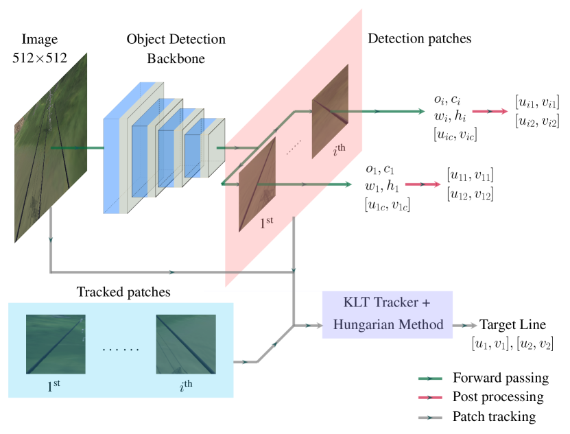
As shown in Fig. 3, our detector takes monocular RGB images as input and outputs: (i) width and height of the bounding boxes that fully contain the detected power line, where indicates the number of detection; (ii) the inclination of the line (either +1 or -1). The endpoints of positive inclined lines, i.e., , correspond to the top-left and bottom-right corners of the bounding box. The endpoints of negative inclined lines correspond to the top-right and bottom-left corners of the bounding box; (iii) the center of the line ; (iv) the confidence score of the prediction. If the confidence score is not larger than a predefined threshold (we use 0.8 in all our experiments), the detection is labeled as invalid and is not used. To perform tracking, we use a tracking-by-detection approach to track the detected power lines. In the first step, we track the center patch of the detected bounding box, of dimension 2525 pix, using a 4 layers Lukas-Kanade tracker (KLT)] [36]. In the second step, we compute the similarity score between bounding boxes in two consecutive frames as the sum of the KLT error and the area difference between the two bounding boxes normalized by the image size. In the final step, we find the best matches using the Hungarian method [35]. The final outputs are the endpoints of the tracked line in the pixel coordinate . Then we transform the endpoints, incorporating depth detection and state estimation, into the world frame to derive .
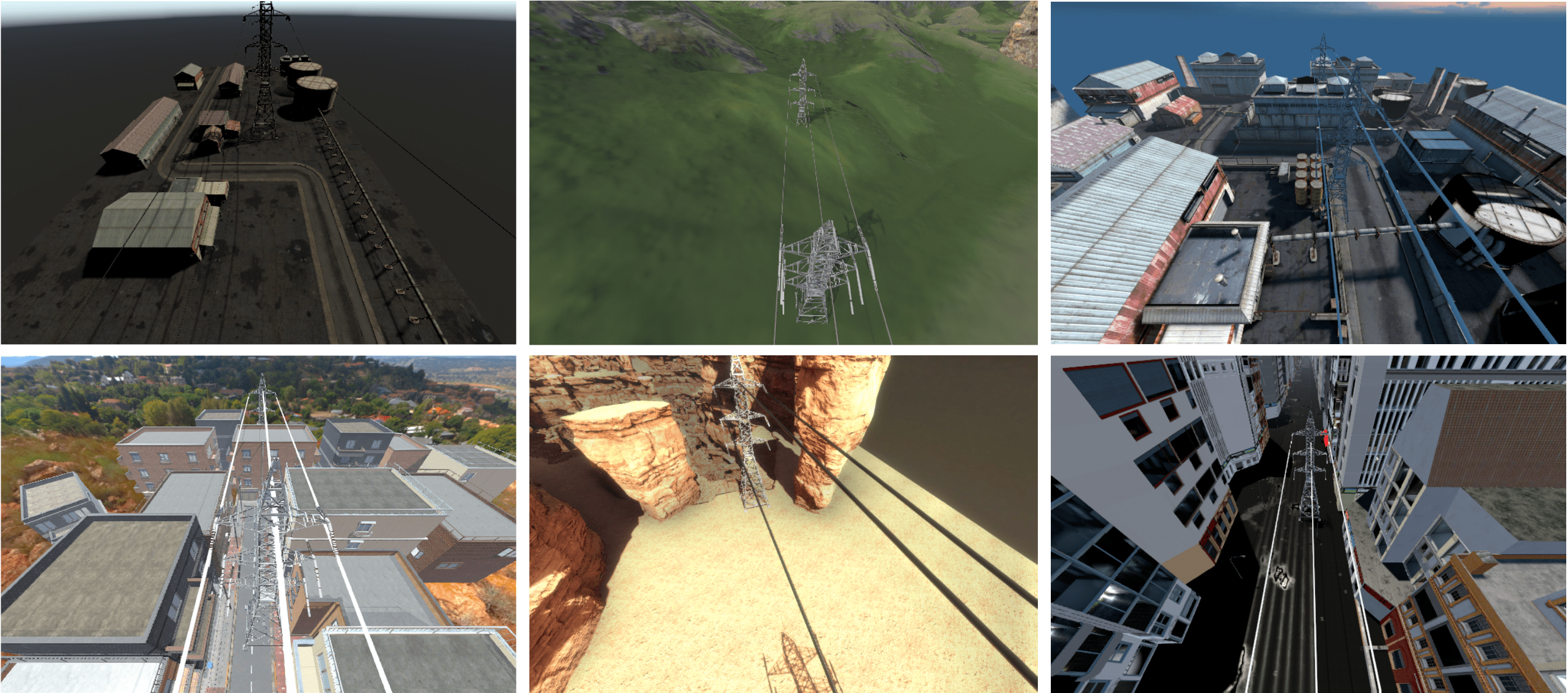
Among the datasets which contain power lines [37, 38], there is a limited amount of labeled data and scene variability. Consequently, they are not suitable for training a robust power line detector. For this reason, we created a new dataset for power line detection based on the photo-realistic simulator Flightmare [39]. We collected a dataset of 30k images of labeled power lines of different colors and thicknesses in different 6 environments (c.f. Fig. 4). The dataset is split into training (80%), validation (10%), and test (10%) sequences. We train our power line detector on the training sequence and use the validation sequence for hyperparameters tuning.
Our current approach requires that the user specifies which power line to track, e.g., the ID from the detection. The ID cannot be changed during the flight. We leave as part of future work the extension of the MPC formulation to track different lines. A current limitation of the line tracked is the missing information on the temporal history of the lines. If a power line is not tracked between two frames, the detector is unable to continue tracking the previous line. To address this issue, a possible solution would be to implement a hibernation mechanism as in [16].
III-G Obstacle Detection
We use ellipsoids with constant but unknown sizes to represent obstacles. The state of an obstacle is defined as , which contains the position of the center of the ellipsoid in the world frame and the length of its semi-principal axes. Our obstacle detection module is based on U- and V- disparity maps as proposed in [40]. The U-map is a histogram of disparity values accumulated over the columns of the image. The V-map is a histogram of disparity values accumulated over the rows of the image. These disparity maps are used to detect obstacles from depth images.
IV Experiments
In this section, we validate our system by answering the following questions:
-
•
Why use our learning-based line detector instead of classical methods?
-
•
The initial reference trajectory can be in collision with the power masts. In this case, can our system safely avoid the power masts?
-
•
Does tightly-coupled perception and action improve data quality for visual inspection?
In addition, we demonstrate our system in the real world on a mock-up power line infrastructure. The proposed perception-aware MPC runs inside the quadrotor control stack [41].
Benefits of our learning-based line detector:
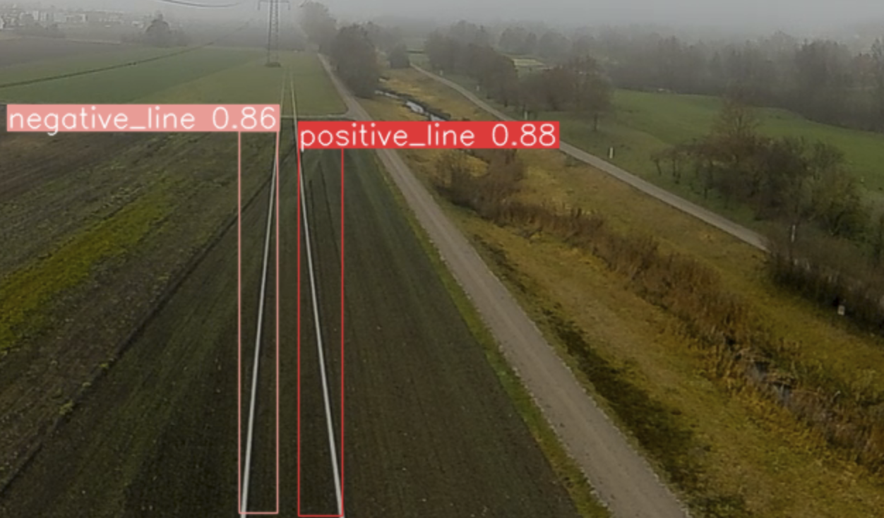
In these experiments, we compare the proposed learning-based line detector against a traditional line detector approach based on the Hough transform algorithm [42]. We design a traditional line detection baseline that uses the Canny edge detector algorithm [43] to detect edge features in the image and the Hough transform algorithm to estimate the line parameters. We also design a probabilistic version of this algorithm, Probabilistic Hough Transform (P-Hough), that runs on a sampled subset of the detected edges. The dimension of this subset depends on predefined thresholds that vary according to the number of detected edges. The parameters of the traditional approach were tuned on the training sequences of our simulated power line dataset. The results on the test sequences are listed in Table I. We use the metrics proposed in [44], which are the Precision, Recall, and the F1 score of the line matching results based on Chamfer distance and EA score [44]. Our line detector greatly outperforms the traditional approach. Generally, it is difficult to find a set of parameters for the traditional approach that generalizes to the different environments of our dataset. On the contrary, our learning-based detector is able to generalize to all the environments in the dataset. Furthermore, we demonstrate that our proposed line detector is able to generalize to real-world data without fine-tuning. Fig. 5 shows the output of the line detector on a real-world power line image recorded onboard a quadrotor. We refer the reader to the accompanying video where we include the results of our line detector on the full sequence of images recorded onboard a quadrotor flying above the real-world power lines.
| Method | Chamfer Distance | EA Score | ||||
|---|---|---|---|---|---|---|
| P | R | F | P | R | F | |
| Hough | 0.70 | 0.32 | 0.44 | 0.46 | 0.19 | 0.28 |
| P-Hough | 0.26 | 0.31 | 0.28 | 0.10 | 0.16 | 0.10 |
| Ours | 0.92 | 0.77 | 0.84 | 0.93 | 0.78 | 0.85 |
| Improvement (%) | 31 | 141 | 91 | 102 | 311 | 204 |
We also evaluate the line detection algorithms in terms of the time they need to process a single frame, which we name running time. Such a running time was computed on a laptop equipped with an Intel Xeon E3-1505M v5 (2.80GHz) CPU and Nvidia Quadro M2000M GPU, and on Nvidia Jetson TX2, which is the computer available onboard our quadrotor platform. The results are shown in Table III. Furthermore, to justify the need for the proposed line detector, we compare our approach against the state-of-the-art models [45, 46, 47, 48, 49] for pixel-wise line detection regarding the computation time.
| Method | Run Time [ms] | GFlops |
|---|---|---|
| SCNN [45] | 133.33 | 328.4 |
| LaneATT [46] | 38.46 | 70.5 |
| CondLaneNet [47] | 17.18 | 44.8 |
| Line-CNN [48] | 27.93 | - |
| PointLaneNet [49] | 14.08 | - |
| Ours | 1.80 | 0.0042 |
As shown in Table II,
the high latency of these models makes them unsuitable for real-time deployment onboard resource-constrained platforms such as quadrotors.
The high latency is mainly because these methods predict pixel-wise segmentation, which is not needed in our use case.
Robustness to unknown location of the power masts:
| Method | Run Time Laptop [ms] | Run Time TX2 [ms] |
|---|---|---|
| Hough | 7.19 | 18.52 |
| P-Hough | 4.61 | 16.13 |
| Ours | 4.69 | 20.83 |
Generally, the location of the power masts is either unavailable or GPS coordinates with errors up to several meters ( 10) are available. For this reason, it is not possible to plan a collision-free reference trajectory.
In this experimental setting, we evaluate the performance of our system in the case where the initial reference trajectory is in collision with the power masts.
We run our tests within the Flightmare simulation environment and assume that the MPC has access to the ground truth obstacle position and only vary the reference trajectory.
We designed an environment with 3 power masts (labelled A, B, C) as shown in Fig. 6.
We randomly sampled 100 starting points in a rectangular region of size 83 m in the vicinity of the power mast A (the center of A is located in the middle of the bottom edge of this rectangular region).
The endpoint is fixed 1 m away from the left side of the power mast C.
The reference trajectory given to the MPC is a straight line connecting the starting and end points with no yaw change.
Some of these reference trajectories are in collision with the power mast B.
Our system achieves a 100% success rate, i.e. no collision with the power masts.
We show in Fig. 6, 13 flown trajectories.
Benefits of tightly-coupling perception and action: In this experiment, we evaluate the benefits of tightly-coupling perception, planning, and control in terms of visibility of the power lines compared to the classical MPC formulation (c.f. Eq. 3). We use the proposed learning-based line detector and assume that the MPC has access to the ground-truth position of the power masts. We use the similarity score as the evaluation metric, which is defined as:
| (11) |
where is the normalized angular distance between the detected and the reference line, and is the normalized distance between the center points of the lines (c.f. Fig. 2). The quantity is normalized by the length of the image diagonal, where and are the image width and height, respectively. We run the experiments on the testing sequences of our dataset which are from 4 different environments: Simple, Warehouse, Forest, and Village. The results are in Table IV. Our perception-aware MPC improves the line visibility on average by 40%.
In addition, we evaluated the run time of our perception-aware MPC formulation (c.f. Eq. 10), the classical MPC formulation, an MPC including the only line tracking objective (Tracking MPC), and, an MPC including the only collision avoidance objective (Avoidance MPC). We report the update and solver time when running the algorithms on an Nvidia Jetson TX2 platform, which is the computer onboard our quadrotor. The update time is the period of time between two consecutive control commands. The solver time is the period of time taken by the solver to optimize the MPC objective. The results are shown in Table V. Our proposed MPC requires more computational time than the classical formulation mainly due to the collision objective. However, the update is fast enough to deploy the proposed MPC on a real quadrotor.
| Simple | Warehouse | Forest | Village | Mean | |
|---|---|---|---|---|---|
| Our MPC | 0.74 | 0.63 | 0.61 | 0.67 | 0.67 |
| Classical MPC | 0.53 | 0.49 | 0.44 | 0.45 | 0.48 |
| Update Time [ms] | Solver Time [ms] | |
|---|---|---|
| Classical MPC | 0.880.27 | 0.65 0.01 |
| Tracking MPC | 0.990.03 | 0.75 0.02 |
| Avoidance MPC | 7.313.15 | 7.14 3.01 |
| Our MPC | 7.903.63 | 7.673.62 |
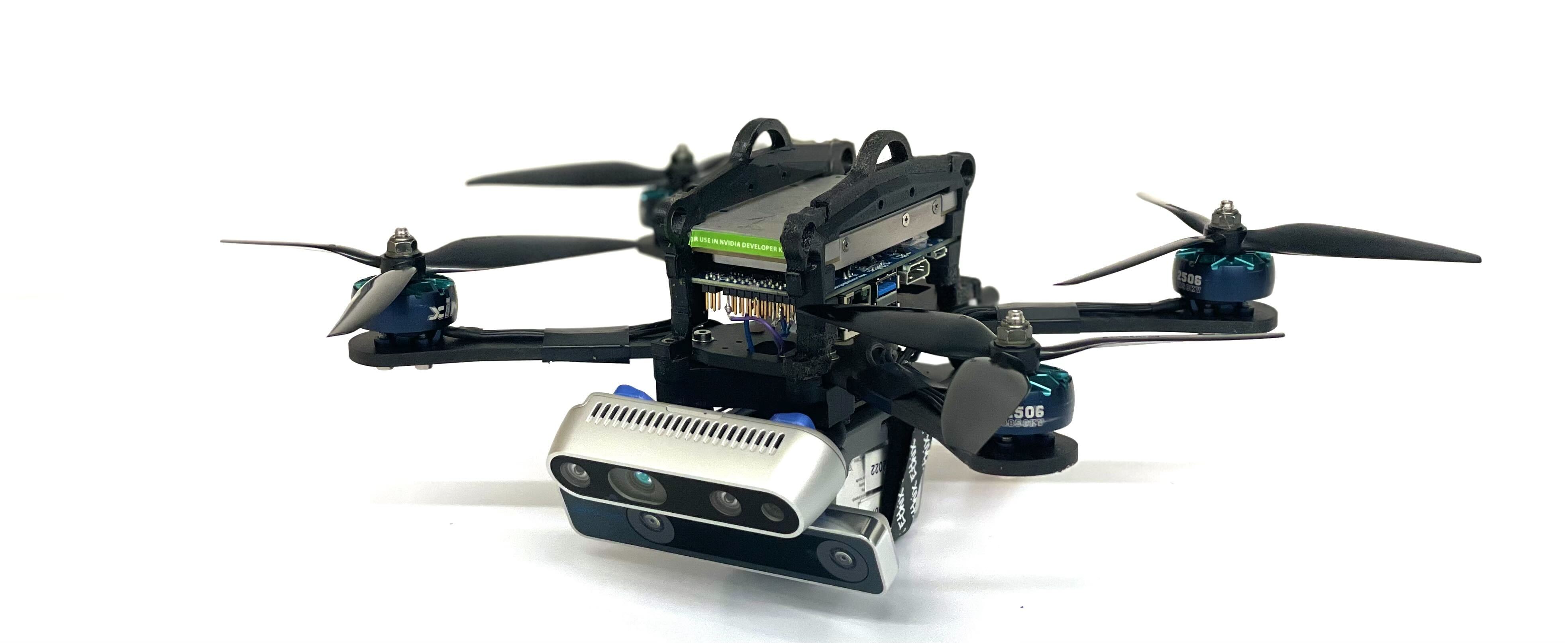
Real-world deployment: We deploy our system on a quadrotor equipped with an Intel Realsense T265 tracking camera and an Intel Realsense D435i depth camera. The onboard computer is an Nvidia Jetson TX2. Detailed information about our quadrotor platform is in [41]. We use the VIO algorithm from the tracking camera to obtain an estimate of the 6-DoF pose of the quadrotor and the depth camera to obtain RGB images for the line detection algorithm and depth measurements for the collision avoidance algorithm. All the components of our system run on the onboard computer in real-time. We set up a mock-up power line environment featuring 3 power masts. The distance between each pair of power masts is 7.5 m. A top view of the power environment including a trajectory flown by our quadrotor is in Fig LABEL:fig:catcheye. We run several experiments with different starting positions sampled in the vicinity of mast A. In all the experiments, the proposed MPC does not have access to the ground-truth location of the power lines and power masts. For this reason, a classical MPC approach without perception awareness is not a suitable solution. We demonstrate that our quadrotor is able to track the power line by adapting its heading (c.f., Fig LABEL:fig:catcheye) and to avoid the power masts. We refer the reader to the accompanying video for the visualization of these experiments.
V Conclusions
In this work, we present a system for autonomous power line inspection using perception-aware MPC. Our approach generates control commands that maximize the visibility of the power lines while safely avoiding the power masts. Our MPC formulation includes two perception objectives, one for line tracking and one for obstacle avoidance. The MPC adapts the weights of these two objectives online. To detect the power lines, we propose a novel learning-based detector. This learning-based detector is only trained on synthetic data and is able to transfer to real-world images without any fine-tuning. We show that our system is robust to unknown information on the position of the power lines and power masts. We also show that our perception-aware MPC improves power line visibility by 40%. We demonstrate a real-world application in a mock-up power line environment. Future improvements for our system might include i) improving system robustness against disturbances such as wind [50], model mismatch [51] or sensor failures [52] and ii) perching on the power line [23] in order to recharge the battery on the fly [53].
References
- [1] “Drone industry insights - drones in the energy industry: The energy drone operator benchmark,” http://droneii.com.
- [2] E. Commission, “Drone strategy 2.0: Creating a large-scale european drone market,” https://ec.europa.eu/commission/presscorner/detail/en/ip˙22˙7076, accessed: 2023-02-13.
- [3] “U.s. electric system is made up of interconnections and balancing authorities,” https://www.eia.gov/todayinenergy/detail.php?id=27152.
- [4] “Power distribution in europe facts and figures,” https://cdn.eurelectric.org/media/1835/dso˙report-web˙final-2013-030-0764-01-e-h-D66B0486.pdf.
- [5] “California’s second-largest wildfire was sparked when power lines came in contact with a tree, cal fire says,” https://edition.cnn.com/2022/01/05/us/dixie-fire-power-lines-cause-pge.
- [6] “Danmarks dronestrategi: Danish strategy for drone technology development and use,” https://ufm.dk/publikationer/2016/filer/dronestrategi-2016.pdf.
- [7] V. N. Nguyen, R. Jenssen, and D. Roverso, “Automatic autonomous vision-based power line inspection: A review of current status and the potential role of deep learning,” International Journal of Electrical Power & Energy Systems, vol. 99, pp. 107–120, 2018.
- [8] D. Falanga, P. Foehn, P. Lu, and D. Scaramuzza, “Pampc: Perception-aware model predictive control for quadrotors,” in IEEE/RSJ Int. Conf. Intell. Robot. Syst. (IROS), 2018, pp. 1–8.
- [9] J. Redmon, S. Divvala, R. Girshick, and A. Farhadi, “You only look once: Unified, real-time object detection,” in Proceedings of the IEEE conference on computer vision and pattern recognition, 2016.
- [10] K. Takaya, H. Ohta, V. Kroumov, K. Shibayama, and M. Nakamura, “Development of uav system for autonomous power line inspection,” in 2019 23rd International Conference on System Theory, Control and Computing (ICSTCC). IEEE, 2019, pp. 762–767.
- [11] X. Hui, J. Bian, Y. Yu, X. Zhao, and M. Tan, “A novel autonomous navigation approach for uav power line inspection,” in 2017 IEEE International Conference on Robotics and Biomimetics (ROBIO). IEEE, 2017, pp. 634–639.
- [12] M. Nasseri, H. Moradi, S. Nasiri, and R. Hosseini, “Power line detection and tracking using hough transform and particle filter,” in 2018 6th RSI International Conference on Robotics and Mechatronics (IcRoM). IEEE, 2018, pp. 130–134.
- [13] F. Tian, Y. Wang, and L. Zhu, “Power line recognition and tracking method for uavs inspection,” in 2015 IEEE International Conference on Information and Automation. IEEE, 2015, pp. 2136–2141.
- [14] M. Gerke and P. Seibold, “Visual inspection of power lines by uas,” in 2014 International Conference and Exposition on Electrical and Power Engineering (EPE). IEEE, 2014, pp. 1077–1082.
- [15] F. Azevedo, A. Dias, J. Almeida, A. Oliveira, A. Ferreira, T. Santos, A. Martins, and E. Silva, “Lidar-based real-time detection and modeling of power lines for unmanned aerial vehicles,” Sensors, 2019.
- [16] A. Dietsche, G. Cioffi, J. Hidalgo-Carrió, and D. Scaramuzza, “Powerline tracking with event cameras,” in 2021 IEEE/RSJ International Conference on Intelligent Robots and Systems (IROS). IEEE, 2021.
- [17] G. Gallego, T. Delbrück, G. Orchard, C. Bartolozzi, B. Taba, A. Censi, S. Leutenegger, A. J. Davison, J. Conradt, K. Daniilidis, et al., “Event-based vision: A survey,” IEEE transactions on pattern analysis and machine intelligence, vol. 44, no. 1, pp. 154–180, 2020.
- [18] S. Sun, G. Cioffi, C. De Visser, and D. Scaramuzza, “Autonomous quadrotor flight despite rotor failure with onboard vision sensors: Frames vs. events,” IEEE Robotics and Automation Letters, vol. 6, no. 2, pp. 580–587, 2021.
- [19] J. Tordesillas and J. P. How, “Panther: Perception-aware trajectory planner in dynamic environments,” IEEE Access, vol. 10, 2022.
- [20] Y. Wang, J. Ji, Q. Wang, C. Xu, and F. Gao, “Autonomous flights in dynamic environments with onboard vision,” in IEEE/RSJ Int. Conf. Intell. Robot. Syst. (IROS). IEEE, 2021, pp. 1966–1973.
- [21] H. Nguyen, M. Kamel, K. Alexis, and R. Siegwart, “Model predictive control for micro aerial vehicles: A survey,” in 2021 European Control Conference (ECC). IEEE, 2021, pp. 1556–1563.
- [22] S. Sun, A. Romero, P. Foehn, E. Kaufmann, and D. Scaramuzza, “A comparative study of nonlinear mpc and differential-flatness-based control for quadrotor agile flight,” IEEE Transactions on Robotics, 2022.
- [23] J. L. Paneque, J. R. Martínez-de Dios, A. Ollero, D. Hanover, S. Sun, A. Romero, and D. Scaramuzza, “Perception-aware perching on powerlines with multirotors,” IEEE Robotics and Automation Letters, vol. 7, no. 2, pp. 3077–3084, 2022.
- [24] A. Romero, S. Sun, P. Foehn, and D. Scaramuzza, “Model predictive contouring control for time-optimal quadrotor flight,” IEEE Transactions on Robotics, 2022.
- [25] A. T. Schwarm and M. Nikolaou, “Chance-constrained model predictive control,” AIChE Journal, vol. 45, no. 8, pp. 1743–1752, 1999.
- [26] J. Lin, H. Zhu, and J. Alonso-Mora, “Robust vision-based obstacle avoidance for micro aerial vehicles in dynamic environments,” in 2020 IEEE International Conference on Robotics and Automation (ICRA). IEEE, 2020, pp. 2682–2688.
- [27] B. Penin, P. R. Giordano, and F. Chaumette, “Vision-based reactive planning for aggressive target tracking while avoiding collisions and occlusions,” IEEE Robot. Autom. Lett., vol. 3, no. 4, 2018.
- [28] M. Diehl, H. G. Bock, H. Diedam, and P.-B. Wieber, “Fast direct multiple shooting algorithms for optimal robot control,” in Fast motions in biomechanics and robotics. Springer, 2006, pp. 65–93.
- [29] B. Houska, H. J. Ferreau, and M. Diehl, “Acado toolkit—an open-source framework for automatic control and dynamic optimization,” Optimal Control Applications and Methods, 2011.
- [30] H. J. Ferreau, C. Kirches, A. Potschka, H. G. Bock, and M. Diehl, “qpoases: A parametric active-set algorithm for quadratic programming,” Mathematical Programming Computation, vol. 6, no. 4, 2014.
- [31] R. Szeliski, Computer Vision: Algorithms and Applications, ser. Texts in Computer Science. Springer, 2010.
- [32] H. Zhu and J. Alonso-Mora, “Chance-constrained collision avoidance for mavs in dynamic environments,” IEEE Robotics and Automation Letters, vol. 4, no. 2, pp. 776–783, 2019.
- [33] T. D. Barfoot, State Estimation for Robotics - A Matrix Lie Group Approach. Cambridge University Press, 2015.
- [34] G. Jocher, A. Chaurasia, A. Stoken, J. Borovec, NanoCode012, Y. Kwon, TaoXie, K. Michael, J. Fang, imyhxy, Lorna, C. Wong, Z. Yifu, A. V, D. Montes, Z. Wang, C. Fati, J. Nadar, Laughing, UnglvKitDe, tkianai, yxNONG, P. Skalski, A. Hogan, M. Strobel, M. Jain, L. Mammana, and xylieong, “ultralytics/yolov5: v6.2 - yolov5 classification models, apple m1, reproducibility, clearml and deci.ai integrations,” 2022. [Online]. Available: https://doi.org/10.5281/zenodo.7002879
- [35] H. W. Kuhn, “The hungarian method for the assignment problem,” Naval research logistics quarterly, vol. 2, no. 1-2, pp. 83–97, 1955.
- [36] B. D. Lucas and T. Kanade, “An iterative image registration technique with an application to stereo vision,” in IJCAI’81: 7th international joint conference on Artificial intelligence, vol. 2, 1981, pp. 674–679.
- [37] H. Zhang, W. Yang, H. Yu, H. Zhang, and G.-S. Xia, “Detecting power lines in uav images with convolutional features and structured constraints,” Remote Sensing, vol. 11, no. 11, p. 1342, 2019.
- [38] R. Abdelfattah, X. Wang, and S. Wang, “Ttpla: An aerial-image dataset for detection and segmentation of transmission towers and power lines,” in Proceedings of the Asian Conference on Computer Vision, 2020.
- [39] Y. Song, S. Naji, E. Kaufmann, A. Loquercio, and D. Scaramuzza, “Flightmare: A flexible quadrotor simulator,” in Conference on Robot Learning. PMLR, 2021, pp. 1147–1157.
- [40] H. Oleynikova, D. Honegger, and M. Pollefeys, “Reactive avoidance using embedded stereo vision for mav flight,” in 2015 IEEE International Conference on Robotics and Automation (ICRA). IEEE, 2015.
- [41] P. Foehn, E. Kaufmann, A. Romero, R. Penicka, S. Sun, L. Bauersfeld, T. Laengle, G. Cioffi, Y. Song, A. Loquercio, et al., “Agilicious: Open-source and open-hardware agile quadrotor for vision-based flight,” Science Robotics, vol. 7, no. 67, p. eabl6259, 2022.
- [42] J. Illingworth and J. Kittler, “A survey of the hough transform,” Computer vision, graphics, and image processing, vol. 44, no. 1, 1988.
- [43] P. Bao, L. Zhang, and X. Wu, “Canny edge detection enhancement by scale multiplication,” IEEE transactions on pattern analysis and machine intelligence, vol. 27, no. 9, pp. 1485–1490, 2005.
- [44] K. Zhao, Q. Han, C.-B. Zhang, J. Xu, and M.-M. Cheng, “Deep hough transform for semantic line detection,” IEEE Transactions on Pattern Analysis and Machine Intelligence, 2021.
- [45] X. Pan, J. Shi, P. Luo, X. Wang, and X. Tang, “Spatial as deep: Spatial cnn for traffic scene understanding,” in Proceedings of the AAAI Conference on Artificial Intelligence, vol. 32, no. 1, 2018.
- [46] L. Tabelini, R. Berriel, T. M. Paixao, C. Badue, A. F. De Souza, and T. Oliveira-Santos, “Keep your eyes on the lane: Real-time attention-guided lane detection,” in Proceedings of the IEEE/CVF conference on computer vision and pattern recognition, 2021, pp. 294–302.
- [47] L. Liu, X. Chen, S. Zhu, and P. Tan, “Condlanenet: a top-to-down lane detection framework based on conditional convolution,” in Proceedings of the IEEE/CVF International Conference on Computer Vision, 2021, pp. 3773–3782.
- [48] X. Li, J. Li, X. Hu, and J. Yang, “Line-cnn: End-to-end traffic line detection with line proposal unit,” IEEE Transactions on Intelligent Transportation Systems, vol. 21, no. 1, pp. 248–258, 2019.
- [49] Z. Chen, Q. Liu, and C. Lian, “Pointlanenet: Efficient end-to-end cnns for accurate real-time lane detection,” in 2019 IEEE intelligent vehicles symposium (IV). IEEE, 2019, pp. 2563–2568.
- [50] G. Cioffi, L. Bauersfeld, and D. Scaramuzza, “Hdvio: Improving localization and disturbance estimation with hybrid dynamics vio,” Robotics: Science and Systems, 2023.
- [51] L. Bauersfeld, E. Kaufmann, P. Foehn, S. Sun, and D. Scaramuzza, “Neurobem: Hybrid aerodynamic quadrotor model,” Robotics: Science and Systems, 2021.
- [52] B. Sun, J. Xing, H. Blum, R. Siegwart, and C. Cadena, “See yourself in others: Attending multiple tasks for own failure detection,” in 2022 International Conference on Robotics and Automation (ICRA). IEEE, 2022, pp. 8409–8416.
- [53] R. Kitchen, N. Bierwolf, S. Harbertson, B. Platt, D. Owen, K. Griessmann, and M. A. Minor, “Design and evaluation of a perching hexacopter drone for energy harvesting from power lines,” in 2020 IEEE/RSJ International Conference on Intelligent Robots and Systems (IROS). IEEE, 2020, pp. 1192–1198.