Symmetry-based requirement for the measurement of electrical and thermal Hall conductivity under an in-plane magnetic field
Abstract
The in-plane (thermal) Hall effect is an unconventional transverse response when the applied magnetic field is in the (heat) current plane. In contrast to the normal Hall effect, the in-plane Hall effect requires the absence of certain crystal symmetries, and possibly manifests a non-trivial topology of quantum materials. An accurate estimation of the intrinsic in-plane (thermal) Hall conductivity is crucial to identify the underlying mechanisms as in the case of the Kitaev spin-liquid candidate -\ceRuCl3. Here, we give the symmetry conditions for the in-plane Hall effect and discuss the implications that may impede the experimental evaluation of the in-plane (thermal) Hall conductivity within the single-device measurement. First, the lack of symmetry in crystals can create merohedral twin domains that cancel the total Hall signal. Second, even in a twin-free crystal, the intrinsic response is potentially contaminated by the out-of-plane conduction in three-dimensional systems, which is systematically unavoidable in the in-plane Hall systems. Third, even in a quasi-two-dimensional system, the conversion of (thermal) resistivity, (), to (thermal) conductivity, () requires protocols beyond the widely-used simplified formula () due to the lack of in-plane-rotational symmetry. In principle, two independent sample devices are necessary to accurately estimate the (). As a case study, we discuss the half-integer quantization of the in-plane thermal Hall effect in the spin-disordered state of -\ceRuCl3. For an accurate measurement of the thermal Hall effect, it is necessary to avoid crystals with the merohedral twins contributing oppositely to , while the out-of-plane transport may have a negligible effect. To deal with the field-induced rotational-symmetry breaking, we propose two symmetry-based protocols, improved single-device and two-device methods. The considerations in the manuscript are generally applicable to a broad class of materials and provide a useful starting point for understanding the unconventional aspects of the in-plane Hall effect.
I Introduction.
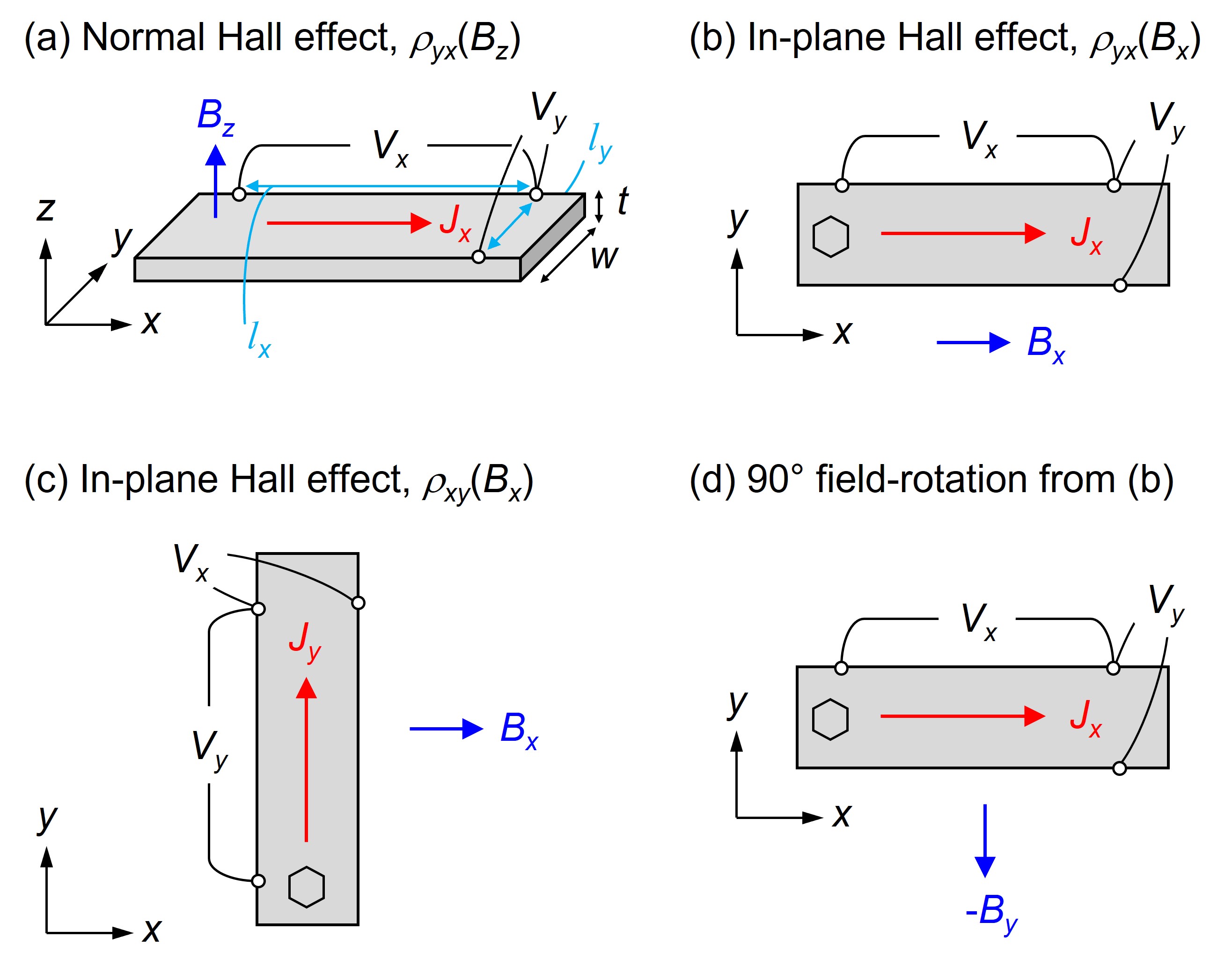
The conventional Hall effect occurs in metals and semiconductors as a transverse electric field () in an electric current along the axis () when the magnetic field () is applied along the direction (Fig. 1(a)) Hurd (1972). This is due to the Lorentz force on the conduction electrons and the changes its sign when the is reversed (). Two other types of transverse responses are known, which are induced when the magnetic field is applied in the plane. One of them is the planar Hall effect, which occurs when is rotated by an angle from the axis to the axis (Fig. 1(b)) Goldberg and Davis (1954); Koch (1955); Ky (1966). This is actually not a true field-odd Hall effect, but rather a field-even response resulting from the anisotropy of magnetoresistance Jan (1957). The other is the in-plane Hall effect, which is the main interest of this study. The typical configuration is shown in Fig. 1(c), where the applied is parallel to and the induced is reversed by the inversion of , and thus is the field-odd response 111Equivalently, the in-plane Hall effect is defined as the Hall electric field parallel to the magnetic field () when the current () is applied perpendicular to (see Fig. 5(c)).. This effect has been reported experimentally in cubic germanium as the -order effect Garcia-Moliner (1959); Grabner (1960), as well as in trigonal bismuth Okada (1956, 1957), and in monoclinic binary semimetals as the -linear effect Möllendorf and Bauhofer (1984); Bauhofer (1988).
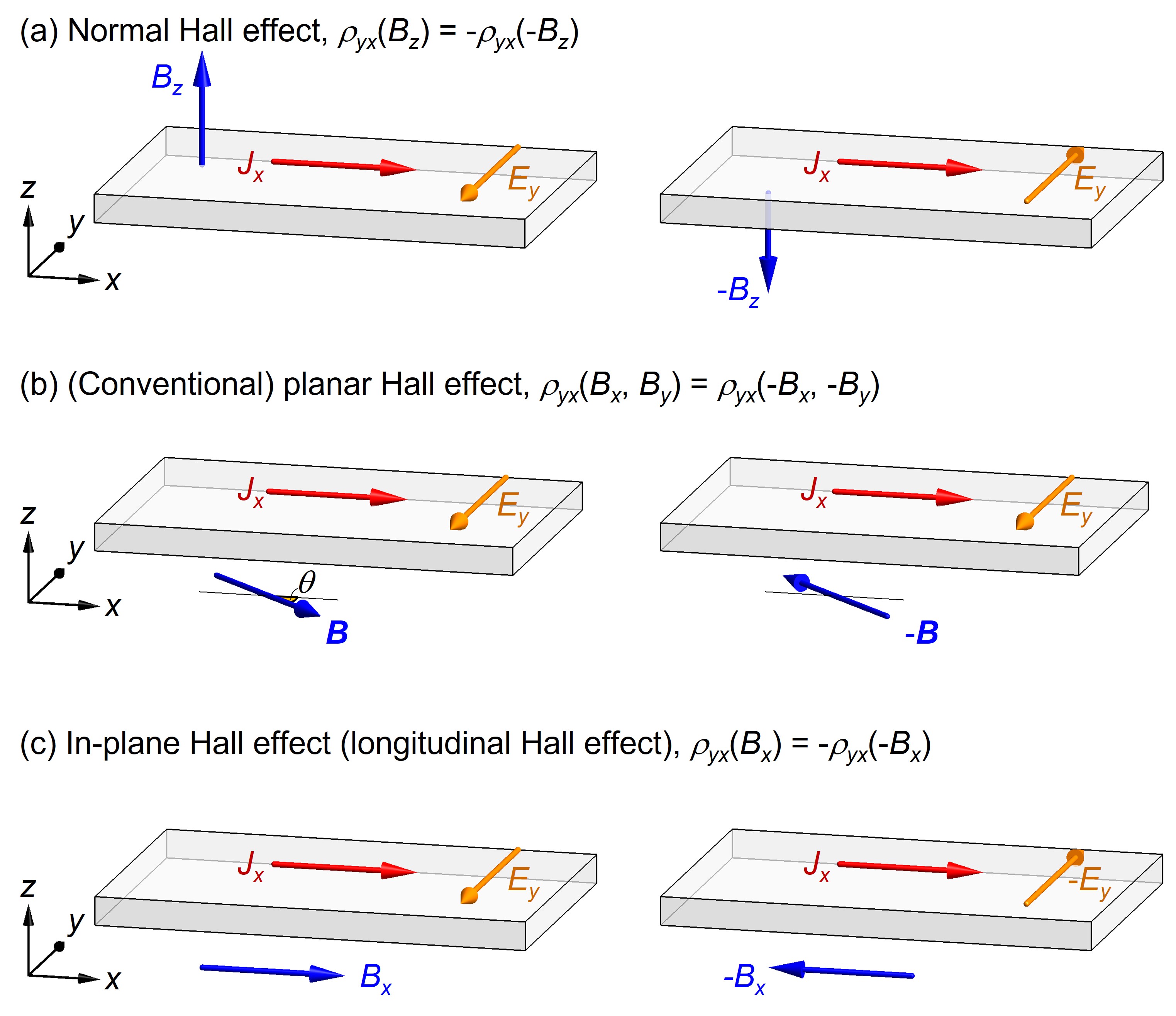
The in-plane Hall effect, or sometimes referred to as the longitudinal Hall effect, was previously recognized as a consequence of the multi-band effect Grabner (1960); Bresler and Red’ko (1972); Akgoz and Saunders (1974); Bauhofer (1985, 1988); Baltz et al. (1993); Klar and Bauhofer (1994). Independently from these early studies, this effect has recently attracted increasing interest in the context of a topological signature of quantum materials. Theories consider the quantization of the anomalous Hall effect by in-plane magnetization on magnetic topological insulators Zhang and Zhang (2011); Liu et al. (2013); Ren et al. (2016); Sheng and Nikolić (2017); Zhong et al. (2017); Zhang et al. (2019); Liu et al. (2018); Li et al. (2022), the effect of the spin-orbit interaction Mal’shukov et al. (1998); Zyuzin (2020), and the field-induced quantization in two-dimensional electron gas Zyuzin (2020); Battilomo et al. (2021); Sun et al. (2022). The role of the Berry curvature in the electron bands suggests an intrinsic (dissipationless) nature of the in-plane Hall effect in topologically non-trivial semimetals Zyuzin (2020); Cullen et al. (2021); Tan et al. (2021); Wang et al. (2022). Experimentally, the in-plane Hall conductivity is suggested to be a signature of unconventional topological transports as reported in the nonmagnetic semimetal \ceZrTe5 Liang et al. (2018), heterodimensional superlattice of \ceVS2-\ceVS Zhou et al. (2022), and magnetic half-Heusler DyPtBi Chen et al. (2022). For magnetic insulators, the in-plane thermal Hall effect has been debated to be an evidence for the chiral Majorana edge mode Kitaev (2006) in a Kitaev spin liquid candidate -\ceRuCl3 Kasahara et al. (2018a); Yokoi et al. (2021); Czajka et al. (2022); Lefrançois et al. (2022).
Importantly, the in-plane Hall effect is a consequence of the absence of certain crystal symmetries Juretschke (1955); Akgoz and Saunders (1975); Grimmer (1993). This is different from the situation for the normal Hall effect, which is always allowed by the time-reversal symmetry breaking under the out-of-plane field. As a result, several factors need to be carefully considered in order to discuss the in-plane Hall effect. In the view of the growing importance of this unconventional effect, we discuss the symmetry conditions and appropriate experimental protocols for the in-plane Hall effect, which provide a useful guide for the interpretation of the observed signal to extract the intrinsic feature of this phenomenon.
In this manuscript, we start by summarizing the symmetry requirements for the in-plane (thermal) Hall effect. We derive the absence conditions for the in-plane Hall effect by applying a pictorial approach de Figueiredo and Raab (1980), which is an extension of the previous studies to arbitrary magnetic fields in nonmagnetic and magnetic materials. It is applied to \ceZrTe5 to see if the observation in Ref. [Liang et al., 2018] is allowed by symmetry.
The following three sections address the consequences of the lack of symmetries in the in-plane Hall system. First, we consider the effect of crystal twinning, which degrades the observed in-plane Hall signal. Second, we discuss the experimental protocol for estimating the in-plane Hall conductivity by the conversion between the (thermal) resistivity tensor () and the conductivity tensor (). We show that the in-plane Hall resistivity in a (twin-free) three-dimensional system is contaminated by the out-of-plane transport, and is not directly proportional to the intrinsic in-plane Hall conductivity. Interestingly, this effect is unavoidable due to the lack of symmetry for the in-plane Hall system. Third, we consider the quasi-two-dimensional system, where the above effect is negligible. Even in this case, the effect of the in-plane magnetic field breaks the -rotational symmetry, which restricts the application of the conversion formula from () to (), and requires an approach beyond the conventional five-electrode method using a single device.
Finally, as a case study, we consider the thermal Hall effect in -\ceRuCl3 to see how the above factors affect the observations. We point out that the procedures used in previous work to quantify the thermal Hall conductivity potentially contain a systematic error. This is due to the breaking of the -rotational symmetry by the in-plane field, which has not been sufficiently verified in previous studies. We propose the improvements of the experimental protocols in order to clarify the half-integer quantization of in the spin-disordered state of -\ceRuCl3.
As a note on the terminology, we emphasize that the in-plane Hall effect differs from the conventional planar Hall effect with respect to the response to the -field reversal. In this manuscript, to follow the convention Zhou et al. (2022) and to avoid confusion, we use the term in-plane (thermal) Hall effect to refer to the field-odd response and the planar Hall effect only for the field-even response. However, a few papers use the term ”planar Hall effect” Battilomo et al. (2021); Cullen et al. (2021); Czajka et al. (2022); Takeda et al. (2022) to refer to the field-odd in-plane (anomalous/thermal) Hall effect. We do not follow this trend, as the term ”planar Hall effect” has long been used to evoke the field-even effect, although we do not say that this wording is inapprpriate 222The Hall effect is often used to describe only field-odd transverse responses Jan (1957); Casimir (1945); Zyuzin (2020), but phenomenologically it is more generally defined as being independent of the field-reversal symmetry Beer (1963); Kao and Katz (1958).
II The symmetry conditions of the in-plane Hall effect
Previous studies provide symmetry conditions of the in-plane Hall effect for nonmagnetic systems Akgoz and Saunders (1975); Kao and Katz (1958); Smith et al. (1967), for magnetic systems Grimmer (1993) upto the -linear term, and for the Berry curvature terms in nonmagnetic systems Ren et al. (2016); Wang et al. (2022). There is also a specific application to a honeycomb-lattice system Utermohlen and Trivedi (2021). To more intuitively capture the importance of crystal symmetry, we apply a pictorial approach de Figueiredo and Raab (1980) to obtain the necessary conditions for the in-plane Hall effect. This is useful for heuristically deriving the symmetry conditions of various phenomena such as nonreciprocal phenomena and multiferroicity Szaller et al. (2013); Cheong (2019); Kurumaji (2020) in both magnetic and nonmagnetic systems
We consider the equation, , which relates the electric field along the axis and the applied current along the axis under the in-plane magnetic field . We separate it into a field-even planar Hall component, and a field-odd component, , and consider only the latter, i.e., the in-plane Hall effect. We note that the conditions for are equivalent to those for because the form of the conductivity tensor is identical to that of the resistivity. All of these arguments hold regardless of the microscopic mechanism, and are even applicable to the in-plane thermal Hall effect by replacing the with the temperature gradient , and the current with the heat current.
For simplicity, we consider nonmagnetic systems in the main text, and discuss the extension to magnetic materials in SI Sec. A. We note that the in-plane Hall effect is allowed when the magnetic field is applied in an arbitrary direction with respect to the crystal axes Akgoz and Saunders (1975), which reduces the crystal symmetry to the triclinic and . We discuss rather special cases where the magnetic field is applied within a high-symmetry direction. The following four cases are the symmetry conditions for the absence of the in-plane Hall effect.
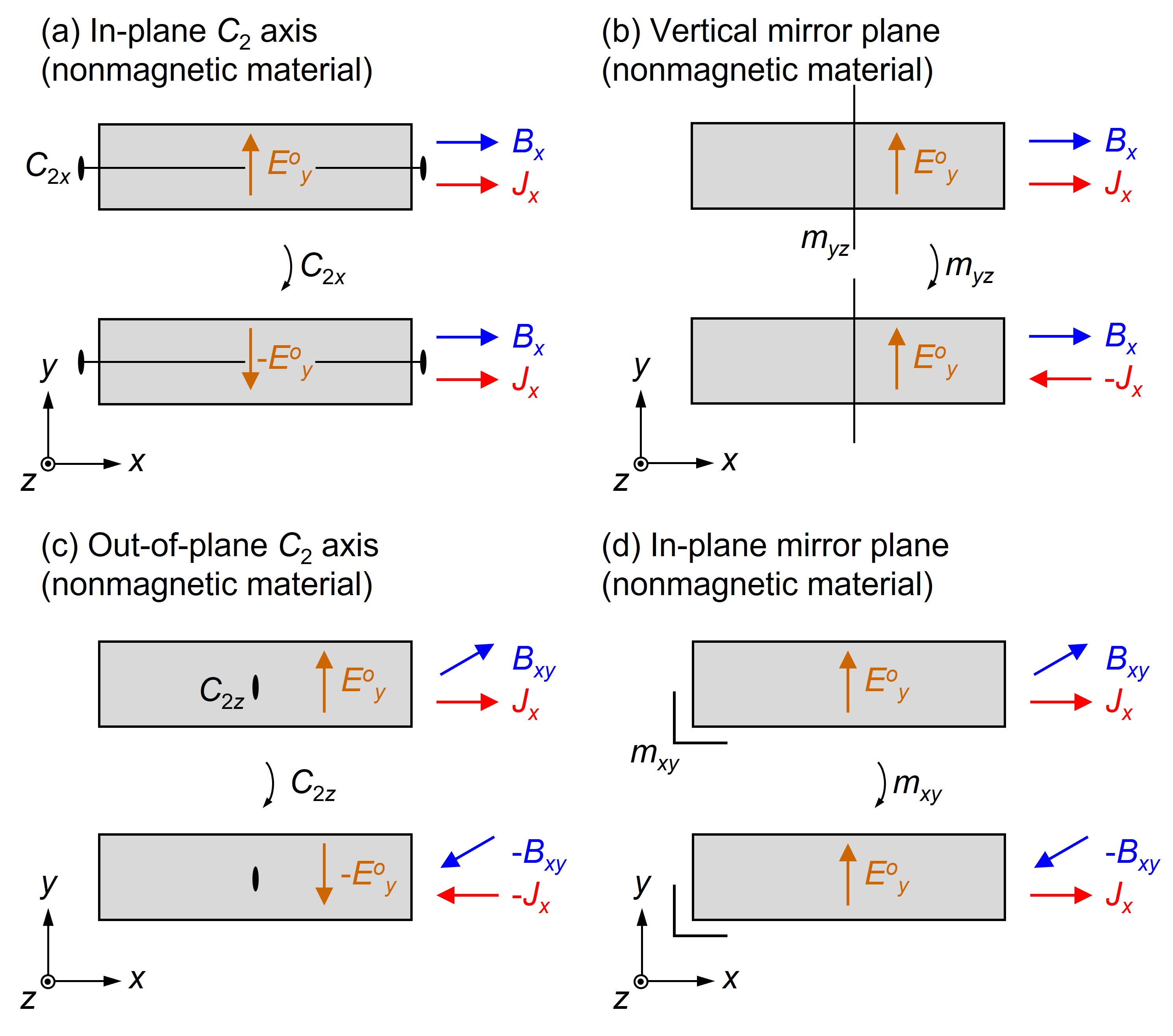
Figures 2 provide how these above conditions are validated. The top panel for each figure can be converted to the bottom one through the symmetry operation, which proves that . We consider the condition 1 as an example. Figure 2(a) considers that the sample has the axis along the axis and current flows along the axis under a magnetic field parallel to axis. We assume that the crystal has an intrinsic symmetry along the axis in zero field, and the applied field along does not break the symmetry (e.g., field-induced nematic/CDW/SDW transition involving the symmetry breaking). This last assumption is necessary to guarantee that the crystal is identical when the rotation is applied even in a finite field. As shown in the top panel of Fig. 2(a), we assume a transverse electric field along the axis () due to the in-plane Hall effect. We note that the experimental configuration is unchanged except for the direction of , when we apply the rotation to the whole experimental setup including the and the applied (see the lower panel in Fig. 2(a)). This leads to the conclusion that , i.e., . In the same way, we can prove the other conditions 2-4 in SI Sec. A.
Here, we apply the above symmetry conditions to selected examples to see if the in-plane Hall effect is allowed. Interesting contrast is obtained between the in-plane Hall effect in \ceVS2-\ceVS-superlattice Zhou et al. (2022) and in \ceZrTe5 Liang et al. (2018). As carefully discussed in Ref. [Zhou et al., 2022], monoclinic unit cell allows the in-plane Hall effect, which is consistent with the experimental results. In the case of an orthorhombic point group , however, it is indeed forbidden as long as the field is in one of the mirror planes, i.e., . Accordingly, the reported in-plane Hall effect () in \ceZrTe5 (space group: No. 63, at RT) Liang et al. (2018) is forbidden by the mirror symmetry, where the axes correspond to the crystallographic axes. The discrepancy between the symmetry condition and the experiments suggests an unrecognized symmetry lowering in the sample used, such as a monoclinic at low temperatures, or an unexpectedly large sensitivity to external shear strain or sample misalignment.
III Effect of lack of symmetry 1: twins
As shown above, the in-plane Hall effect requires that the crystals lack certain symmetries. In real materials, this feature potentially causes twinning to cancel the signal expected in a monodomain. In practice, twinned crystals are avoided for measurements, but sometimes careful inspection miss a twin by merohedry Parsons (2003), where its twin operation belongs to the holohedry point group (higher-symmetry group of the crystals). When the twin operation reverses the in-plane Hall voltage, the twin domains, crystal 1 and 2, contribute oppositely to the signal. If is the volume ratio of the crystal 1, the total in-plane Hall signal is
| (1) |
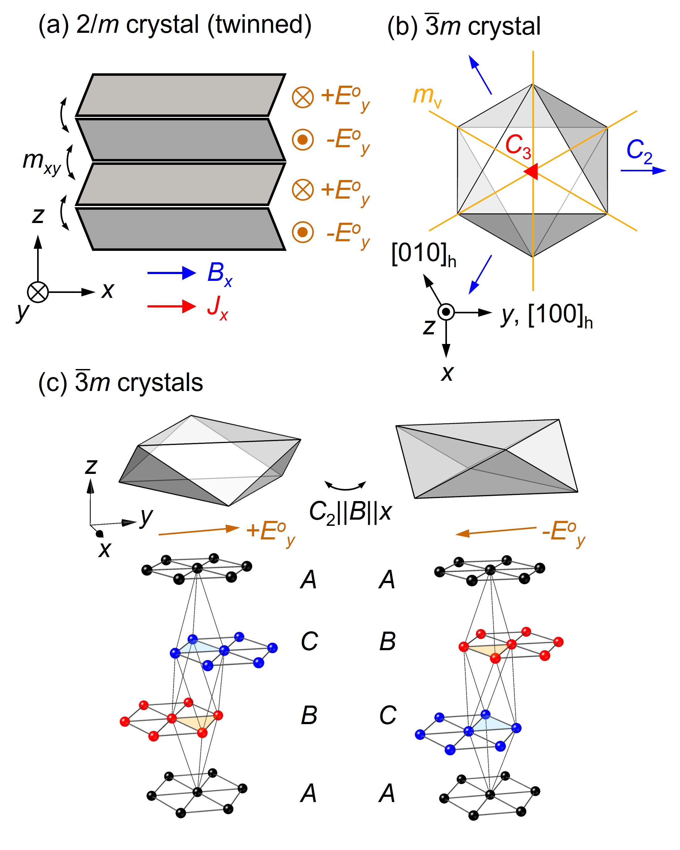
which vanishes at . Similar situation occurs due to a twin by pseudo-merohedry Parsons (2003) in a monoclinic crystal as shown in Fig. 3(a). Twinning due to a lack of mirror symmetry parallel to the plane results in the opposite contribution from each domain.
Another case is for a layered rhombohedral crystal, which potentially contains twinning by reticular merohedry (obverse-reverse twinning) Parsons (2003). We consider the crystal belonging to the point group (Fig. 3(b)). As the axis is absent along the axis, the crystal often twinned with the domain associated with the rotation along the axis (Fig. 3(c), top). Each domain contributes oppositely to the in-plane Hall signal along the axis under . This twinning occurs for example when there is the stacking fault regarding the inversion of -stacked layers to -stacked layers of triangular lattices (Fig. 3(c), bottom). To accurately evaluate the magnitude of the intrinsic in-plane Hall effect, we need to select de-twinned crystals, e.g., by checking crystallographic morphology or the extinction rules of the diffraction patterns.
IV Effect of lack of symmetry 2: Out-of-plane transport
We consider a protocol for evaluating the intrinsic in-plane Hall conductivity for a twin-free crystal. We start by considering the relationship between conductivity and resistivity. A conductivity tensor () is a matrix connecting an applied electric field () and an induced current ():
| (2) |
Instead of measuring the conductivities directly, one usually attempts to measure resistivities because it is much easier to control the direction of the in a sample than to manage the . The resistivity tensor connects the and inversely from the :
| (3) |
As the theories usually provide the predictions of the conductivity, the accurate conversion of the experimental observation to the is important to identify the underlying mechanisms of the in-plane Hall effect.
Here, we consider the following question. Suppose that we observe a non-zero , can we immediately conclude that the signal is exclusively ascribed to the finite in-plane Hall conductivity ()? It is, in fact, not the case because is contaminated with the effect of the out-of-plane transport in the three-dimensional system.
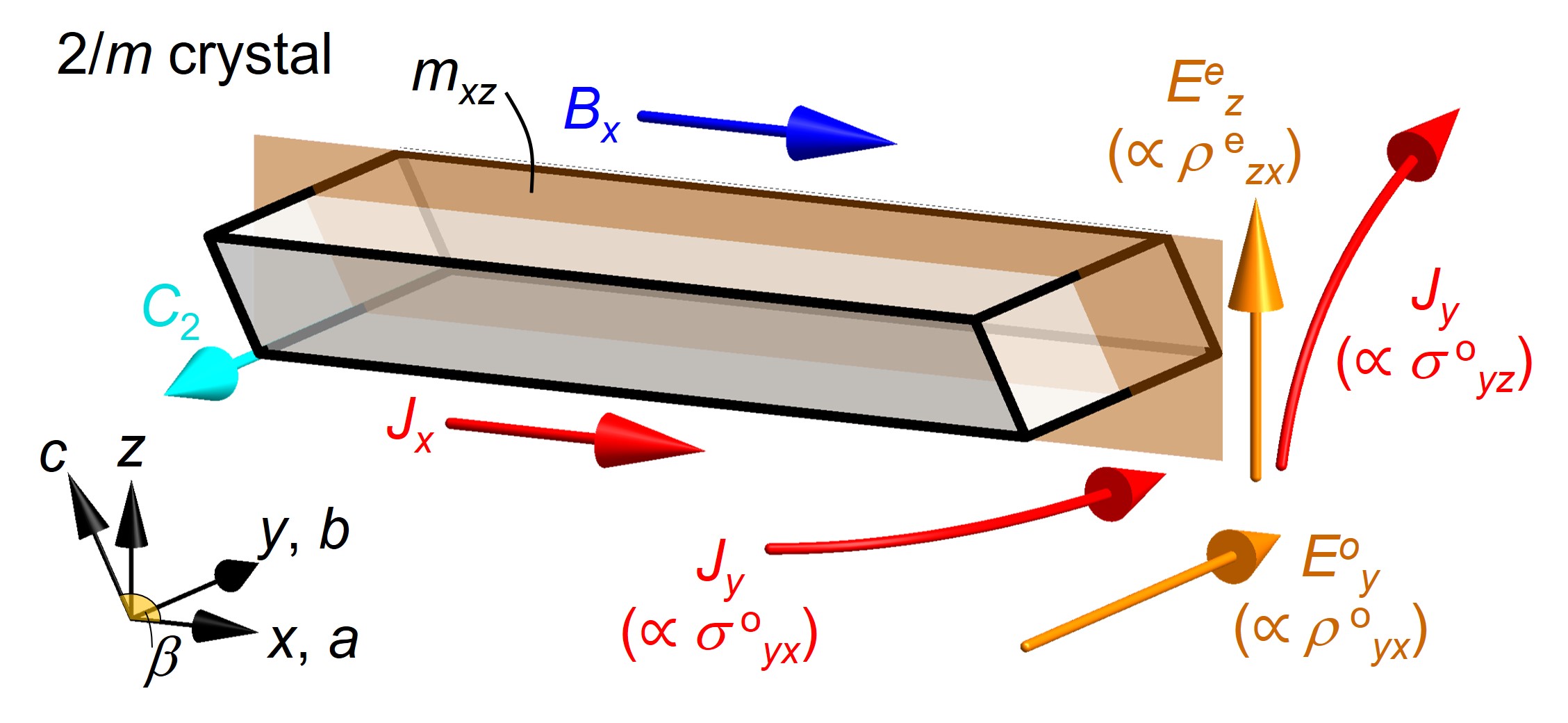
We consider a monoclinic system (Fig. 4), which provides a typical formula of our interest with respect to the in-plane Hall conductivity. The conductivity tensor is as follows,
| (4) |
Here, we set the axis parallel to the axis and the mirror plane in the plane (Fig. 4). The axis is defined as orthogonal to the plane. The superscripts, e and o, are for field-even and field-odd quantities, respectively. Since the tensor form of is identical with that of , we put
| (5) |
By taking the inverse matrix, , we obtain the formula for :
| (6) |
where is the determinant of (see SI Sec. B). We note that the is not directly proportional to the in-plane Hall conductivity , but is contaminated by the term , where corresponds to the Hall effect in the plane under . This term is finite if the field-even component is finite. We refer (and ) to the crystalline planar Hall effect (see SI Sec. C).
The contamination of the cross term between the and can be understood as shown in Fig. 4. The application of the current generates the out-of-plane electric field due to , which leads to the out-of-plane conduction . In the presence of the , the is deflected in the plane to produce the transverse , which produces an together with the intrinsic in-plane Hall current () 333In a single-carrier system, it can be proved that those two terms in Eq. (6) completely cancel with each other Bauhofer (1985) unless the Berry curvature has finite contribution. In two-carrier system, this cancellation is imperfect due to mobility difference..
It is evident that in a monoclinic crystal the can be finite even in zero field because does not guarantee the diagonalized form of the conductivity tensor. As a matter of fact, the effect due to is unavoidable for higher-symmetry systems when we consider the in-plane Hall effect of a three-dimensional system at finite field. We can prove that the symmetry condition for the finite in-plane Hall effect is equivalent to that for the (see SI Sec. C).
This contamination effect is serious if there is a significant anomalous (Berry curvature) contribution in . We consider that Hall conductivity can be divided into two terms, normal (Lorentz force origin) and anomalous (Berry curvature origin) components, i.e., and . The anomalous in-plane Hall resistivity is, then, expressed as follows.
| (7) |
Here, we omit the superscripts, e and o, for simplicity. Evidently, we cannot directly connect the observation of the with the presence of the , and need to exclude the effect from .
For quasi-two-dimensional systems, the situation is expected to become simpler. We assume that is negligible. The components is small because we can prove that , where is the out-of-plane carrier mobility. As the magnitude of cannot exceeds (since ), we can reasonably expect that the component is also restricted by the low (). These features can validate the assumption for ignoring the effect of the out-of-plane transport in the layered systems, and the approximation taking the resistivity and conductivity tenors as matrices. In the next section, we consider the case of the quasi-two-dimensional system and how the is measured.
V Effect of lack of symmetry 3: absence of -rotational symmetry.
In this section, we ignore the and components in and (Eqs. (4), (5)) for the quasi-two-dimensional system. Even in such a simplified situation, we have to consider the absence of the -rotational symmetry.
To emphasize the distinction from the conventional normal Hall effect, we first consider the measurement of the isotropic system under a magnetic field along the axis (Fig. 5(a)). A five-electrode measurement using a single-device is sufficient to estimate , where two electrodes are connected to a current source, and three are used to monitor longitudinal and transverse voltage drops. We obtain and , where and are the electrode distance for and , respectively. From the view-point of symmetry and Onsager’s relation, we can put and . We obtain the single-device formula to estimate the normal Hall conductivity
| (8) |
In contrast to the above case, the in the in-plane Hall system cannot be estimated within a single setup of the five-electrode measurement (Fig. 5(b)). The magnetoresistivity tensor when the magnetic field is applied along the axis is given by
| (9) |
Here, we assume that the symmetry of the system is high enough to have the purely field-odd off-diagonal component, i.e., no planar Hall effect (this is not true, for example, for and systems Akgoz and Saunders (1975)). Importantly, the inequality is unavoidable, in principle, because the in-plane magnetic field always breaks the rotational symmetry around the axis even in the case of the high-symmetric system in zero field (e.g., , , and ). The origin of the anisotropy can be easily understood because the longitudinal current () is less affected by the Lorentz force than the transverse current (). We also note that, in fact, the inequality often occurs in the in-plane Hall systems because it is mainly allowed in low-symmetric systems such as monoclinic crystals Möllendorf and Bauhofer (1984); Bauhofer (1988); Zhou et al. (2022).
The inverse matrix of the resistivity tensor gives the longitudinal conductivity as follows.
| (10) |
Here, we assume in the last equality that the Hall angle () is negligible. We find that the longitudinal conductivity can be estimated with sufficient accuracy within a five-electrode measurement of the setup in Fig. 5(b). The Hall conductivity (), on the other hand, is obtained in the exact form by using all three independent quantities, , , and (see SI Sec. B for the effect of three-dimensionality):
| (11) |
To estimate , we need to prepare another sample as shown in Fig. 5(c) with a long edge along the axis and perform an experiment for under . We cannot measure with the same sample for the (Fig. 5(b)) because it has to be shaped into a thin rectangular parallelpiped with a long edge along the axis to increase the signal () as well as to suppress the geometrical effect Jan (1957); Isenberg et al. (1948); Drabble and Wolfe (1957); Mumford et al. (2020).
One might consider that we can measure without changing the sample by rotating the magnetic field from to (Fig. 5(d)), which seems to be an alternative to in Eq. (9). This is in fact inapplicable because , which can be seen from the fact that a hexagon symbol on the sample in Fig. 5(d) changes its orientation when one tries to superimpose it on Fig. 5(c) by rotating the whole setup by . The inequality arises from the symmetry condition that forbids a symmetry for the non-zero in-plane Hall effect (see Fig. 2(c)), because this rule forbids symmetry at the same time. In other words, if there is a symmetry that ensures , one can prove , which is not the situation considered here.
Since the cannot be obtained within the single-device measurement using the setup in Fig. 5(b), the above formula is often replaced by the following approximate form:
| (12) |
This prescription resembles Eq. (8) for the normal Hall effect, but contains a leap of logic implicitly assuming that , which is in general invalid for the in-plane Hall system. Nevertheless, this approximate form of the Hall conductivity has often been used in many related experiments for orthorhombic/monoclinic compounds Zhou et al. (2022); Gourgout et al. (2022); Fujioka et al. (2019); Ge et al. (2020), tilted-field configuration Nayak et al. (2016); Hirschberger et al. (2021); Kasahara et al. (2018a), -plane-transport of tetragonal systems Alam et al. (2022), as well as for the in-plane thermal Hall conductivity in magnetic insulators Yokoi et al. (2021); Czajka et al. (2022); Takeda et al. (2022).
Although this does not bring a big problem in many cases for the estimation of the order of magnitude, it is crucial when the accurate value of the (thermal) Hall conductivity is connected with the theoretical interpretation of the quantum nature of the material. In principle, we need to prepare two independent devices (Figs. 5(b)-(c)) and measure , , and , to apply Eq. (11) with all three independent components. In the next section, we discuss the in-plane thermal Hall effect in -\ceRuCl3, where the quantitative evaluation of the half-integer quantization has been concluded on the basis of the approximate form of .
VI Case of the half-integer quantization of thermal Hall effect in -\ceRuCl3
Evidently, all of the above arguments are applicable to the in-plane thermal Hall effect in insulators. In particular, an accurate evaluation of the thermal Hall conductivity is important as argued in recent studies on the half-integer quantization of under an in-plane and a tilted magnetic field in a Kitaev spin-liquid candidate -\ceRuCl3 Kasahara et al. (2018a); Yokoi et al. (2021); Bruin et al. (2022a); Yamashita et al. (2020); Kasahara et al. (2022).
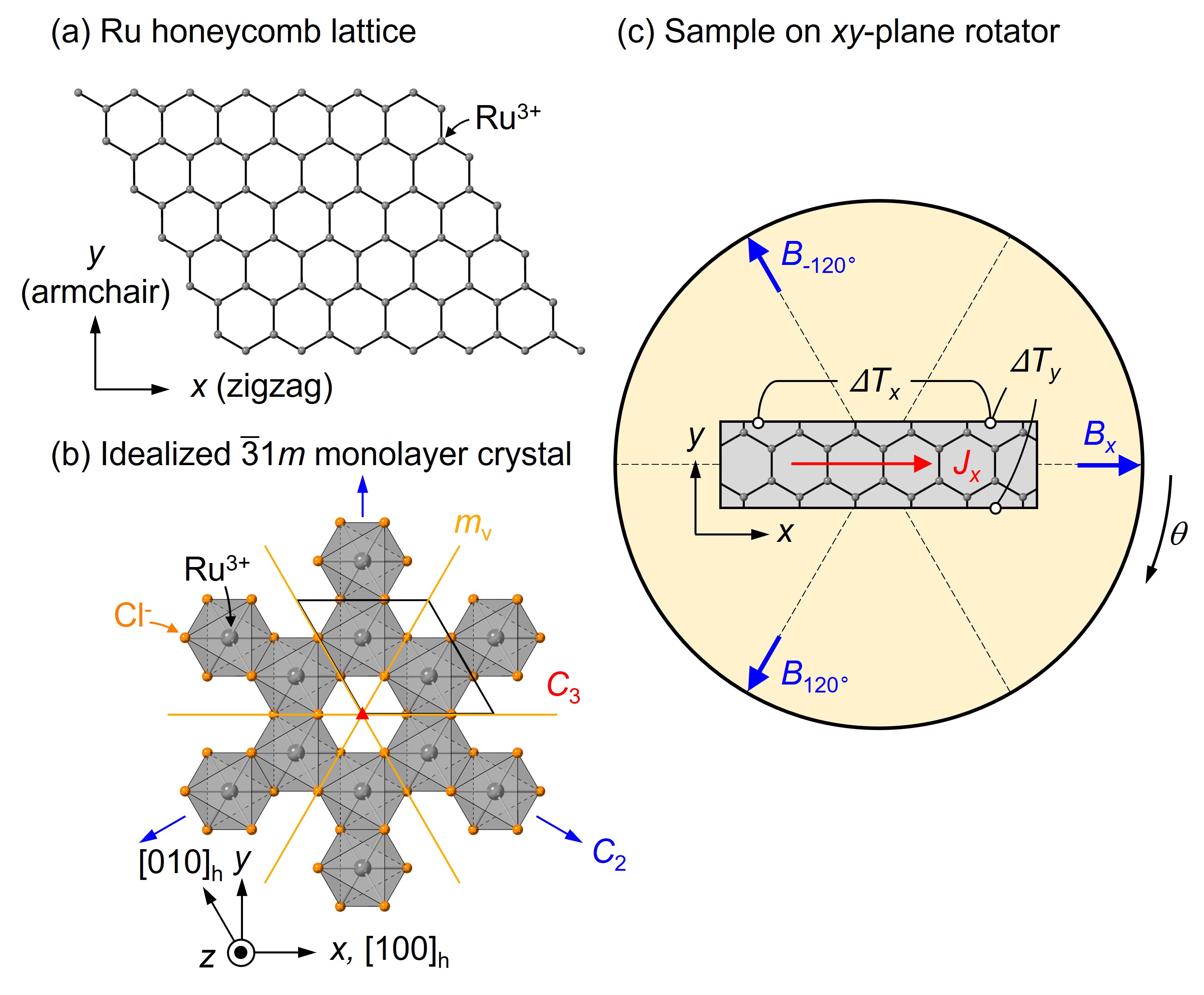
The crystal structure of -\ceRuCl3 consists of a stacked honeycomb-lattice of Ru3+ with magnetic moments (Fig. 6). There are two orthogonal axes in the lattice plane, which are called zigzag ( axis) and armchair ( axis) directions, perpendicular and parallel to a Ru-Ru bond, respectively. -\ceRuCl3 is antiferromagnetically ordered at below 7 K, and an in-plane magnetic field of 7 T is required to suppress the ordered state Kasahara et al. (2018a).
The half-integer quantization of the thermal Hall conductivity is observed in the field-induced spin-disordered state when the heat current is applied along the zigzag direction ( axis) and the magnetic field is applied along the same direction or tilted from the axis perpendicular to the honeycomb-lattice plane ( axis) towards the axis Kasahara et al. (2018a); Yokoi et al. (2021); Bruin et al. (2022a); Yamashita et al. (2020); Kasahara et al. (2022). The in-plane Hall effect in a honeycomb layer is allowed by symmetry Utermohlen and Trivedi (2021), and the absence of thermal Hall effect in the magnetic field along the armchair direction ( axis) Yokoi et al. (2021) follows the symmetry condition of honeycomb-lattice of edge-shared \ceRuCl6 octahedra Utermohlen and Trivedi (2021). The is normalized to each honeycomb-lattice with the layer separation by : , which shows a quantization to the half value of , implying the presence of the edge current of Majorana fermions Kitaev (2006); Nasu et al. (2017).
Indeed, the access to the spin-disordered state requires the in-plane component of the magnetic field, which breaks the -plane rotational symmetry regardless of the crystal structure at low temperature. The exact form of the in-plane thermal Hall conductivity is expressed by
| (13) |
and it requires all the three independent thermal resistivity components, , , and (we can reasonably ignore the effect of the out-of-plane transport; see below). In previous studies, however, the thermal Hall conductivity has been estimated by the approximate form Kasahara et al. (2018a, 2022); Yamashita et al. (2020); Czajka et al. (2021, 2022); Bruin et al. (2022b):
| (14) |
where the equivalence is implicitly assumed.
To the best of our knowledge, the component has scarcely been reported, i.e., the thermal conductivity with heat current along the armchair direction ( axis) under a field along the zigzag direction ( axis), except for Ref. [Lefrançois et al., 2023]. We summarize the references that report the thermal transport properties of -\ceRuCl3 and experimental conditions in SI Sec. D. The thermal Hall experiment with under is missing. As discussed in the above sections, we note that the cannot be replaced by , which is realized by rotating the in-plane field from to without changing the sample setup for . It is also known from the experimental results giving the different magnetic phase diagrams for and Bruin et al. (2022a); Suetsugu et al. (2022). Reference Lefrançois et al. (2023) reports both and (but no ) with different samples. They show similar -field dependence but their magnitudes are discernibly different, implying the possible anisotropy between and .
Although the significant in -\ceRuCl3 has been repeatedly observed and the plateau feature has been reproduced Kasahara et al. (2018a); Yamashita et al. (2020); Bruin et al. (2022a); Kasahara et al. (2022), there are still debates in terms of the accurate value in the spin-disordered region Czajka et al. (2022); Lefrançois et al. (2022), and microscopic origins of the Czajka et al. (2022); Chern et al. (2021); Zhang et al. (2021); Koyama and Nasu (2021); Lefrançois et al. (2022). As the theoretical predictions are provided by the , the accurate conversion process from the experimentally measured thermal resistivity to the thermal conductivity is important. The controversy is potentially due to the estimation of by the application of the approximate form Eq. (14), which may be sensitive to the sample dependence of anisotropy between and . For a more quantitative verification of the half-integer quantization, an experimental proof of the hypothesis in the spin-disordered field region has to be provided at least within the precision of better than 10% comparable to that of the geometric errors Yokoi et al. (2021). A practical difficulty would arise from the notorious sample dependence Yamashita et al. (2020); Bruin et al. (2022a), which would obscure the possible equivalence between and . We discuss two experimental protocols that take into account the sample quality variations and can be applied to -\ceRuCl3 to quantitatively verify the half-integer value of .
One of the approaches is to make use of the three-fold rotational symmetry, which is supposed to be realized in the low-temperature crystal structure of -\ceRuCl3 Tanaka et al. (2022); Park et al. (2016), although it seems to be still under discussion Bruin et al. (2022b); Kim et al. (2022); Lebert et al. (2022); Cao et al. (2016). The advantage of this method is that it can directly measure the anisotropy of the thermal resistivity under the magnetic field without changing the sample (improved single-device method). The idea is similar to the method proposed in Refs. [Shapiro et al., 2016; Walmsley and Fisher, 2017], where the elastoresistive effect is considered.
Here, we assume that the crystal structure of a monolayer -\ceRuCl3 effectively belongs to the point group, as shown in Fig. 6(b). There are three two-fold rotation axes and three vertical mirrors, which are related to each other by three-fold rotational symmetry. We note that the proposed space group at low temperature Park et al. (2016); Glamazda et al. (2017); Mu et al. (2022) is expected to make the tensor components more complicated Akgoz and Saunders (1975); Utermohlen and Trivedi (2021) due to the ferroaxial nature of the point group Gopalan and Litvin (2011); Hlinka et al. (2016). The absence of in -\ceRuCl3 Yokoi et al. (2021), which is allowed in the system, validates this setting. According to the symmetry conditions for the in-plane thermal Hall effect, the form of is obtained from Eq. (9) by replacing with .
First, we prepare a sample for the measurement with and (Fig. 6(c)). We obtain the field dependence of (), and ( with the antisymmerization by field), but not . Instead, we measure the anisotropy by rotating the magnetic field in-situ around the axis by and perform the same measurement (see left bottom of Fig. 6(c)). This configuration is similar to the planar Hall effect measurement, and the presence of the field-even off-diagonal component can be known, that is in fact proportional to .
Due to the three-fold rotational symmetry of the crystal, we can accurately predict the form of using Eq. (6) with the rotation matrix, ,
| (15) |
Accordingly, we obtain as the off-diagonal component. By measuring the field-dependence, we separate the field-symmetric and antisymmetric components in the component, respectively, as
| (16) |
and
| (17) |
We introduce the term in the first equation, which is proportional to the longitudinal component owing to the possible misalignment of the Hall electrodes.
The term can be eliminated by performing the same measurement with the field rotation by (left top of Fig. 6(c)). The field-symmetric contribution to the off-diagonal thermal Hall resistivity is given as
| (18) |
We note that the intrinsic component () is reversed from that for , while the extrinsic term is not. An antisymmetrization with respect to can be defined as . We obtain , which provides the anisotropy between and . Here, we note that the field dependence of , , and in each equation are identical to those of due to the three-fold rotational symmetry unless the demagnetization effect is significant.
The measurement can be done within a single-device by using an appropriate sample stage with rotators. The demonstration of gives a proof for , which justifies the approximate form of Eq. (14) for estimating the thermal Hall conductivity in -\ceRuCl3. Otherwise, the exact form of Eq. (13) has to be used to accurately estimate in the spin-disordered regime, suggesting the need for a correction of the reported half-integer value.
The other approach to verify in -\ceRuCl3 is to measure two different samples (two-divice method), and to utilize the thermal Hall effect itself as a sample quality check. This can be done by preparing two high-quality samples that show quantized in individual setups for the heat current parallel to the and axis (Figs. 5(b) and 5(c)), respectively. For a sample in the setup (sample X), we measure
| (19) |
With a sample in the setup (sample Y), we obtain
| (20) |
Here, we omit e and o for simplicity.
If we find that the thermal Hall plateaus are quantized to , we can confirm their comparable quality. And, we obtain an indirect proof of because
| (21) |
On the other hand, if the reproducibility of a different quantization () is established for the setup, it may be an artifact due to the approximate forms of the (Eq. (14)), and the precise thermal Hall conductivity could be estimated by a geometric mean
| (22) |
This would provide an opportunity to reconsider the true quantization value of the thermal Hall conductivity in -\ceRuCl3.
The preceding discussion is about the effect due to the possible anisotropy between and . For the quantitative evaluation of the in -\ceRuCl3, two additional effects mentioned above also have to be considered. For the proposed space group at low temperature, there are twin operations that change the orientation of the \ceRuCl6 octahedra and reverse the sign of : the operation perpendicular to the honeycomb lattice () and the mirror operation . It has been pointed out that the -stacking of the honeycomb-layers in the -stacking affects the magnetic transition temperature Kubota et al. (2015); Johnson et al. (2015); Cao et al. (2016); Bruin et al. (2022b), and such crystals can be avoided by the magnetization measurements Kasahara et al. (2018a); Yokoi et al. (2021). Since the twin domains due to the and are expected to have the same transition temperature, the twinned crystals can only be distinguished, for example, by checking the intensity profile of the electron/x-ray diffraction pattern (see SI Sec. D). As for the out-of-plane thermal transport, it has been reported Hentrich et al. (2018) to be comparable to the in-plane transport, while the out-of-plane thermal Hall effect (and also ) has not been reported. Nevertheless, this effect may be negligible as the thermal Hall angle is expected to be significantly small in magnetic insulators Ideue et al. (2017).
VII Conclusion.
Unlike the normal Hall effect, the in-plane (thermal) Hall effect is a response where the lack of crystal symmetry is essential. As a result, several factors, including crystal twinning, out-of-plane transport, and in-plane rotational symmetry, have to be taken into account in order to quantitatively evaluate the Hall conductivity under the in-plane field condition. To accurately extract the Hall conductivity from the measured resistivity components, a formalism beyond the conventionally-used formula is required because the -plane symmetry is inevitably broken.
In principle, two independent experimental setups are required to measure at least three independent components in the (thermal) resistivity tensor (two-device method). Possible sample dependence may prevent an accurate conversion to the conductivity tensors, while the values of the Hall resistivity in individual experiments can be used as a check of the equivalence of the sample quality. Another improved single-device approach using the rotation of the in-plane field is possibly available when the crystal has three-fold rotational symmetry, which is the archetype of the in-plane Hall system for the theoretical consideration of the quantized anomalous Hall effect Liu et al. (2013); Ren et al. (2016); Sheng and Nikolić (2017); Zhong et al. (2017); Zhang et al. (2019); Liang et al. (2018); Li et al. (2022), and thermal Hall effect of Kitaev-related honeycomb magnets Utermohlen and Trivedi (2021); Chern et al. (2021); Zhang et al. (2021); Koyama and Nasu (2021). The protocols presented in this manuscript would be useful to shed additional light on the experimental evidence for the quantization of in -\ceRuCl3, and more generally applicable to the evaluation of the unconventional in-plane Hall conductivity of a broader class of quantum materials.
Acknowledgements.
VIII Acknowledment
T.K. was financially supported by Ministry of Education Culture Sports Science and Technology (MEXT) Leading Initiative for Excellent Young Researchers (JPMXS0320200135), Japan Society for the Promotion of Science (JSPS) KAKENHI Grant-in-Aid for Young Scientists B (No. 21K13874). We thank L. Ye, T.-h. Arima, J. G. Checkelsky, and S. Kitou for fruitful discussion and comments on the manuscript.
IX Supplementary Materials
A A. List of point groups for the non-zero in-plane Hall effect
In the main text, we show that the in-plane Hall effect is allowed only when some symmetries are absent. As an example, we prove that the two-fold rotation axis along the magnetic field is forbidden (Condition 1, see Fig. 2(a)). The proofs for the Conditions 2 to 4 (Fig. 2(b)-(c)) are given as follows.
We can apply the corresponding logic to the system with a mirror symmetry perpendicular to the magnetic field (Condition 2, Fig. 2(b)). The orientation of is reversed by the while the sample configuration (including the induced para- or diamagnetic moment), , and remain the same. This relationship gives the equation
| (S1) |
proving that .
As for the two-fold rotational axis along the axis (Condition 3, see Fig. 2(c)), we can prove the absence of the in-plane Hall effect. This is the case when the crystal has , , , or rotational symmetry along the axis in zero field. We assume that although the magnetic field induces para- or diamagnetic moments in the plane, they do not reduce the symmetry of the system lower than , where is the time reversal operation. The rotation of the whole setup changes the upper panel to the bottom in Fig. 2(c). We obtain the following equations
| (S2) |
| (S3) |
Since , we prove that .
For the mirror symmetry in the plane (Condition 4, see Fig. 2(d)), the proof is as follows. Again, we note that the system becomes symmetric against operation under the in-plane magnetic field. The equation for the upper panel in Fig. 2(d) is , and the mirror operation to the experimental setup gives . The last equation gives to prove .
On the basis of the Conditions 1 to 4, we produce the list of the crystal point groups that allow the in-plane Hall effect. Table 1 summarizes such point groups and allowed components and field-configurations required to induce the in-plane Hall. The leading term with respect to the applied field is also shown. The absence of the orthorhombic point groups in the table indicates that they do not allow the in-plane Hall effect as long as the applied field is in the high-symmetry directions such as the plane.
| Point group | Symmetry axes | Allowed in-plane Hall effect | Leading term () |
|---|---|---|---|
| Para- or diamagnetic materials | |||
| , | arbitrary setting | ||
| , , | or | , | |
| , , | or | , | |
| , | , , | for | |
| for | |||
| , , | , or | ||
| , , | or | , | |
| , | , , | for | |
| for | |||
| , , | , or | ||
| Magnetic materials | |||
| , , | arbitrary setting | ||
| , , | or | , | |
| , , | or | , | |
| , | or | , | |
| , , | or | , | |
| , , | or | , | |
| , | or | , | |
| , , | , , | for | |
| for | |||
| , , | , or | ||
| , , | , or | ||
| , | , or | ||
| , , | or | , | |
| , , | or | , | |
| , | or | , | |
| , , | , , | for | |
| for | |||
| , , | , or | ||
| , , | , or | ||
| , | , or | ||
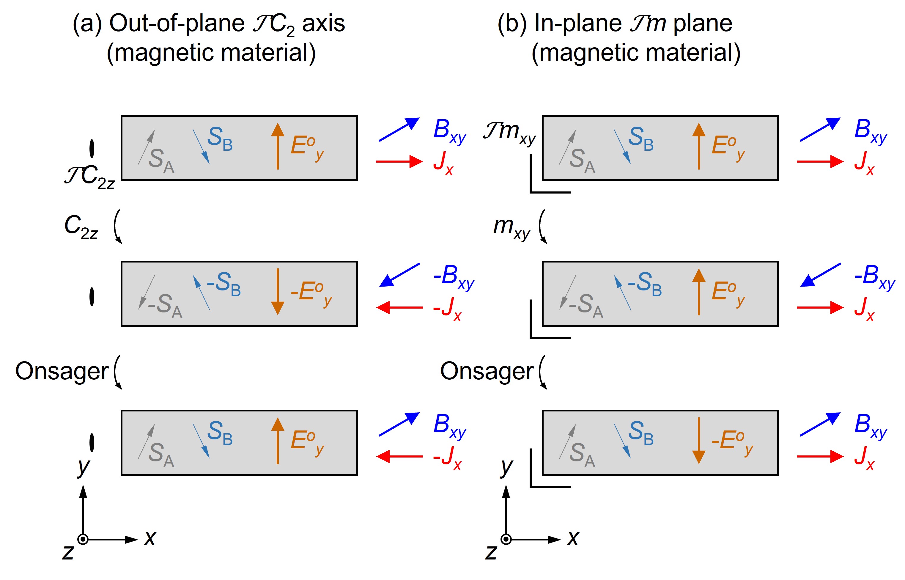
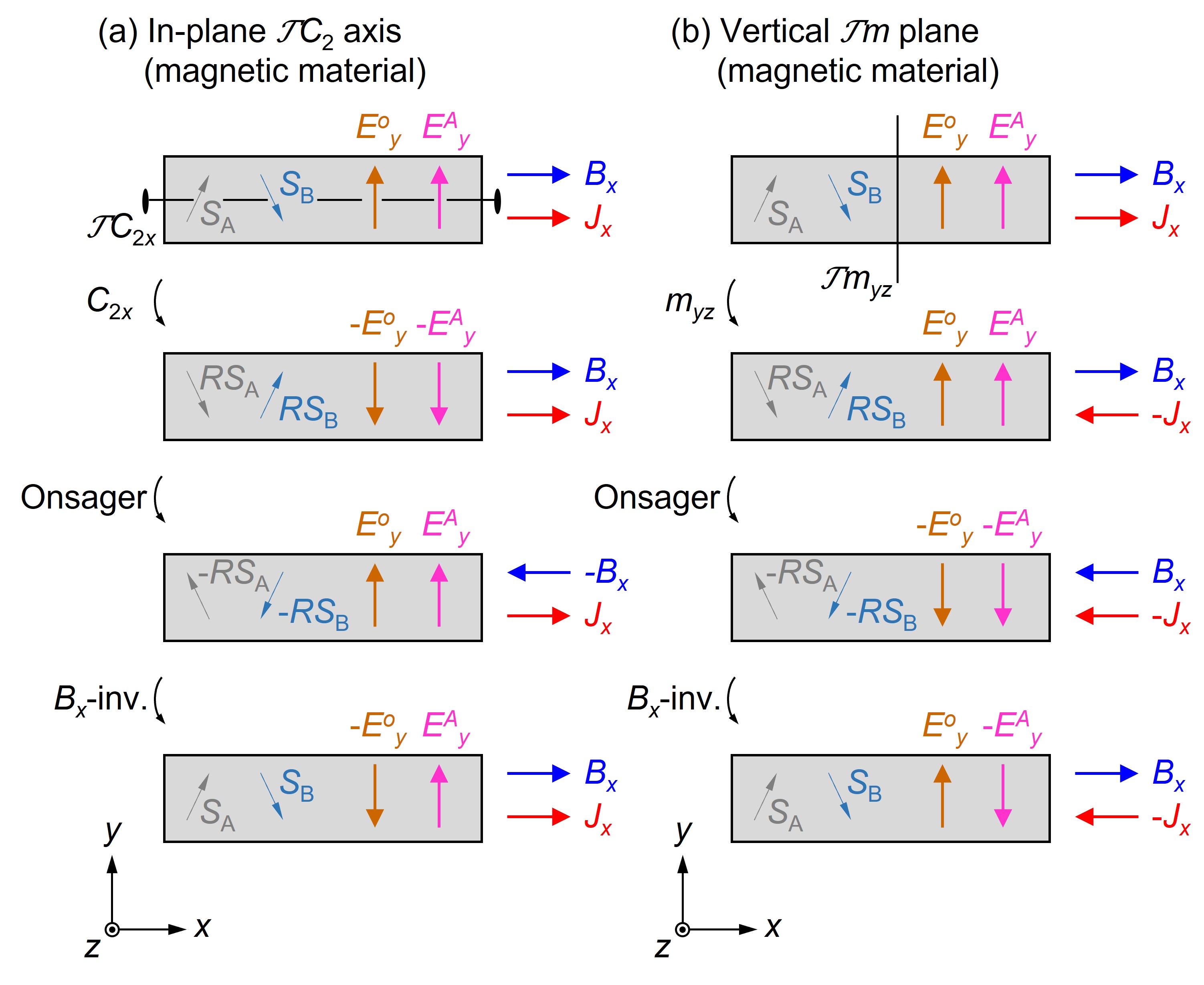
In the same table, we show the symmetry conditions for the in-plane Hall effect in the magnetic materials, where the time-reversal symmetry is broken due to internal magnetic order parameters. The low-field expansion of the Hall coefficient for all magnetic point groups has been given in Ref. Grimmer (1993), which gives the allowed Hall coefficients up to the -linear term. We present the extension to the arbitrary field region. Evidently, we can apply the same discussion to the two cases (systems with the symmetry , or , Condition 1’ and 2’, corresponding to Figs. 2(a)-(b)) considered in the main text to derive the even for magnetic materials. We also have to assume that the does not induce the further symmetry breaking that lowers the or symmetry, which would be reasonably satisfied in many materials such as ferromagnets with magnetization and two-sublattice antiferromagnets with sublattice moments . For the antiferromagnets with or or more complicated noncolinear magnets, we have to carefully check if the spin canting due to does not lower the original symmetries.
In addition to the above, there are the other six symmetries need to be considered, i.e., along the axis (Condition 3’), in the plane (Condition 4’), along the axis (Condition 5’), in the plane (Condition 6’), along the axis (Condition 7’), and in the plane (Condition 8’). We separate them into three parts, and show the pictorial approaches to prove that they give the absence of the in-plane Hall effect.
First, we consider the following two symmetry conditions: along the axis, and in the plane on the basis of Figs. S1(a)-(b).
-
3’
is zero if there is a axis along the direction under the magnetic field.
We can prove this in three steps. First, we consider the magnetic material with symmetry under a magnetic field along the axis. Figure S1(a) shows the schematic in-plane field configuration, where we symbolically introduce the internal magnetic moments, and , which represent the internal time-reversal symmetry breaking Shtrikman and Thomas (1965). In the top panel, we assume that the in-plane Hall electric field is induced by the . We apply the pure two-fold rotation to the whole setup to obtain the middle panel. We note that the internal magnetic moments are all reversed since for the -symmetric system. The internal magnetic moments can be reversed by the Onsager’s relation (see Ref. [Grimmer, 1993] for detail)
(S4) The last equation can be expressed by the bottom panel in Fig. S1(a). Comparing the top and the bottom, we find that does not change its sign even if we reverse the current direction, which gives the proof for .
-
4’
is zero if there is a in the plane under the magnetic field.
We can apply the same discussion for the above. Application of the pure operation to the whole setup reverses the magnetic field direction in the plane as well as the internal magnetic moments (top to middle in Fig. S1(b)). The Onsager’s relation gives the transformation from the middle panel to the bottom panel, which gives the opposite sign of from the top, i.e., .
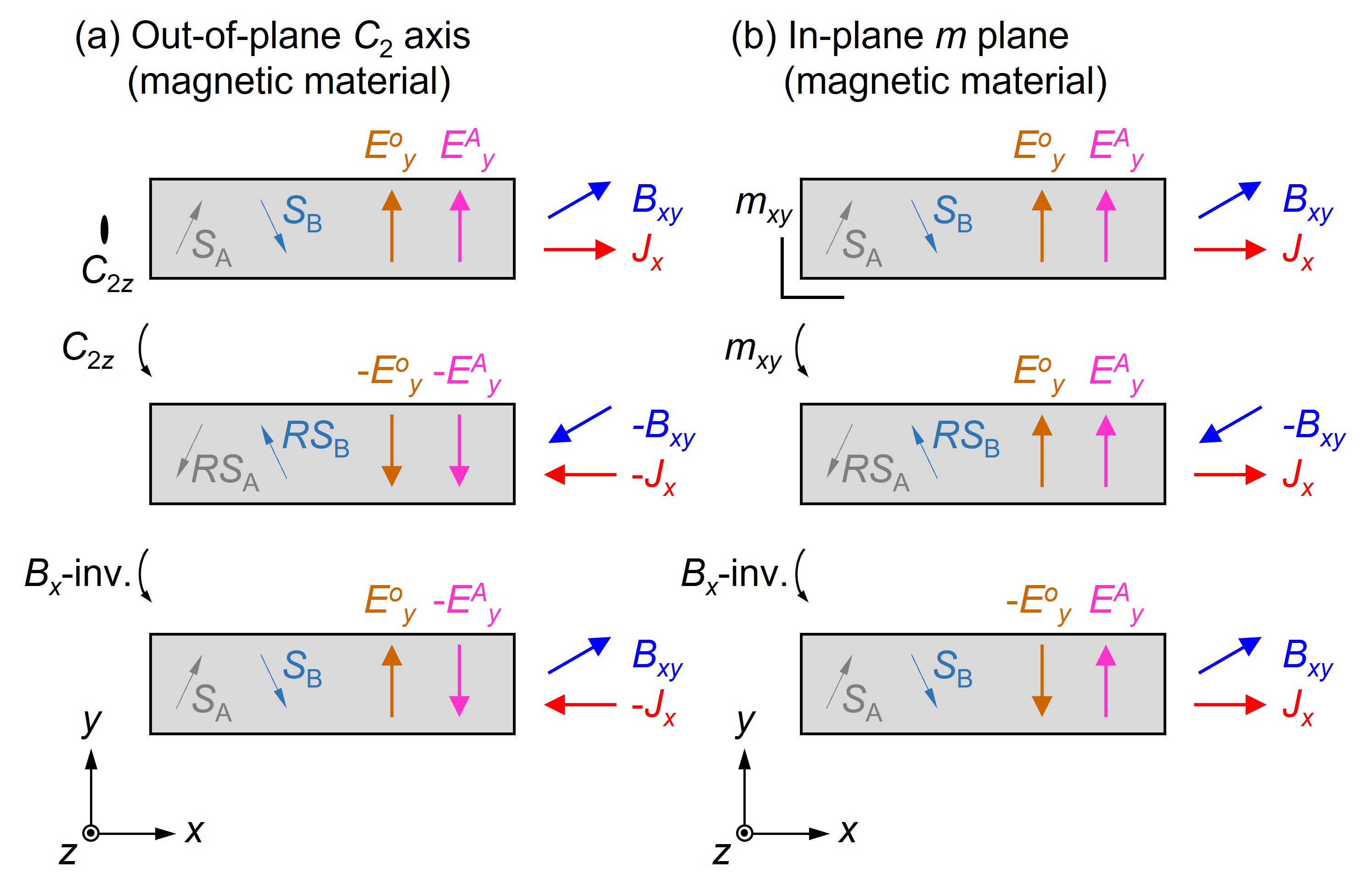
Next, we consider the other two cases: systems with symmetries or in zero field. In contrast to the nonmagnetic cases (Figs. 2(c)-(d)), the and symmetries are potentially accompanied by the anomalous Hall effect unless additional symmetries forbid the out-of-plane magnetization Grimmer (1993). Strictly, the application of the field breaks the symmetry or due to canting of magnetic moments, nevertheless, we can prove that the -field induced Hall effect to be zero. This means that we can even observe the Hall voltage under the in-plane field in such systems, but it cannot be viewed as the intrinsic in-plane Hall effect, but the field-evolution of the anomalous Hall effect . Sign of only depends on the sign of the order parameters (regarding and ) responsible for the anomalous Hall effect, i.e., its field dependence is symmetric with respect to the unless the out-of-plane magnetization is flipped.
To prove the above in the pictorial approach, we consider below.
-
5’
is zero if there is a along the axis in zero field unless the applied field flips the spontaneous magnetization.
As shown by the top panel in Fig. S2(a), we consider whether is zero in the magnetic material under . Due to the applied , the internal magnetic moments are canted to break the zero-field symmetry. Here, since the in the exact plane does not lift the degeneracy for the out-of-plane magnetization, we consider the magnetic monodomain state and assume that the possible anomalous Hall electric field is maintained to be the same sign even if the is sweeped from positive to negative. We apply the rotation to the whole system to obtain the middle panel, where the internal moments are also rotated to symbolically. The -field inversion transforms the middle to the bottom, where is reversed by definition. We can safely assume that the internal moments rotate back to keeping the sign of as the exact field does not flip the out-of-plane magnetization. Comparing the top and bottom, we obtain the proof for . In contrast to the above rather artificial setup, practically, we might have to foresee that the anomalous Hall effect would be flipped through the sweep due to potential field-misalignment towards the out-of-plane direction. This causes the apparent field-odd response of , but it should not be interpreted as the intrinsic in-plane Hall effect.
-
6’
is zero if there is a in the plane in zero field unless the applied field flips the spontaneous magnetization.
We can apply the above discussion as shown in Fig. S2(b). The mirror inversion with transforms from the top to the middle with the reversal of the internal magnetic moments to and the . The -field inversion gives the bottom panel, where goes back to the original configuration. Only the is remained reversed to give the proof for .
Lastly, we consider the remaining two cases: systems with symmetries or in zero field. These two symmetries also potentially allow the spontaneous out-of-plane magnetization and thus the anomalous Hall effect, , while the application of the field breaks the symmetries. We can prove the following two rules in the same manner described above.
-
7’
is zero if there is a along the axis in zero field unless the applied field flips the spontaneous magnetization.
As shown by the top panel in Fig. S3(a), we consider whether is zero in the magnetic material under . Due to the applied , the internal magnetic moments are canted to break symmetry for the zero field. Here, since the along the exact axis does not lift the degeneracy for the out-of-plane magnetization, we assume the possible anomalous Hall electric field is maintained to be the same sign. We apply the rotation to the whole system to obtain the second panel, where the internal moments are also rotated to symbolically. The application of the Onsager’s relation (Eq. (S4)) to the second panel leads to the third panel. Eventually, the -field inversion leads to the bottom panel, where only the is reversed by definition. We can safely assume that the internal moments rotate back to keeping the sign of as the exact field does not flip the out-of-plane magnetization. This can be know from the fact that, through the transformation from the top panel to the third, the possible out-of-plane magnetization is reversed twice by the and the Onsager’s relation to recover into the original configuration. Comparing the top and the bottom, we obtain the proof for .
-
8’
is zero if there is a in the plane in zero field unless the applied field flips the spontaneous magnetization.
We can apply the same steps as described above to Fig. S3(b). The top panel is equivalent to the bottom panel, where is unchanged even though the is reversed. This means the .
On the basis of the forbidden rules derived above, we can deduce the magnetic point groups that allow the in-plane Hall effect as summarized in Table 1 444In Ref. Tan et al. (2021), a similar table is also given, where ferromagnetic cases for each point group are considered, while the cubic groups are excluded without sufficient justification.. For example, the (magnetic) monoclinic does not show the finite aside from the anomalous Hall effect due to because of the presence of the (and as well), while it allows . As for the tetragonal point group with the rotation along the axis, we can prove because the operation of the rotation twice is equivalent with along the axis. We note that does not allow either in contrast to the case. The in-plane Hall effect is allowed for , but forbidden for because is parallel to the axis.
Similarly to the crystal twin discussed in the main text, different types of twin is expected in magnetic system, i.e., magnetic domains with respect to the time reversal. In contrast to the former, the reversal of the magnetic moments does not affect the sign of the in-plane Hall effect. We put the in-plane Hall resistivity as , where are the symbolic sublattice moments and are the -induced canting towards the field (see Ref. [Grimmer, 1993] for detail). We apply the Onsager’s relation Eq. (S4) to obtain
| (S5) | |||||
In the last equation, we assume that the -field inversion only cause the sign change of . Comparing the first and the last equation, we obtain that the sign of the sublattice magnetic moments does not affect the in-plane Hall effect.
The magnetic half-Heusler compound DyPtBi is an example showing the in-plane Hall effect Chen et al. (2022). The crystal structure belongs to in a paramagnetic state and the antiferromagnetic order breaks the time reversal symmetry. The in-plane Hall effect is allowed in the plane with the current along the axis and the magnetic field is away from the current direction as long as the mirror symmetry in the plane is maintained. The observed signal for the field parallel to the current () suggests a symmetry breaking of due to a possible field-induced canted spin texture. Further analysis of the magnetic structure would be useful to identify the symmetry breaking that enhances the in-plane Hall effect in this system.
B B. Effect of out-of-plane transport to the validity of and
In this section, we discuss how to justify the approximation of the matrices for the matrices of and . We provide the explicit form of the in Eq. (5), as the inverse matrix of in Eq. (4):
| (S6) |
where is expressed as
| (S7) |
Here, we assume that the field-odd Hall components, and are small compared to the field-even quantities, and set the quadratic form to be zero, e.g., . The is approximated as follows:
| (S8) |
We introduce two pseudo Hall angles, and The form of can be understood as being corrected from the off-diagonal-free form by . The correction is negligible when in a quasi-two-dimensional system, and Eq. (6) is reduced to , ensuring a direct proportionality between the in-plane Hall resistivity and conductivity.
Here, we discuss the form of as the inverse matrix of . The is defined as the determinant of , and is approximated by
| (S9) |
We introduce and . Similar to , the is corrected from by . The conductivity tensor components, , , and are obtained
| (S10) |
| (S11) |
and
| (S12) |
Compared to the quasi-two-dimensional forms (Eqs. (10) and (11)), both and gets a correction in the denominator due to the crystalline planar Hall effect (), which could be negligible in quasi-two-dimensional systems for , i.e., is large. As for the , the numerator in Eq. (S12) also gets a correction by the leakage from the Hall effect in the plane. The two-dimensional approximation of the (Eq. (11)) is valid only if is negligible. This is realized in quasi-two-dimensional systems with low out-of-plane carrier (electrons/phonons/magnons, etc.) mobility giving a small out-of-plane normal-Hall-angle .
C C. Symmetry conditions for non-zero
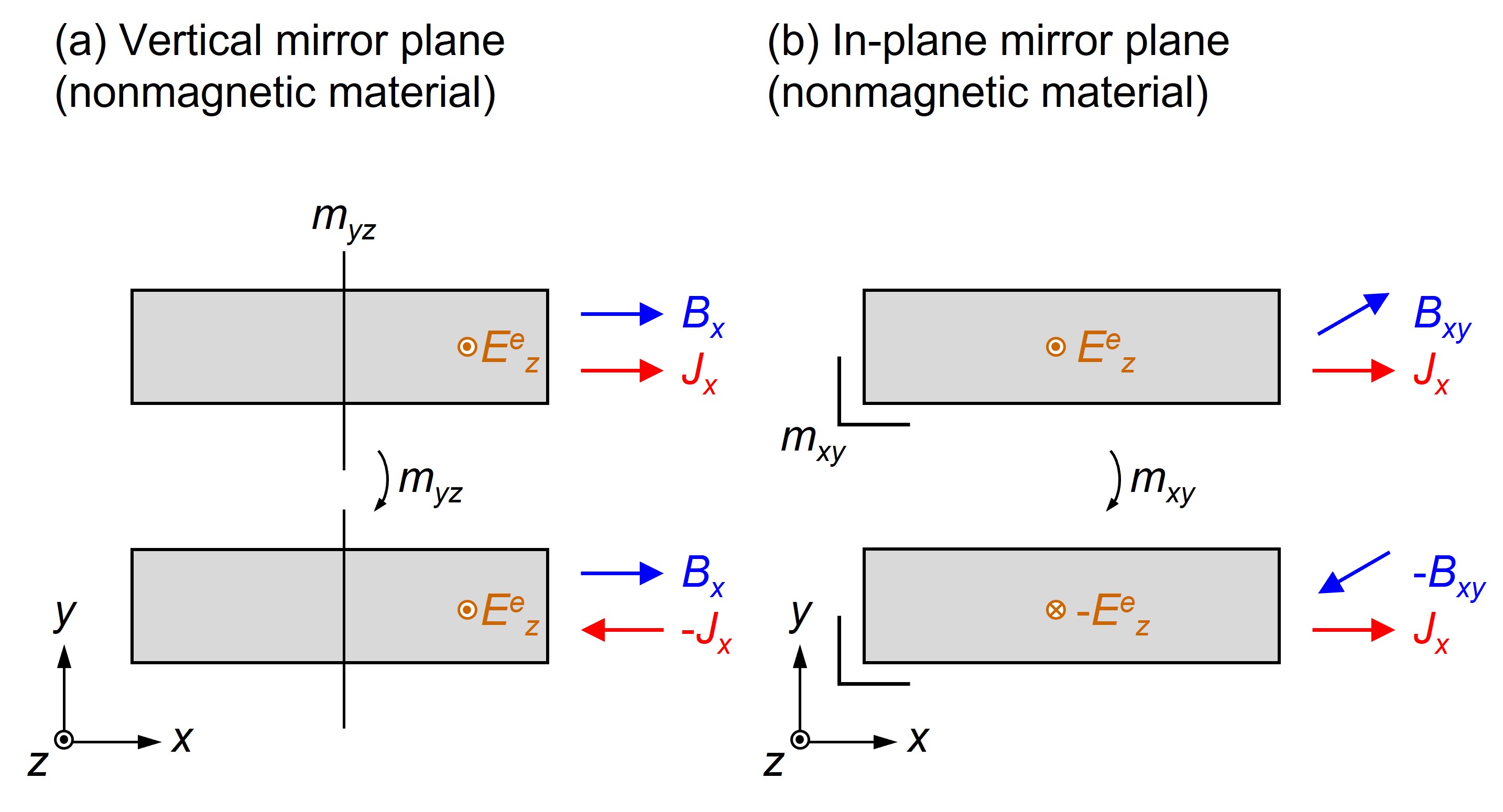
As suggested in the main text, the out-of-plane transport inevitably contaminates the in-plane Hall signal through the potentially finite . Henceforth, we refer to () as the crystalline planar Hall conductivity (resistivity). Indeed, we can prove that the conditions for the non-zero (and ) are equivalent to those for the by using the pictorial approaches regarding Figs. 2 and S1-S3.
To avoid repeating similar explanations, we show only representative cases. One example is a vertical mirror symmetry in the plane (see Fig. S4(a)). Here, we consider that a tentative out-of-plane electric field is induced by the application of , which is proved to be zero. The mirror operation transforms the system from the top to the bottom, where the and remain intact, but the is reversed. This relationship is expressed as , and thus . The other example is a horizontal mirror symmetry in the plane (see Fig. S4(b)). The mirror inversion reverses , and to give the equation . We note that , and thus obtain the proof of . We can straightforwardly prove the other conditions for the absence of .
The leading order in terms of for (and as well) depends on the crystal symmetry. Triclinic and monolcinic systems are even in zero field. Other point groups start from since it originates from the anisotropy of magnetoresistance, which is zero at .
D D. Thermal transport measurements and twin operations of -\ceRuCl3
In Table 2, we show a list of published literature reporting the thermal transport properties of -\ceRuCl3. Each raw summarizes the experimental conditions (heat current and magnetic field direction), the equations, either Eq. (13) or (14), used to estimate the thermal Hall conductivity, and growth methods for single crystals.
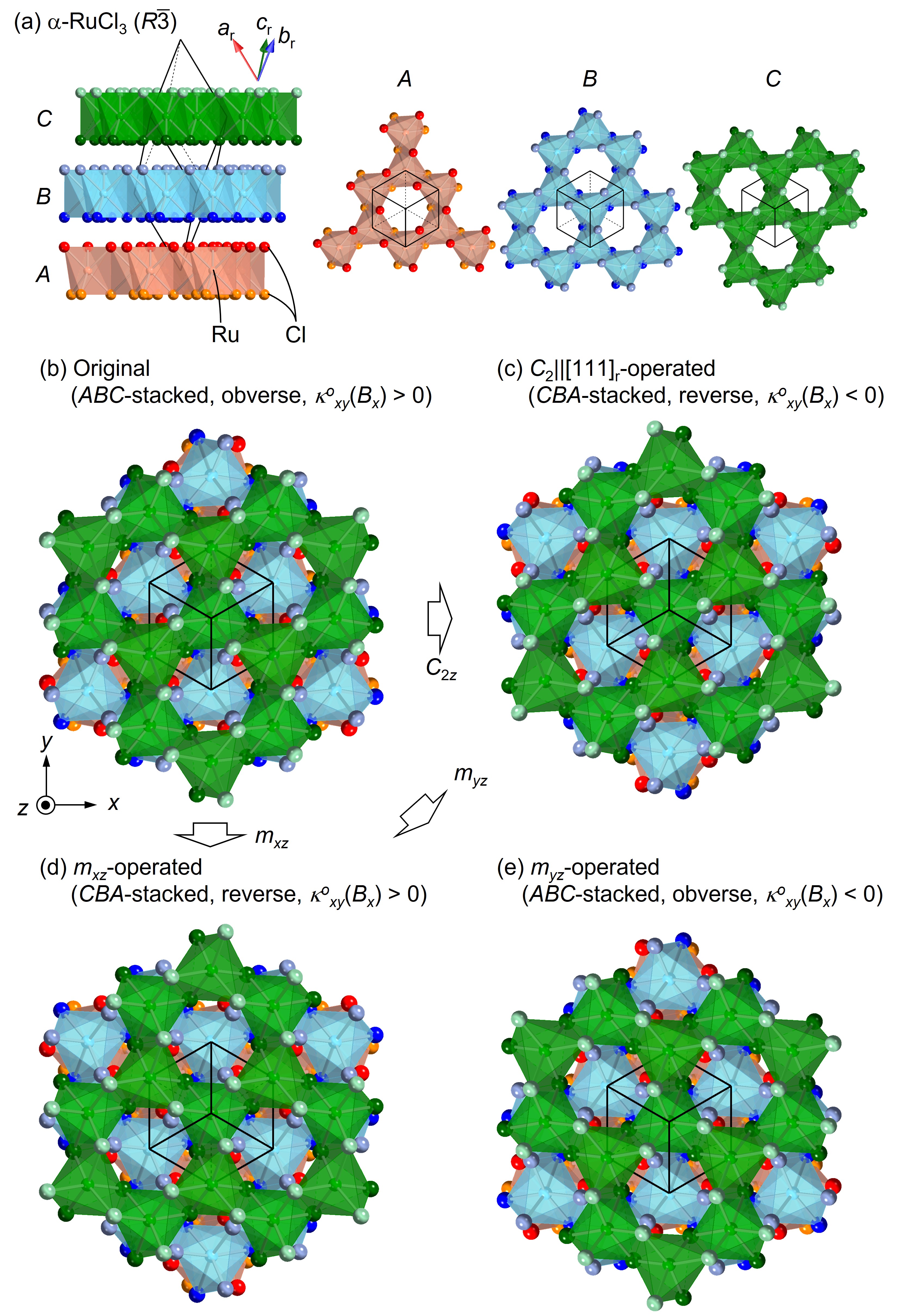
Figure S5(a) shows the proposed crystal structure of the \ceRuCl3 Park et al. (2016); Glamazda et al. (2017); Mu et al. (2022), which is described by the stacking of Cl-Ru-Cl layers along the (r denotes the rhombohedral lattice) in the order of , , and (see Fig. S5(b)). Each layer can be completely superimposed by a pure spatial translation of . As the lattice does not have the symmetries, , , and , three different types of twin domains associated with the stacking faults can be considered. Figure S5(c) shows the crystal structure after the operation. The stacking is converted to the stacking and the rhombohedral unit cell is changed to the reverse setting (see the orientation of the unit cell). As we discussed the symmetry condition for the in-plane Hall effect in Fig. 2(c), the rotation reverses the sign of the . A similar discussion can also be applied to the and operations as summarized in Figs. S5(b) and S5(c), respectively. We note that, in contrast to the case of the triangular lattice considered in Fig. 3(c), the obverse-reverse twinning (twinning by reticular merohedry) is irrelevant for the sign reversal of the . This occurs between the ferroaxial domains Gopalan and Litvin (2011); Hlinka et al. (2016) in the same obverse-reverse settings, which can be identified by electrogyration Aizu (1964); Gupta et al. (2014), and electron/x-ray diffraction Nord Jr and Lawson (1989).
| No. | Heat current | Magnetic field | Measured components | Form of | Growth method | Ref. |
|---|---|---|---|---|---|---|
| 1. | NA | NA | Bridgman | Hirobe et al.,2017 | ||
| 2. | , | NA | vacuum sublimation | Leahy et al.,2017 | ||
| , | NA | |||||
| 3. | , | exact* | Bridgman | Kasahara et al.,2018b | ||
| 4. | , | NA | CVT | Yu et al.,2018 | ||
| 5. | , | NA | CVT/vacuum sublimation | Hentrich et al.,2018 | ||
| , | NA | |||||
| 6. | toward from by and | , | approximate | Bridgman | Kasahara et al.,2018a | |
| 7. | , | exact* | CVT | Hentrich et al.,2019 | ||
| 8. | , | NA | CVT | Hentrich et al.,2020 | ||
| 9. | toward from by | , | approximate | Bridgman | Yamashita et al.,2020 | |
| 10. | , | approximate | CVT | Czajka et al.,2021 | ||
| , | approximate | |||||
| 11. | , | approximate | Bridgman | Yokoi et al.,2021 | ||
| , | approximate | |||||
| 12. | , | exact* | CVT | Lefrançois et al.,2022 | ||
| toward from | , | approximate | ||||
| 13. | , | approximate | CVT | Czajka et al.,2022 | ||
| 14. | NA | NA | Bridgman | Bruin et al.,2022a | ||
| 15. | , | approximate | Bridgman | Suetsugu et al.,2022 | ||
| , | approximate | |||||
| 16. | NA | Bridgman | Bruin et al.,2022b | |||
| NA | Bridgman | |||||
| NA | CVT | |||||
| NA | CVT | |||||
| 17. | toward from | , | approximate | Bridgman | Kasahara et al.,2022 | |
| 18. | and | NA | CVT | Lefrançois et al.,2023 | ||
| and | NA | |||||
| 19. | , | approximate | CVT | Zhang et al.,2023a | ||
| 20. | , | approximate | CVT | Zhang et al.,2023b |
References
- Hurd (1972) C. Hurd, The Hall effect in metals and alloys (Springer, 1972).
- Goldberg and Davis (1954) C. Goldberg and R. E. Davis, “New galvanomagnetic effect,” Phys. Rev. 94, 1121 (1954).
- Koch (1955) K. M. Koch, “Zum problem der galvanomagnetischen effekte in ferromagneticis,” Z. Naturforsch A 10, 496 (1955).
- Ky (1966) V. D. Ky, “Plane Hall effect in ferromagnetic metals,” Sov. Phys. JETP 23, 809 (1966).
- Jan (1957) J.-P. Jan, “Galvamomagnetic and thermomagnetic effects in metals,” in Solid State Physics, Vol. 5 (Elsevier, 1957) p. 1.
- Note (1) Equivalently, the in-plane Hall effect is defined as the Hall electric field parallel to the magnetic field () when the current () is applied perpendicular to (see Fig. 5(c)).
- Garcia-Moliner (1959) F. Garcia-Moliner, “A variational calculation of electronic transport in a magnetic field,” Proc. Roy. Soc. Lond. A 249, 73 (1959).
- Grabner (1960) L. Grabner, “Longitudinal Hall effect,” Phys. Rev. 117, 689 (1960).
- Okada (1956) T. Okada, “The measurement of the galvanomagnetic tensors of bismuth,” J. Phys. Soc. Jpn. 11, 89 (1956).
- Okada (1957) T. Okada, “The measurements of the galvanomagnetic tensors of bismuth,” J. Phys. Soc. Jpn. 12, 1327 (1957).
- Möllendorf and Bauhofer (1984) M. Möllendorf and W. Bauhofer, “First-order longitudinal Hall effect,” Phys. Rev. B 30, 1099 (1984).
- Bauhofer (1988) W. Bauhofer, “Two-band character of the first-order longitudinal Hall effect,” Phys. Rev. B 38, 5215 (1988).
- Bresler and Red’ko (1972) M. S. Bresler and N. A. Red’ko, “Galvanomagnetic phenomena in antimony at low temperatures,” Sov. Phys. JETP 34, 149 (1972).
- Akgoz and Saunders (1974) Y. C. Akgoz and G. A. Saunders, “Galvanomagnetic effects of arsenic (25.5 at%)-antimony alloy single crystals,” J. Phys. C: Solid State Phys. 7, 1655 (1974).
- Bauhofer (1985) W. Bauhofer, “Longitudinal Hall effect in \ceSrAs3,” Phys. Rev. B 32, 1183 (1985).
- Baltz et al. (1993) R. v. Baltz, W. Denk, and W. Bauhofer, “Theoretical investigation of the longitudinal Hall effect in \ceSrAs3,” Phys. Rev. B 48, 2098 (1993).
- Klar and Bauhofer (1994) P. J. Klar and W. Bauhofer, “Galvanomagnetic properties and band structure of monoclinic \ceSrAs3,” Phys. Rev. B 50, 5180 (1994).
- Zhang and Zhang (2011) Y. Zhang and C. Zhang, “Quantized anomalous Hall insulator in a nanopatterned two-dimensional electron gas,” Phys. Rev. B 84, 085123 (2011).
- Liu et al. (2013) X. Liu, H.-C. Hsu, and C.-X. Liu, “In-plane magnetization-induced quantum anomalous Hall effect,” Phys. Rev. Lett. 111, 086802 (2013).
- Ren et al. (2016) Y. Ren, J. Zeng, X. Deng, F. Yang, H. Pan, and Z. Qiao, “Quantum anomalous Hall effect in atomic crystal layers from in-plane magnetization,” Phys. Rev. B 94, 085411 (2016).
- Sheng and Nikolić (2017) X.-L. Sheng and B. K. Nikolić, “Monolayer of the transition metal trichloride \ceOsCl3: A playground for two-dimensional magnetism, room-temperature quantum anomalous Hall effect, and topological phase transitions,” Phys. Rev. B 95, 201402 (2017).
- Zhong et al. (2017) P. Zhong, Y. Ren, Y. Han, L. Zhang, and Z. Qiao, “In-plane magnetization-induced quantum anomalous Hall effect in atomic crystals of group-V elements,” Phys. Rev. B 96, 241103 (2017).
- Zhang et al. (2019) J. Zhang, Z. Liu, and J. Wang, “In-plane magnetic-field-induced quantum anomalous Hall plateau transition,” Phys. Rev. B 100, 165117 (2019).
- Liu et al. (2018) Z. Liu, G. Zhao, B. Liu, Z. F. Wang, J. Yang, and F. Liu, “Intrinsic quantum anomalous Hall effect with in-plane magnetization: searching rule and material prediction,” Phys. Rev. Lett. 121, 246401 (2018).
- Li et al. (2022) Z. Li, Y. Han, and Z. Qiao, “Chern number tunable quantum anomalous Hall effect in monolayer transitional metal oxides via manipulating magnetization orientation,” Phys. Rev. Lett. 129, 036801 (2022).
- Mal’shukov et al. (1998) A. G. Mal’shukov, K. A. Chao, and M. Willander, “Hall effect in a magnetic field parallel to interfaces of a III-V semiconductor quantum well,” Phys. Rev. B 57, R2069 (1998).
- Zyuzin (2020) V. A. Zyuzin, “In-plane Hall effect in two-dimensional helical electron systems,” Phys. Rev. B 102, 241105 (2020).
- Battilomo et al. (2021) R. Battilomo, N. Scopigno, and C. Ortix, “Anomalous planar Hall effect in two-dimensional trigonal crystals,” Phys. Rev. Research 3, L012006 (2021).
- Sun et al. (2022) S. Sun, H. Weng, and X. Dai, “Possible quantization and half-quantization in the anomalous Hall effect caused by in-plane magnetic field,” Phys. Rev. B 106, L241105 (2022).
- Cullen et al. (2021) J. H. Cullen, P. Bhalla, E. Marcellina, A. R. Hamilton, and D. Culcer, “Generating a topological anomalous Hall effect in a nonmagnetic conductor: An in-plane magnetic field as a direct probe of the Berry curvature,” Phys. Rev. Lett. 126, 256601 (2021).
- Tan et al. (2021) H. Tan, Y. Liu, and B. Yan, “Unconventional anomalous Hall effect from magnetization parallel to the electric field,” Phys. Rev. B 103, 214438 (2021).
- Wang et al. (2022) H. Wang, Y.-X. Huang, H. Liu, X. Feng, J. Zhu, W. Wu, C. Xiao, and S. A Yang, “Theory of intrinsic in-plane Hall effect,” arXiv preprint arXiv:2211.05978 (2022).
- Liang et al. (2018) T. Liang, J. Lin, Q. Gibson, S. Kushwaha, M. Liu, W. Wang, H. Xiong, J. A. Sobota, M. Hashimoto, P. S. Kirchmann, et al., “Anomalous Hall effect in \ceZrTe5,” Nat. Phys. 14, 451 (2018).
- Zhou et al. (2022) J. Zhou, W. Zhang, Y.-C. Lin, J. Cao, Y. Zhou, W. Jiang, H. Du, B. Tang, J. Shi, B. Jiang, et al., “Heterodimensional superlattice with in-plane anomalous Hall effect,” Nature 609, 46 (2022).
- Chen et al. (2022) J. Chen, H. Li, B. Ding, P. Chen, T. Guo, X. Xu, D. Zheng, H. Zhang, X. Xi, and W. Wang, “Unconventional anomalous Hall effect in the canted antiferromagnetic half-Heusler compound \ceDyPtBi,” Adv. Funct. Mater. 32, 2107526 (2022).
- Kitaev (2006) A. Kitaev, “Anyons in an exactly solved model and beyond,” Ann. Phys. 321, 2 (2006).
- Kasahara et al. (2018a) Y. Kasahara, T. Ohnishi, Y. Mizukami, O. Tanaka, S. Ma, K. Sugii, N. Kurita, H. Tanaka, J. Nasu, Y. Motome, et al., “Majorana quantization and half-integer thermal quantum Hall effect in a Kitaev spin liquid,” Nature 559, 227 (2018a).
- Yokoi et al. (2021) T. Yokoi, S. Ma, Y. Kasahara, S. Kasahara, T. Shibauchi, N. Kurita, H. Tanaka, J. Nasu, Y. Motome, C. Hickey, et al., “Half-integer quantized anomalous thermal Hall effect in the Kitaev material candidate -\ceRuCl3,” Science 373, 568 (2021).
- Czajka et al. (2022) P. Czajka, T. Gao, M. Hirschberger, P. Lampen-Kelley, A. Banerjee, N. Quirk, D. Mandrus, S. Nagler, and N. P. Ong, “Planar thermal Hall effect of topological bosons in the Kitaev magnet -\ceRuCl3,” Nat. Mater. 22, 36 (2022).
- Lefrançois et al. (2022) É. Lefrançois, G. Grissonnanche, J. Baglo, P. Lampen-Kelley, J.-Q. Yan, C. Balz, D. Mandrus, S. E. Nagler, S. Kim, Y.-J. Kim, et al., “Evidence of a phonon Hall effect in the Kitaev spin liquid candidate -\ceRuCl3,” Phys. Rev. X 12, 021025 (2022).
- Juretschke (1955) H. J. Juretschke, “Symmetry of galvanomagnetic effects in antimony,” Acta Cryst. 8, 716 (1955).
- Akgoz and Saunders (1975) Y. C. Akgoz and G. A. Saunders, “Space-time symmetry restrictions on the form of transport tensors. I. Galvanomagnetic effects,” J. Phys. C: Solid State Physics 8, 1387 (1975).
- Grimmer (1993) H. Grimmer, “General relations for transport properties in magnetically ordered crystals,” Acta Cryst. A 49, 763 (1993).
- de Figueiredo and Raab (1980) I. M. B. de Figueiredo and R. E. Raab, “A pictorial approach to macroscopic space-time symmetry, with particular reference to light scattering,” Proc. R. Soc. Lond. A 369, 501 (1980).
- Takeda et al. (2022) H. Takeda, J. Mai, M. Akazawa, K. Tamura, J. Yan, K. Moovendaran, K. Raju, R. Sankar, K.-Y. Choi, and M. Yamashita, “Planar thermal Hall effects in the Kitaev spin liquid candidate \ceNa2Co2TeO6,” Phys. Rev. Research 4, L042035 (2022).
- Note (2) The Hall effect is often used to describe only field-odd transverse responses Jan (1957); Casimir (1945); Zyuzin (2020), but phenomenologically it is more generally defined as being independent of the field-reversal symmetry Beer (1963); Kao and Katz (1958).
- Kao and Katz (1958) L. P. Kao and E. Katz, “Phenomenological theory of anisotropic isothermal galvanomagnetic effects,” J. Phys. Chem. Solids 6, 223 (1958).
- Smith et al. (1967) A. C. Smith, J. F. Janak, and R. B. Adler, Electronic conduction in solids (McGraw-Hill, New York, 1967).
- Utermohlen and Trivedi (2021) F. G. Utermohlen and N. Trivedi, “Symmetry analysis of tensors in the honeycomb lattice of edge-sharing octahedra,” Physical Review B 103, 155124 (2021).
- Szaller et al. (2013) D. Szaller, S. Bordács, and I. Kézsmárki, “Symmetry conditions for nonreciprocal light propagation in magnetic crystals,” Phys. Rev. B 87, 014421 (2013).
- Cheong (2019) S.-W. Cheong, “SOS: symmetry-operational similarity,” npj Quantum Mater. 4, 1 (2019).
- Kurumaji (2020) T. Kurumaji, “Spiral spin structures and skyrmions in multiferroics,” Phys. Sci. Rev. 5 (2020).
- Parsons (2003) S. Parsons, “Introduction to twinning,” Acta Cryst. D 59, 1995 (2003).
- Note (3) In a single-carrier system, it can be proved that those two terms in Eq. (6) completely cancel with each other Bauhofer (1985) unless the Berry curvature has finite contribution. In two-carrier system, this cancellation is imperfect due to mobility difference.
- Isenberg et al. (1948) I. Isenberg, B. R. Russell, and R. F. Greene, “Improved method for measuring Hall coefficients,” Rev. Sci. Instr. 19, 685 (1948).
- Drabble and Wolfe (1957) J. R. Drabble and R. Wolfe, “Geometrical effects in transverse magnetoresistance measurements,” Intl. J. Electronics 3, 259 (1957).
- Mumford et al. (2020) S. Mumford, T. Paul, E. Kountz, and A. Kapitulnik, “Sample shape and boundary dependence of measured transverse thermal properties,” J. Appl. Phys. 128, 175105 (2020).
- Gourgout et al. (2022) A. Gourgout, M. Leroux, J.-L. Smirr, M. Massoudzadegan, R. P. S. M. Lobo, D. Vignolles, C. Proust, H. Berger, Q. Li, G. Gu, et al., “Magnetic freeze-out and anomalous Hall effect in \ceZrTe5,” npj Quantum Mater. 7, 1 (2022).
- Fujioka et al. (2019) J. Fujioka, R. Yamada, M. Kawamura, S. Sakai, M. Hirayama, R. Arita, T. Okawa, D. Hashizume, M. Hoshino, and Y. Tokura, “Strong-correlation induced high-mobility electrons in Dirac semimetal of perovskite oxide,” Nat. Commun. 10, 1 (2019).
- Ge et al. (2020) J. Ge, D. Ma, Y. Liu, H. Wang, Y. Li, J. Luo, T. Luo, Y. Xing, J. Yan, D. Mandrus, et al., “Unconventional Hall effect induced by Berry curvature,” Natl. Sci. Rev. 7, 1879 (2020).
- Nayak et al. (2016) A. K. Nayak, J. E. Fischer, Y. Sun, B. Yan, J. Karel, A. C. Komarek, C. Shekhar, N. Kumar, W. Schnelle, J. Kübler, et al., “Large anomalous Hall effect driven by a nonvanishing Berry curvature in the noncolinear antiferromagnet \ceMn3Ge,” Sci. Adv. 2, e1501870 (2016).
- Hirschberger et al. (2021) M. Hirschberger, S. Hayami, and Y. Tokura, “Nanometric skyrmion lattice from anisotropic exchange interactions in a centrosymmetric host,” New J. Phys. 23, 023039 (2021).
- Alam et al. (2022) M. S. Alam, A. Fakhredine, M. Ahmed, P. K. Tanwar, H.-Y. Yang, F. Tafti, G. Cuono, R. Islam, B. Singh, A. Lynnyk, et al., “Sign change of anomalous Hall effect and anomalous Nernst effect in the Weyl semimetal \ceCeAlSi,” Phys. Rev. B 107, 085102 (2022).
- Bruin et al. (2022a) J. A. N. Bruin, R. R. Claus, Y. Matsumoto, N. Kurita, H. Tanaka, and H. Takagi, “Robustness of the thermal Hall effect close to half-quantization in -\ceRuCl3,” Nat. Phys. 18, 401 (2022a).
- Yamashita et al. (2020) M. Yamashita, J. Gouchi, Y. Uwatoko, N. Kurita, and H. Tanaka, “Sample dependence of half-integer quantized thermal Hall effect in the Kitaev spin-liquid candidate -\ceRuCl3,” Phys. Rev. B 102, 220404 (2020).
- Kasahara et al. (2022) Y. Kasahara, S. Suetsugu, T. Asaba, S. Kasahara, T. Shibauchi, N. Kurita, H. Tanaka, and Y. Matsuda, “Quantized and unquantized thermal Hall conductance of Kitaev spin-liquid candidate -\ceRuCl3,” Phys. Rev. B 106 (2022).
- Nasu et al. (2017) J. Nasu, J. Yoshitake, and Y. Motome, “Thermal transport in the Kitaev model,” Phys. Rev. Lett. 119, 127204 (2017).
- Czajka et al. (2021) P. Czajka, T. Gao, M. Hirschberger, P. Lampen-Kelley, A. Banerjee, J. Yan, D. G Mandrus, S. E. Nagler, and N. P. Ong, “Oscillations of the thermal conductivity in the spin-liquid state of -\ceRuCl3,” Nat. Phys. 17, 915 (2021).
- Bruin et al. (2022b) J. A. N. Bruin, R. R. Claus, Y. Matsumoto, J. Nuss, S. Laha, B. V. Lotsch, N. Kurita, H. Tanaka, and H. Takagi, “Origin of oscillatory structures in the magnetothermal conductivity of the putative Kitaev magnet -\ceRuCl3,” APL Mater 10 (2022b).
- Lefrançois et al. (2023) É. Lefrançois, J. Baglo, Q. Barthélemy, S. Kim, Y.-J. Kim, and L. Taillefer, “Oscillations in the magnetothermal conductivity of -\ceRuCl3: Evidence of transition anomalies,” Phys. Rev. B 107, 064408 (2023).
- Suetsugu et al. (2022) S. Suetsugu, Y. Ukai, M. Shimomura, M. Kamimura, T. Asaba, Y. Kasahara, N. Kurita, H. Tanaka, T. Shibauchi, J. Nasu, et al., “Evidence for a phase transition in the quantum spin liquid state of a Kitaev candidate -\ceRuCl3,” J. Phys. Soc. Jpn. 91, 124703 (2022).
- Chern et al. (2021) L. E. Chern, E. Z. Zhang, and Y. B. Kim, “Sign structure of thermal Hall conductivity and topological magnons for in-plane field polarized Kitaev magnets,” Phys. Rev. Lett. 126, 147201 (2021).
- Zhang et al. (2021) E. Z. Zhang, L. E. Chern, and Y. B. Kim, “Topological magnons for thermal Hall transport in frustrated magnets with bond-dependent interactions,” Phys. Rev. B 103, 174402 (2021).
- Koyama and Nasu (2021) S. Koyama and J. Nasu, “Field-angle dependence of thermal Hall conductivity in a magnetically ordered Kitaev-Heisenberg system,” Phys. Rev. B 104, 075121 (2021).
- Tanaka et al. (2022) O. Tanaka, Y. Mizukami, R. Harasawa, K. Hashimoto, K. Hwang, N. Kurita, H. Tanaka, S. Fujimoto, Y. Matsuda, E.-G. Moon, et al., “Thermodynamic evidence for a field-angle-dependent Majorana gap in a Kitaev spin liquid,” Nat. Phys. 18, 429 (2022).
- Park et al. (2016) S.-Y. Park, S.-H. Do, K.-Y. Choi, D. Jang, T.-H. Jang, J. Schefer, C.-M. Wu, J. S. Gardner, J. M. S. Park, J.-H. Park, et al., “Emergence of the isotropic Kitaev honeycomb lattice with two-dimensional Ising universality in -\ceRuCl3,” arXiv preprint arXiv:1609.05690 (2016).
- Kim et al. (2022) S. Kim, B. Yuan, and Y.-J. Kim, “-\ceRuCl3 and other Kitaev materials,” APL Mater. 10, 080903 (2022).
- Lebert et al. (2022) B. W. Lebert, S. Kim, D. A. Prishchenko, A. A. Tsirlin, A. H. Said, A. Alatas, and Y.-J. Kim, “Acoustic phonon dispersion of -\ceRuCl3,” Phys. Rev. B 106 (2022).
- Cao et al. (2016) H. B. Cao, A. Banerjee, J.-Q. Yan, C. A. Bridges, M. D. Lumsden, D. G. Mandrus, D. A. Tennant, B. C. Chakoumakos, and S. E. Nagler, “Low-temperature crystal and magnetic structure of -\ceRuCl3,” Phys. Rev. B 93, 134423 (2016).
- Shapiro et al. (2016) M. C. Shapiro, A. T. Hristov, J. C. Palmstrom, J.-H. Chu, and I. R. Fisher, “Measurement of the B1g and B2g components of the elastoresistivity tensor for tetragonal materials via transverse resistivity configurations,” Rev. Sci. Instr. 87, 063902 (2016).
- Walmsley and Fisher (2017) P. Walmsley and I. R. Fisher, “Determination of the resistivity anisotropy of orthorhombic materials via transverse resistivity measurements,” Rev. Sci. Instr. 88, 043901 (2017).
- Glamazda et al. (2017) A. Glamazda, P. Lemmens, S.-H. Do, Y. S. Kwon, and K.-Y. Choi, “Relation between Kitaev magnetism and structure in -\ceRuCl3,” Phys. Rev. B 95, 174429 (2017).
- Mu et al. (2022) S. Mu, K. D. Dixit, X. Wang, D. L. Abernathy, H. Cao, S. E. Nagler, J. Yan, P. Lampen-Kelley, D. Mandrus, C. A. Polanco, et al., “Role of the third dimension in searching for Majorana fermions in -\ceRuCl3 via phonons,” Phys. Rev. Research 4, 013067 (2022).
- Gopalan and Litvin (2011) V. Gopalan and D. B. Litvin, “Rotation-reversal symmetries in crystals and handed structures,” Nat. Mater. 10, 376 (2011).
- Hlinka et al. (2016) J. Hlinka, J. Privratska, P. Ondrejkovic, and V. Janovec, “Symmetry guide to ferroaxial transitions,” Phys. Rev. Lett. 116, 177602 (2016).
- Kubota et al. (2015) Y. Kubota, H. Tanaka, T. Ono, Y. Narumi, and K. Kindo, “Successive magnetic phase transitions in -\ceRuCl3: XY-like frustrated magnet on the honeycomb lattice,” Phys. Rev. B 91, 094422 (2015).
- Johnson et al. (2015) R. D. Johnson, S. C. Williams, A. A. Haghighirad, J. Singleton, V. Zapf, P. Manuel, I. I. Mazin, Y. Li, H. O. Jeschke, R. Valentí, et al., “Monoclinic crystal structure of -\ceRuCl3 and the zigzag antiferromagnetic ground state,” Phys. Rev. B 92, 235119 (2015).
- Hentrich et al. (2018) R. Hentrich, A. U. B. Wolter, X. Zotos, W. Brenig, D. Nowak, A. Isaeva, T. Doert, A. Banerjee, P. Lampen-Kelley, D. G. Mandrus, et al., “Unusual phonon heat transport in -\ceRuCl3: strong spin-phonon scattering and field-induced spin gap,” Phys. Rev. Lett. 120, 117204 (2018).
- Ideue et al. (2017) T. Ideue, T. Kurumaji, S. Ishiwata, and Y. Tokura, “Giant thermal Hall effect in multiferroics,” Nat. Mater. 16, 797 (2017).
- Shtrikman and Thomas (1965) S. Shtrikman and H. Thomas, “Remarks on linear magneto-resistance and magneto-heat-conductivity,” Solid State Commun. 3, 147 (1965).
- Note (4) In Ref. Tan et al. (2021), a similar table is also given, where ferromagnetic cases for each point group are considered, while the cubic groups are excluded without sufficient justification.
- Aizu (1964) K. Aizu, “Reversal in optical rotatory power— ”gyroelectric” crystals and ”hypergyroelectric” crystals,” Phys. Rev. 133, A1584 (1964).
- Gupta et al. (2014) A. S. Gupta, O. Arteaga, R. Haislmaier, B. Kahr, and V. Gopalan, “Reinvestigation of electric field-induced optical activity in -quartz: Application of a polarimeter with four photoelastic modulators,” Chirality 26, 430 (2014).
- Nord Jr and Lawson (1989) G. L. Nord Jr and C. A. Lawson, “Order-disorder transition-induced twin domains and magnetic properties in ilmenite-hematite,” Am. Mineral. 74, 160 (1989).
- Hirobe et al. (2017) D. Hirobe, M. Sato, Y. Shiomi, H. Tanaka, and E. Saitoh, “Magnetic thermal conductivity far above the Néel temperature in the Kitaev-magnet candidate -\ceRuCl3,” Phys. Rev. B 95, 241112 (2017).
- Leahy et al. (2017) I. A Leahy, C. A. Pocs, P. E. Siegfried, D. Graf, S.-H. Do, K.-Y. Choi, B. Normand, and M. Lee, “Anomalous thermal conductivity and magnetic torque response in the honeycomb magnet -\ceRuCl3,” Phys. Rev. Lett. 118, 187203 (2017).
- Kasahara et al. (2018b) Y. Kasahara, K. Sugii, T. Ohnishi, M. Shimozawa, M. Yamashita, N. Kurita, H. Tanaka, J. Nasu, Y. Motome, T. Shibauchi, et al., “Unusual thermal Hall effect in a Kitaev spin liquid candidate -\ceRuCl3,” Phys. Rev. Lett. 120, 217205 (2018b).
- Yu et al. (2018) Y. J. Yu, Y. Xu, K. J. Ran, J. M. Ni, Y. Y. Huang, J. H. Wang, J. S. Wen, and S. Y. Li, “Ultralow-temperature thermal conductivity of the Kitaev honeycomb magnet -\ceRuCl3 across the field-induced phase transition,” Phys. Rev. Lett. 120, 067202 (2018).
- Hentrich et al. (2019) R. Hentrich, M. Roslova, A. Isaeva, T. Doert, W. Brenig, B. Büchner, and C. Hess, “Large thermal Hall effect in -\ceRuCl3: Evidence for heat transport by Kitaev-Heisenberg paramagnons,” Phys. Rev. B 99, 085136 (2019).
- Hentrich et al. (2020) R. Hentrich, X. Hong, M. Gillig, F. Caglieris, M. Čulo, M. Shahrokhvand, U. Zeitler, M. Roslova, A. Isaeva, T. Doert, et al., “High-field thermal transport properties of the Kitaev quantum magnet -\ceRuCl3: Evidence for low-energy excitations beyond the critical field,” Phys. Rev. B 102, 235155 (2020).
- Zhang et al. (2023a) H. Zhang, A. May, H. Miao, B. Sales, D. Mandrus, S. Nagler, M. McGuire, and J. Yan, “The sample-dependent and sample-independent thermal transport properties of -\ceRuCl3,” arXiv preprint arXiv:2303.02098 (2023a).
- Zhang et al. (2023b) H. Zhang, M. A. McGuire, A. F. May, J. Chao, Q. Zheng, M. Chi, B. C. Sales, D. G. Mandrus, S. E. Nagler, H. Miao, et al., “Stacking disorder and thermal transport properties of -\ceRuCl3,” arXiv preprint arXiv:2303.03682 (2023b).
- Casimir (1945) H. B. G. Casimir, “On Onsager’s principle of microscopic reversibility,” Rev. Mod. Phys. 17, 343 (1945).
- Beer (1963) A. C. Beer, Galvanomagnetic effects in semiconductors, Vol. 4 (Academic Press, 1963).