Optimizing resetting of superconducting qubits
Abstract
Many quantum algorithms demand a large number of repetitions to obtain reliable statistical results. Thus, at each repetition it is necessary to reset the qubits efficiently and precisely in the shortest possible time, so that quantum computers actually have advantages over classical ones. In this work, we perform a detailed analysis on three different models for information resetting in superconducting qubits. Our experimental setup consists of a main qubit coupled to different auxiliary dissipative systems, that are employed in order to perform the erasing of the information of the main qubit. Our analysis shows that it is not enough to increase the coupling and the dissipation rate associated with the auxiliary systems to decrease the resetting time of the main qubit, a fact that motivates us to find the optimal set of parameters for each studied approach, allowing a significant decrease in the reset time of the three models analyzed.
I Introduction
Beyond the preparation with a high fidelity of the qubit initial states Kleißler et al. (2018); Huang et al. (2019) and the possibility of implementing error correction algorithms Fowler et al. (2012); Dennis et al. (2002); Gottesman (1997); Wang et al. (2003), a key step in building an operational quantum computer is the capacity of making these devices process data as quickly as possible. Due to the probabilistic character of the Quantum Mechanics, many quantum algorithms demand a large number of repetitions and, consequently, the resetting of the qubits must be repeated many times. In this sense, a strategy to speed up the computing is the optimization of the reset process through the elaboration of a fast way to make the qubits return to their initial states. To illustrate the significance of reinitializing the system in the entire process of running an algorithm, in Ref. Xin et al. (2020) a set of coupled linear differential equations is solved and the solution is mapped to the final state of qubits (with ), such that, to achieve a precise solution, it is necessary to repeat the measurements up to times, since there are possible states for the qubits. For instance, we estimate that to solve a set with one trillion of coupled differential equations it would be need to repeat the measurements around one trillion times. In this process, if we consider a realistic reset time as in Ref. Egger et al. (2018); Barrett et al. (2013), which is of the order of hundreds of nanoseconds or even a few microseconds, it would take approximately some tens or even a few hundreds hours in the re-initialization steps of the system. In order to create a faster resetting, several approaches can be applied. One of them consists in performing measurements on the qubits to invert their states using controlled duration pulses Ristè et al. (2012); Blais et al. (2004); Wallraff et al. (2004); Reed et al. (2010). Other ways to produce an efficient reset process use thermal baths to stabilize the system in a specific final state Tuorila et al. (2017, 2019) or engineer light matter interactions either by pulses with a specific frequency interval Chen et al. (2021) or employing additional level and coupling the qubit to auxiliary dissipative cavity mode Egger et al. (2018).
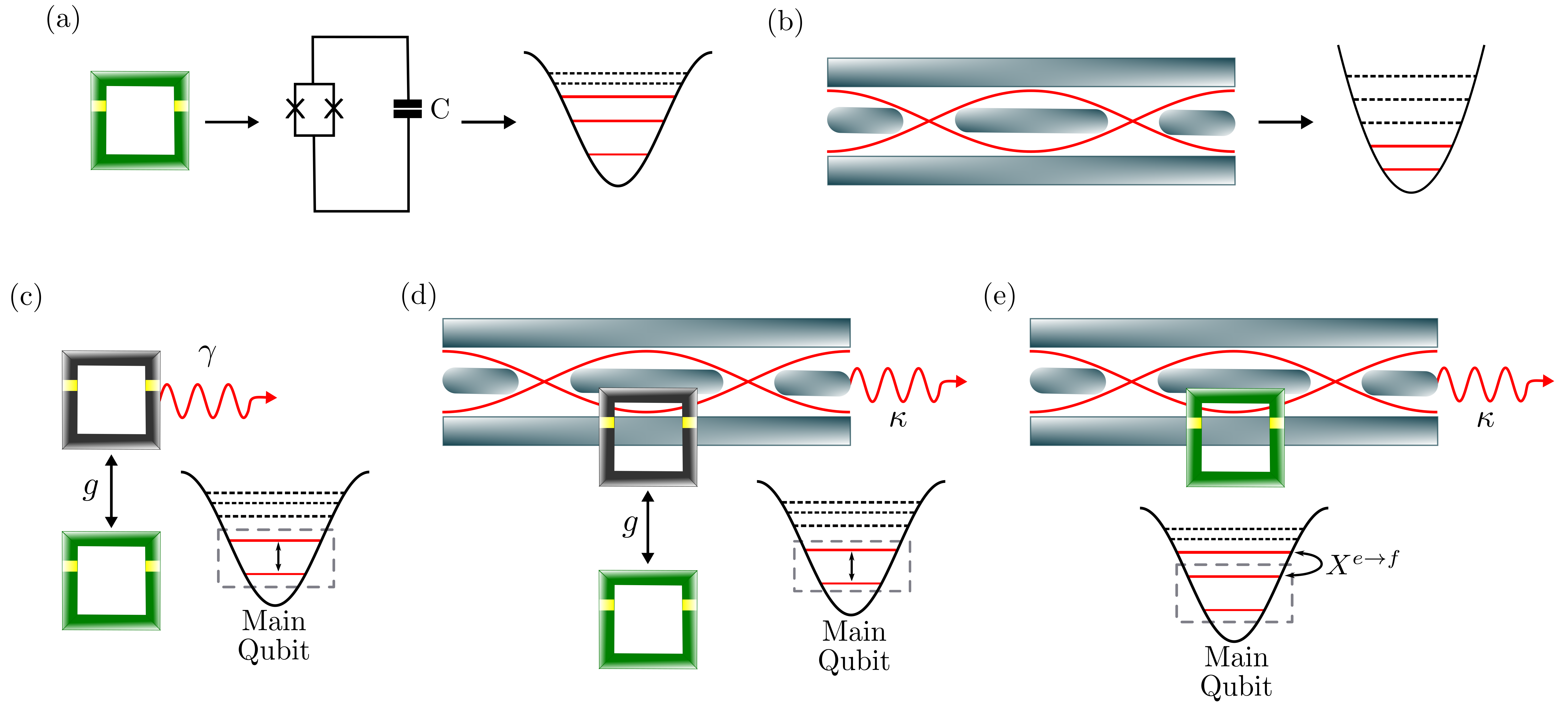
Looking at the fastest way to reset systems, we analyze here two configurations that use dissipative effects to reset the qubit. In addition, we optimize the reset model from Ref. Egger et al. (2018) and compare its results with the ones achieved with the two new models. The different experimental setups, which will be explored throughout this manuscript, are indicated in Fig. 1(a)-(e). The first configuration studied here, Fig. 1(c), is a work qubit (named as main qubit) coupled directly to a second highly dissipative qubit (auxiliary qubit). In Refs. Basilewitsch et al. (2017); Fischer et al. (2019), it was used a similar model to study how to speed up the resetting and the purification of the system, but differently from the present work, the authors employed a tunable frequency qubit as the main system and considered the presence of correlations between the qubit and the environment. Also, in Basilewitsch et al. (2021), using a model similar to the previous one, it was studied how the increasing of the size of the ancilla qubit Hilbert space affects the resetting time. In the second configuration, Fig. 1(d), the main qubit is coupled to a second one, which is then coupled to a dissipative cavity mode. In Basilewitsch et al. (2019) it was also used two auxiliary components as in our model, but, once again, it was considered tunable frequencies in order to maximize the efficiency of the resetting. Finally, in the third experimental setup investigated here we take into account the multilevel structure of a superconducting device, i.e., in addition to the two levels that work out as the main qubit, an auxiliary third level is considered, which is used to couple the quantum device to a dissipative bosonic field mode, Fig. 1(e). This resetting mechanism is quite interesting for its simplicity and efficiency and it was studied before in Refs. Magnard et al. (2018); Egger et al. (2018), where, in the both of them, the authors employed a Jaynes-Cummings-type interaction to reset the system, but with different approaches, which made the resetting time achieved in the latter to be more than twice as fast as in the former. Still concerning the last configuration, besides of saving space in the quantum computer by eliminating the need for a auxiliary qubit, this scheme can be applied to fixed frequency qubit architectures, as the case of the IBM systems in Refs. Egger et al. (2018); IBM .
In this work we carry out a numerical analysis of the main qubit dynamics for the three configurations cited above and then we perform an optimization for each setup, searching for the set of parameters that makes the resetting process faster. To present our results, this manuscript is organized as follows: Section II introduces the three models shown in Fig. 1 and it describes two different approaches that will be used in the information erasing, which are: (i) the pulsed and (ii) the steady-state approaches. In Section III, it is shown the parameters that optimize the resetting for each model using these two approaches and it is discussed their experimental feasibility. Finally, Section IV presents our conclusions.
II Description of the models
To model the resetting mechanism we resort to the open quantum system treatment, working in a regime where the interaction energy between the subsystems that make up our setup is much smaller than the free energy of the subsystems themselves. On the other hand, the coupling strengths between the subsystems can be either stronger or weaker than the their dissipation rates, usually named as strong or weak coupling regimes, respectively. In these regimes, and assuming Born and Markov approximations, the dynamics of the system is governed by the master equation () Breuer and Petruccione (2002)
| (1) |
in which the Hamiltonian describes the system coupled to the auxiliary components, is the density operator of the composed setup, describes the dissipation in a quantum bosonic mode and describes the energy loss of an ancilla qubit. The decay rate of the auxiliary qubit and the bosonic mode are given by and , respectively, () is the Pauli raising (lowering) operator for the auxiliary qubit and () is the annihilation (creation) operator for the dissipative field mode. Since Eq. (1) is a general equation, it can describe the three configurations studied here, therefore the Hamiltonian and the presence of the dissipation operators in this equation will depend on the model, which will be detailed at the moment when we formally introduce each setup. Once we know the configuration that will be analyzed, we are able to replace in Eq. (1) the corresponding Hamiltonian that will rule the dynamics in each case and the respective dissipation operators of the auxiliary components and, then, proceeding with the simulations. At this point, one can notice the lack of dissipation operators for the main qubit, our system. In this paper, its absence is a reasonable assumption because quantum computing requires qubits with negligible decay rates, thus we are considering the main qubit as a non-dissipative system, hence the entire process of energy dissipation takes place via auxiliary components.
The three configurations for resetting the main qubit that we are going to study here are pictorially represented in Fig.1. In panel (a) we represent a superconducting device whose the two lower levels represent our main qubit. In panel (b) we represent the waveguide, which works as a dissipative cavity mode and it is described by a harmonic potential. In panel (c) we represent the two-qubit model, where the main qubit is coupled to an auxiliary dissipative one. In panel (d), we represent the main qubit coupled to a second one, which in turn is coupled to a dissipative bosonic mode. Finally, in panel (e), we display the system studied in Ref. Egger et al. (2018), which is composed by the main qubit and the auxiliary third level that is coupled to a dissipative cavity mode.
To start, let us introduce the first configuration, as shown in Fig. 1(c), called here by two-qubit model. This setup contains the main qubit coupled to a dissipative auxiliary one and has the advantage of being very simple and compact, saving space in a quantum computer. Also, the auxiliary qubit does not need to be fully controllable, since we do not perform operations over its states. On the other hand, as it can emit in any direction, its dissipation could affect the work qubits in a huge quantum computer, depending on the configuration. Besides, to avoid extra noise and undesired dissipation in the main qubit during the execution of a given quantum process, we must be able to turn on and off its interaction with the auxiliary qubit. This can be done assuming that the auxiliary qubit is frequency tunable, being most of the time very far from resonance with the main qubit. Then, to implement the reset process we turn its frequency on resonance with the main qubit, which can be done very quickly, below one nanosecond HU (2023), so we are disregarding this time in our analyses. Thus, during the reset process we can consider these qubits as resonant ones, whose Hamiltonian in the interaction picture is given by
| (2) |
where is the coupling strength between the main () and the auxiliary () qubits, and is the transition level operator from level to level () for qubit (,).
The second configuration analyzed here, named two qubits-cavity model, is shown in Fig. 1(d) and it is composed by the main qubit coupled to a second non-dissipative and tunable (as in the previous case) auxiliary qubit, which in turn is coupled to a dissipative cavity mode field whose dissipation rate is . In this model, when turning the auxiliary qubit on resonance with the main one and the cavity mode, we end up with the coupling strength between the two qubits, which can be different from the coupling strength between the auxiliary qubit and the cavity mode field. In this case, in the interaction picture, the Hamiltonian reads
| (3) |
where ( is the annihilation (creation) operator for the mode and, again, and stand for main and auxiliary qubits, respectively. This model requires more elements and space, but the dissipative mode can direct the dissipated energy, thereby avoiding disturbances to neighboring working qubits in a quantum computer.
The Fig. 1(e) shows the third model studied here, where the main qubit has an auxiliary level that is coupled to a dissipative bosonic mode. This configuration is named here as IBM model since it was studied by IBM researchers Ref. Pechal et al. (2014); Egger et al. (2018); Zeytinoğlu et al. (2015). The Hamiltonian that describes this setup, in the rotating frame of the driving field, which has a frequency , is
| (4) |
where () is the cavity-mode field annihilation (creation) operator as in the previous case, () is the annihilation (creation) operator of the main system, now considered as a multilevel structure, is the coupling strength between the cavity and the system, is the time-dependent amplitude of the microwave field that drives the qubit, , , with () being the transition frequency of the cavity mode (qubit) and, at last, is the anharmonicity that modifies the frequency transition between the excited state of the qubit and the auxiliary level , such that .
In contrast to the first two configurations cited before, in which the reset processes start when the main qubit begins its interaction with the other components, the resetting in IBM model occurs in two steps: (1) the state population initially in is transferred by an electromagnetic pulse to the ancilla level ; (2) then the population of the state is transferred to a dissipative cavity mode via its coupling to the transition with the help of a driving field with amplitude and frequency . In the first step, the time to transfer the population depends on the intensity of the pulse, i.e., its Rabi frequency, such that as higher the Rabi frequencies is, as smaller the time to reach the desired final state. However we cannot increase the intensity indiscriminately, since levels higher than could be populated, in a way that would make the step (2), and consequently the entire reset process, ineffective. To avoid this loss of efficiency, we will consider here the same pulse that was used in Ref. Egger et al. (2018) to transfer the population to the auxiliary level, which makes the first step of the approach finishes in . Hence, in order to speed up the resetting for this configuration, we will focus on optimizing the second step by searching the parameters that dissipate the energy faster.
Besides the three configurations, we also deal with two approaches. In the first, here called the steady-state approach, the reset occurs when the system reaches the ground state in a stable way. In the second approach, which we will call by the pulsed approach following Ref. Egger et al. (2018), the reset occurs when the interaction dynamics takes the main qubit to the ground state for the first time and, exactly at that moment, the pulse is turned off and the information is erased. The IBM model was developed based only on a pulsed approach. As explained before, the model studied in Ref. Egger et al. (2018) involved two steps. On the other hand, for the other two models studied here, the pulsed approach happens just in one step, since we do not have to transfer the population to another level as in the IBM model. Hence, for the other two models, in the pulsed approach the reset process starts when the main qubit is coupled to the auxiliary dissipative systems and it is finished when the required ground state population is achieved for the first time. The time to couple (decouple) the main qubit to (from) the auxiliary components is negligible in the analyses of the reset time, as discussed above.
Now, given the models in Fig. 1, we can proceed with the calculations. For comparison purposes, in all simulations we considered the main qubit initially in the excited state, while all the other auxiliary components were considered to be in their respective ground states. In fact, considering the auxiliary components to be in their ground states is a realistic assumption according to Chu et al. (2022), since, following their parameters for the mode transition frequency and temperature, the fidelity between the thermal state and ideal ground state is above , which is a small error in the state preparation. Next, we solve Eq. (1) numerically in Python using the QuTip toolbox Johansson et al. (2012, 2013) considering the particularities of each model and analyze the dynamics of the ground state population of the main qubit. The study of this property of the main system allows us to determine how and when the reset process must happen.
III Results and discussions
As we are looking at the resetting process, the baseline studied here will be the ground state population of the main qubit. In this way, for the steady-state approach, we consider the reset process performed when the population of the main qubit reaches the minimum value without recurring anymore. Usually, to reset properly, quantum computers require a much higher population in the ground state. However, we decided to choose this value in order to perform a fair comparison of our results with the ones presented in Egger et al. (2018), which use this population value for the ground state. In the same way, for the pulsed reset approach, we will consider that the process ends when the population of the main qubit reaches the minimum value of for the first time, which is the instant when the pulse must be turned off. Still, the required time to reach the desired ground state population, the reset time, is named here .
|
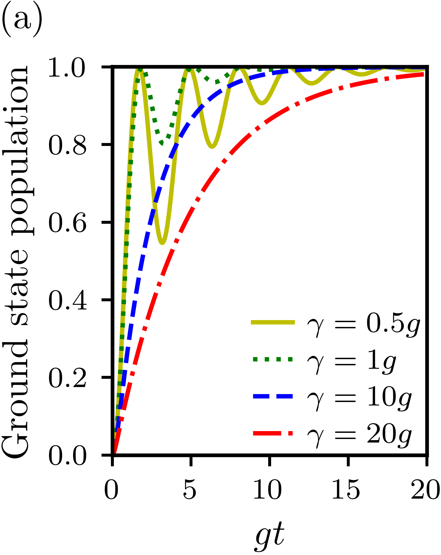
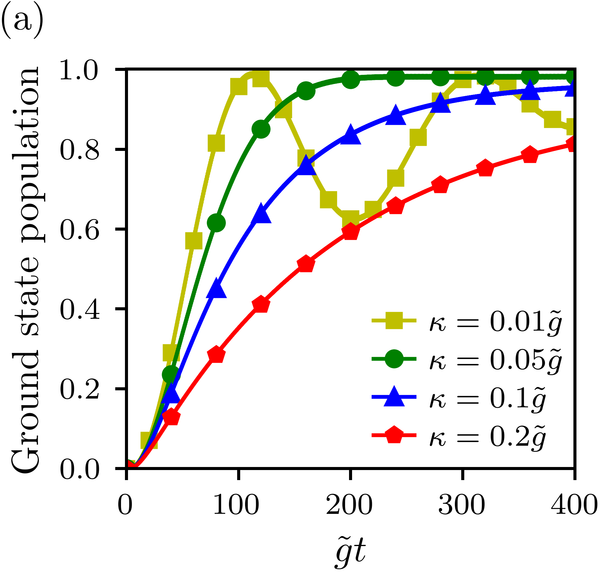
Now, to study the reset protocol for the models presented in Fig.1(c)-(e), let us start considering the two-qubit model, Fig. 1(c), where we analyzed the dynamics of the ground state population of the main qubit for different values of the dissipation rate of the auxiliary qubit, given by . For this configuration, Fig. 2(a) shows the ground state population versus . Looking at this panel, when considering the steady-state approach, we can notice that the best value is . Unlike what would be expected, as the dissipation rate is increased regarding to the coupling strength between the two qubits, the system reset becomes ineffective, i.e., the resetting will take longer to occur, e.g., see the curve for . Conversely, still in the same approach, if the dissipation rate is too small, it will take too long for the reset process to stabilize and finish, although the first peak of the dynamics occurs earlier, what is a good fact for the pulsed approach, as it happens for either or for instance.
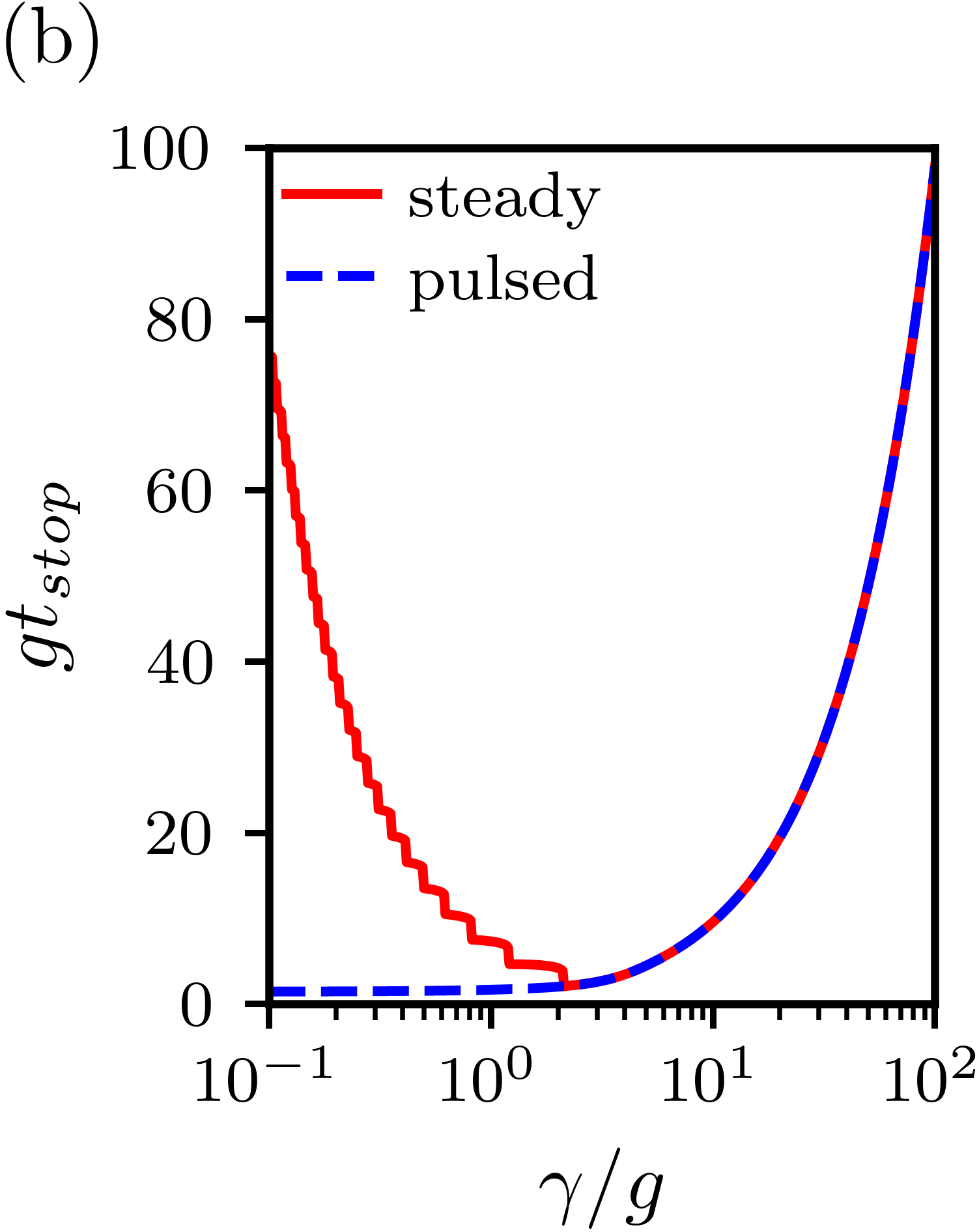
In Fig. 2(b) it is shown the time as a function of for the two reset approaches. Starting with the pulsed approach, one can note that for values of smaller than , approximately, the does not depend on the decay rate of the auxiliary qubit, being the best times close to . On the other hand, when considering the steady-state approach, from Fig. 2(a) we see that there is an optimum value for the reset time. From Fig. 2(b), we numerically find that this optimum value () occurs for . For values greater than this ratio, the reset process is ineffective since the time increases as increases. Still, for , the time also increases as the ratio decreases. For instance, if we now consider the minimum ground state population of , as required to perform realistic quantum computing, the best reset times achieved are and , for the pulsed and steady-state approaches respectively, where the parameter that optimizes the reset time for the latter approach is .
Still regarding the two-qubit model, one can notice in Fig. 2(a) that the dynamics for greater values of do not oscillate, while the dynamics for smaller values of do oscillate, as one can see from comparing the curves for and . These oscillations for the smaller values of , which arise from the energy flux between the qubits, are the origin of the discontinuities existing in Fig. 2(b) in the curve for the steady-state approach. In fact, in the beginning of the dynamics, the energy stored in the main qubit flows to the auxiliary qubit, which has a weak decay, i.e., has the same magnitude or it is smaller than the coupling strength . Then, due to its small dissipation rate, the energy that is transferred to the auxiliary qubit is able to flow back to the main one before it is completely dissipated, hence, the ground state population of the main qubit keeps recurring. This energy exchange between the qubits continues to occur and several oscillations in the dynamics of the ground state population take place until the reset process is over. It is worth noting that the number of oscillations depends on the value of , i.e., the more oscillations occurs, the longer the reset time is, and vice-versa.
|
|
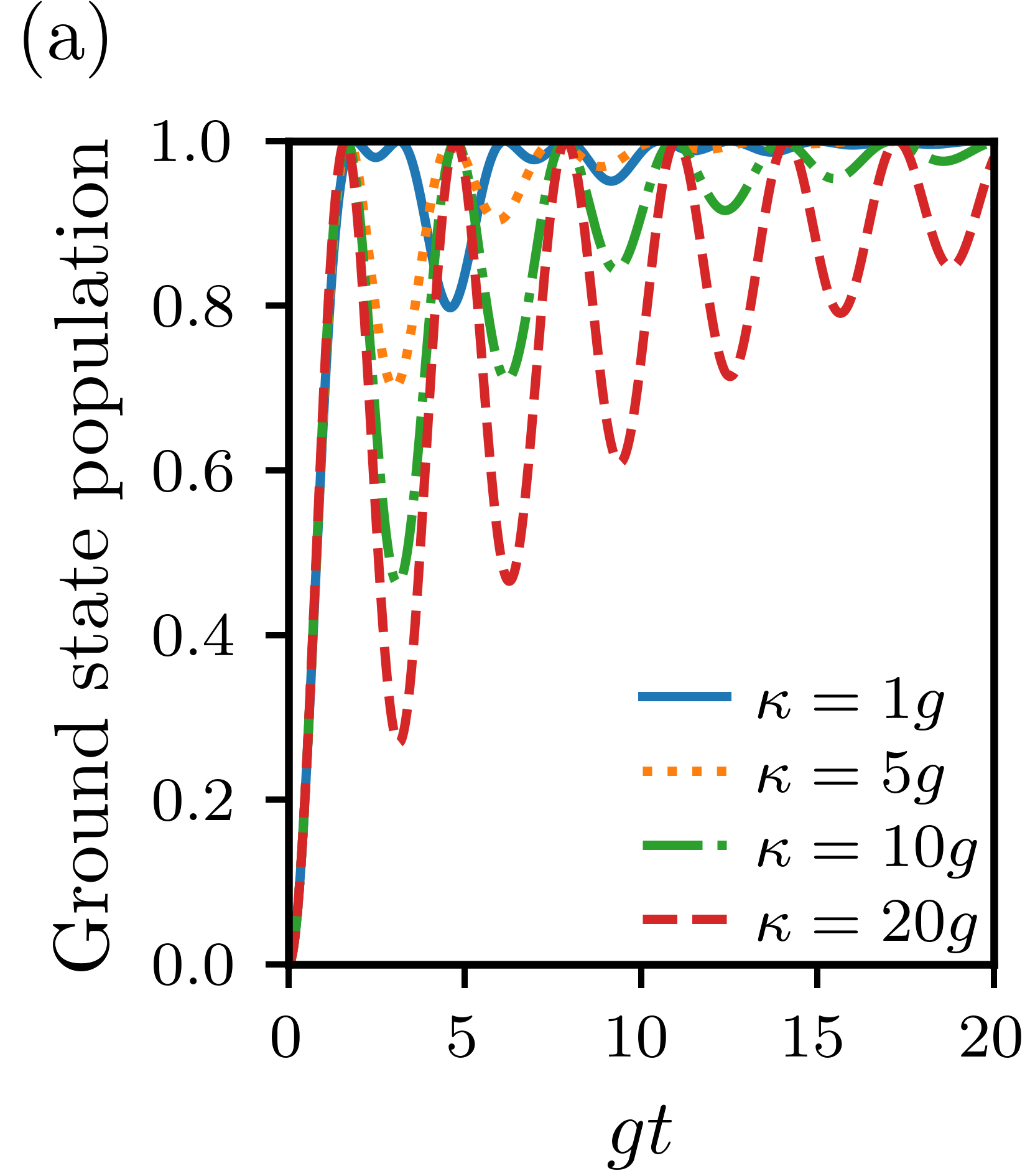
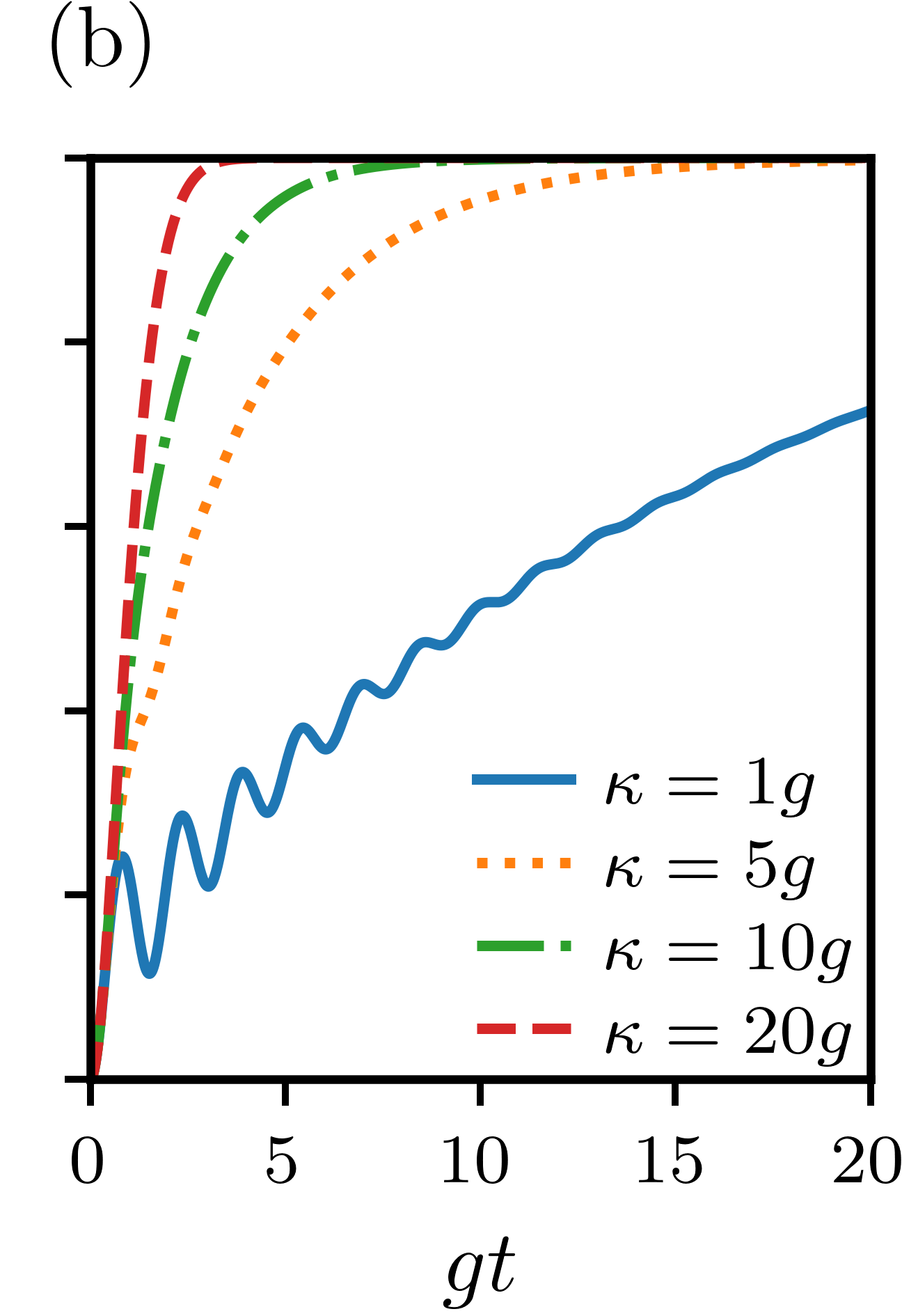
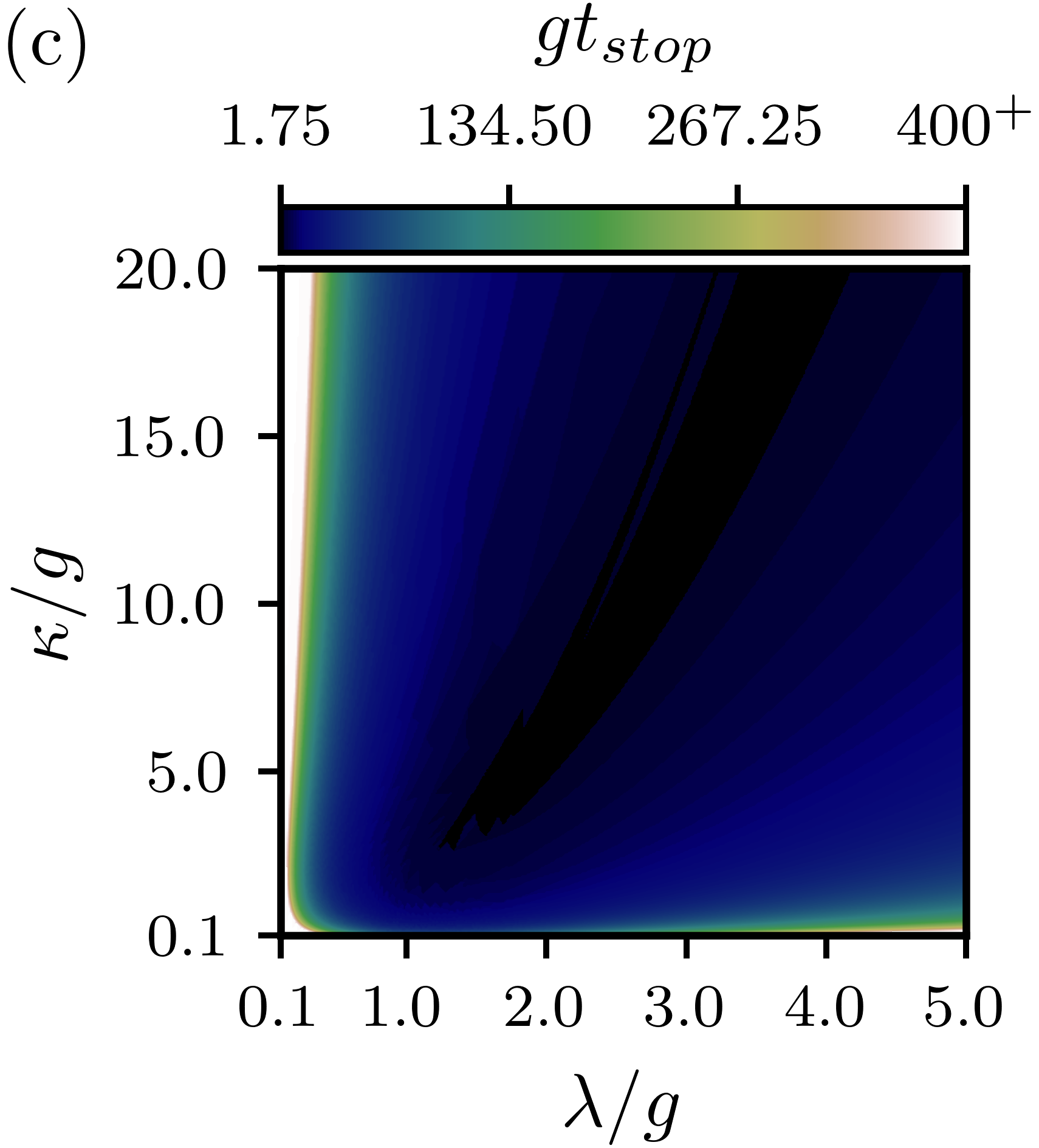
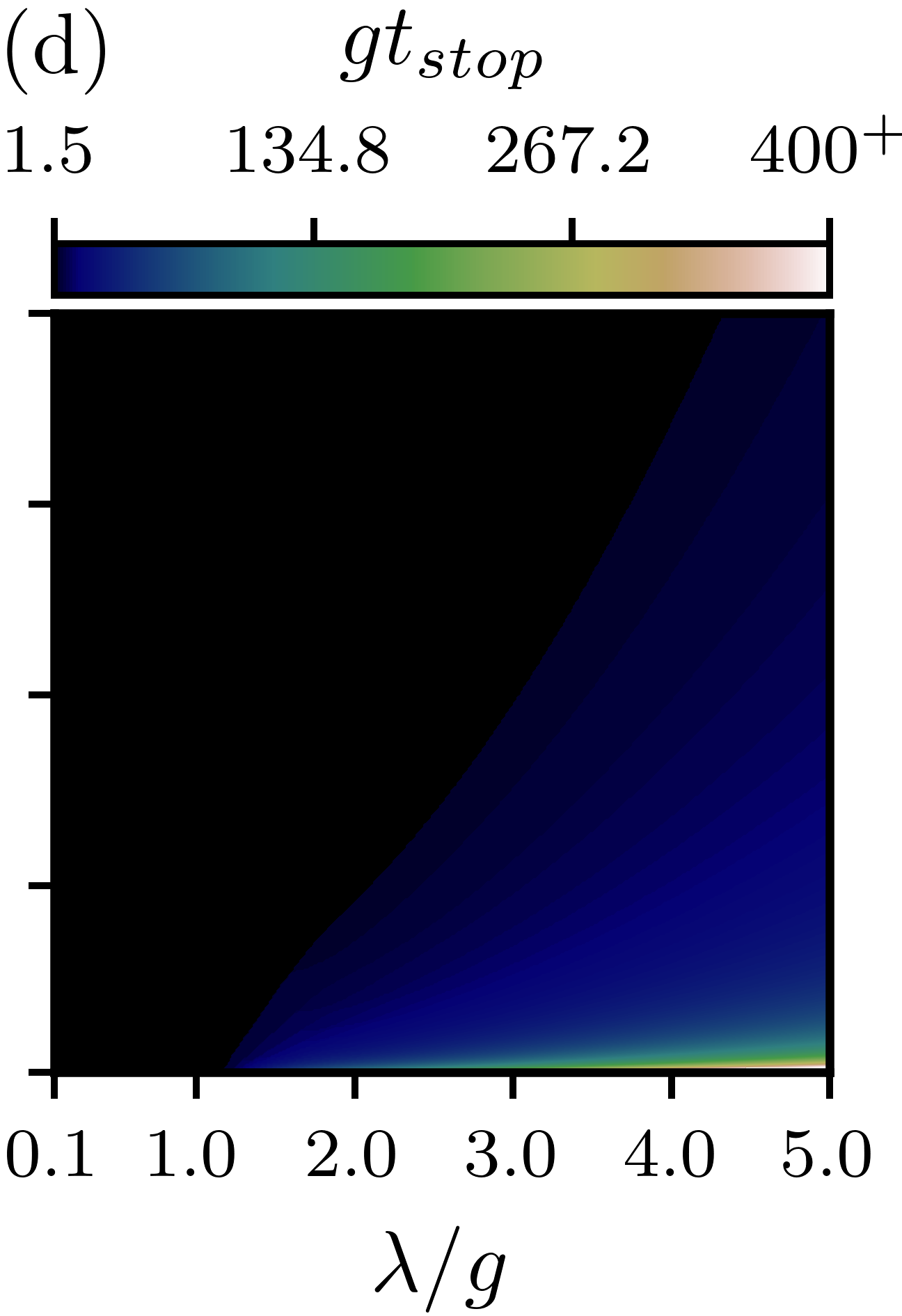
For the two qubits-cavity model, represented in Fig. 1(d), we have three parameters, two from the Hamiltonian of Eq. (3) and one from the dissipation operator, which are respectively: the coupling strength between the two qubits, the coupling strength between the auxiliary qubit and the cavity mode field; and the damping rate of the electromagnetic (EM) field mode. Thus, by fixing the coupling as before, there will remain two parameters to be adjusted in order to optimize the resetting process. The results for this case are shown in Fig. 3, where we plot in the upper panels the dynamics of the ground state population of the main qubit as a function of the dimensionless time for , Fig. 3(a), and , Fig. 3(b), in both cases considering different values for – see legend. Looking at these two panels, once again the previous discussion about steady-state population can be made, since there are values of and for which the dynamics either oscillates and takes a long time to stabilize with a ground state population above the predefined bound, or it does not fluctuate, but still takes time to reach the desired bound. Hence, for this approach, once more we can infer that there is a optimum reset time. On the other hand, for the pulsed approach, an initial analysis reveals that the ratio between and appears to determine when the reset occurs, since one can see from panel 3(a) – where we have the smaller value of () – that for all values of the dynamics reach their first peaks fast whereas in panel 3(b) – where we have the bigger value of () – only the dynamics for the bigger values of reach their peaks fast.
Turning now to the optimizations, the panel 3(c) shows the as a function of and for the steady-state approach. From this panel we can see that the best reset times – close to – are found in a narrow range of the parameters and only. One can also note that there are blank areas in this panel, which represent the set of parameters for which it is not possible to reach the minimum ground state population of the main qubit () in a stable way and within the maximum stipulated time in our simulations (). For the pulsed approach, similar results can be seen in Fig. 3(d), but now the set of parameters with the best resetting times is larger, being the best times around . On balance, for the first two configurations (two-qubit model and two qubits-cavity model), we found that the best times for the pulsed approach are slightly shorter than the best times for the steady-state approach. In contrast, the disadvantage of former as compared to the latter approach is the need for a high level of precision in controlling the duration of the time pulse. In fact, since in the pulsed approach we have to stop the time evolution in a very precise time, we need an experimental precision of the order of , meaning that even a small inaccuracy in the stopping time of the dynamics will cause the system state to be far from the ground state, thus introducing errors and making the resetting process ineffective. If we consider, as before, the minimum ground state population of , the best reset times do not change in both approaches. The changes in the results happen just in the set of parameters that reaches the required population, i.e., the same best reset times are achieved, but a smaller set of parameters achieves the required population during these best times.
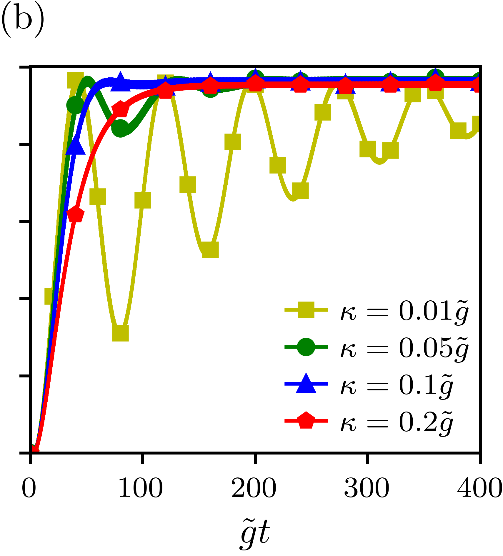
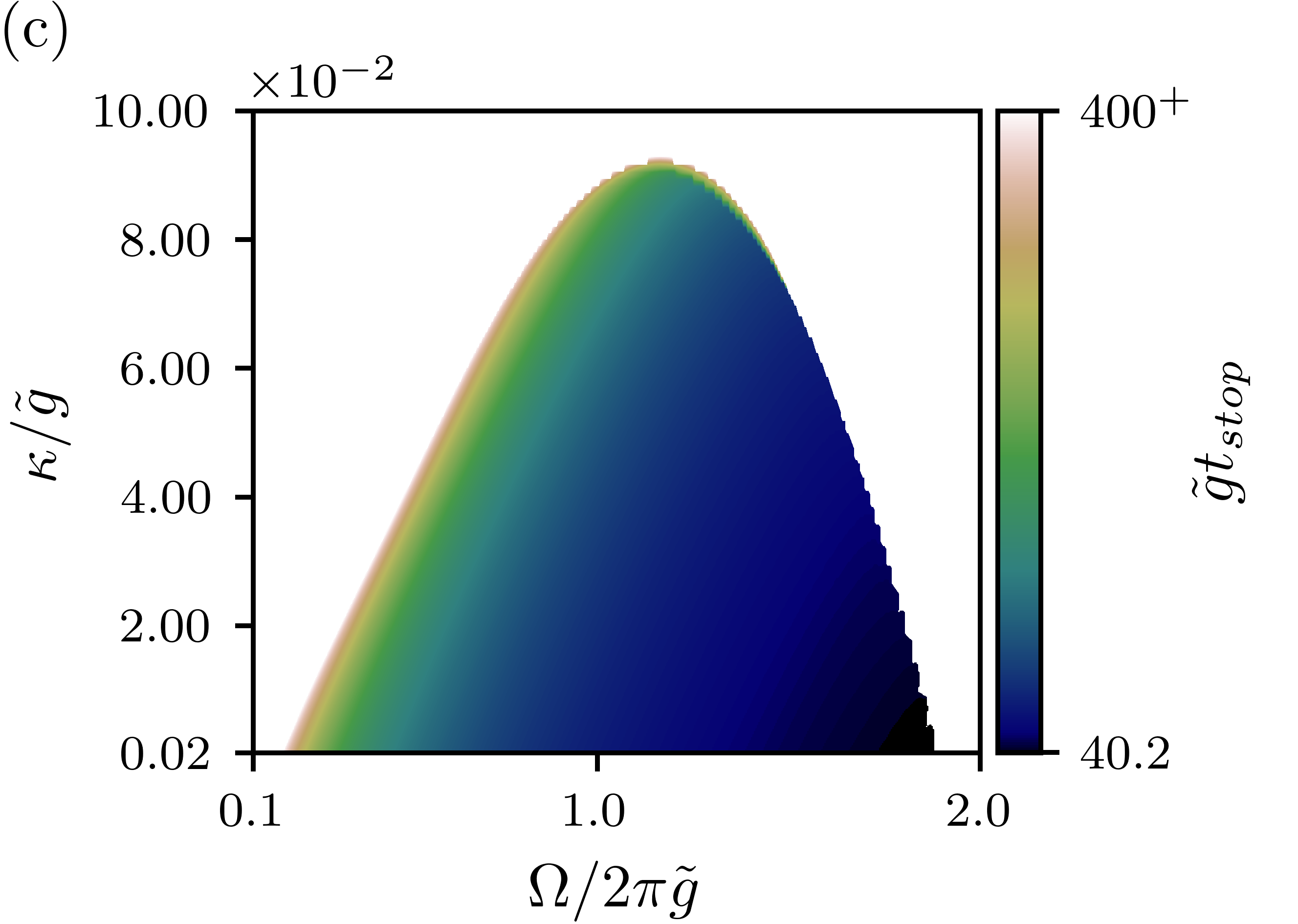
|
The IBM model Egger et al. (2018) is the last configuration studied here. Again, since this model was developed aiming the pulsed approach, we just searched for its optimization, i.e., we did not consider the steady-state approach for this model. As said before, this model occurs in two steps. Firstly the population of the excited state is transferred to the auxiliary state via auxiliary pulse. Since the intensity of the pulse modifies either the time spent in this step and the possible maximum transferred population, we consider here the same pulse that was used in Egger et al. (2018), which takes to transfer the population to the state , approximately. Once the main system is in the state , the second step starts coupling the system to the dissipative cavity mode in order to bring it to the desired ground state. Hence, to optimize the second step of the approach, and consequently the entire process, we searched for the parameters that make the dissipative dynamics of the transition faster.
Proceeding as in the previous cases, in Figs. 4(a)-(b) we show the dynamics of the ground state population of the main qubit as a function of the dimensionless time . Remembering we are considering the pulsed approach only, from Fig. 4(a) we can see that, for a given value of , very large values of do not improve the resetting process, i.e., the higher the longer the reset will take. However, by increasing , as shown Fig. 4(b), we can notice that the reset becomes faster, once, as we can see from the comparison of the two panels, for a fixed , the first peak of the ground state population happens earlier for .
Looking for the optimization process, panel 4(c) shows two regions. The colored region shows the as a function of and . Note from this figure that the shortest time spent in the second step of the reset is ( , when considering MHz as in Egger et al. (2018)), which results in a total resetting time, i.e., considering the two steps of the approach, of , thus decreasing almost the resetting time, as compared to the result achieved in Ref. Egger et al. (2018), that is . The other region is the blank area, which represents again the set of parameters whose resetting times are longer than the limit of . For these parameters the resetting delays due to one of following reasons: (i) the dynamics for a given and naturally take to long – this behavior happens for small values of mostly, e.g., see the curve for at Fig. 4(a); or (ii) as said before, the efficiency of the transition depends on the intensity of the pulse, therefore as the value of increases, the smaller the efficiency of this transition is, so that the interaction between the qubit and the cavity has to be kept for longer until the bound population of is reached, and occasionally this time surpasses the predefined limit of .
An important question that could rise is the impact for quantum computing of the lossy effects induced by the auxiliary systems in the dynamics, because they can harm the performance of the device. When the main qubit is not working, some methods can be applied to reduce the crosstalk due to the interaction of the main qubit, and consequently the reset components, with the other working qubits. For example, following Xu et al. (2020) and Hu et al. (2023), the couplers present in the architecture of the computer can be used to reduce such crosstalk and even effectively cancel the interactions between two specific components, which are the main qubit and other working qubits present in the architecture of the quantum device. On the other hand, when the main qubit is actively involved in calculation tasks, it is possible to set the frequency of the auxiliary qubit far off the resonance, which implies in a large detuning between the main and auxiliary qubits that cancels the interaction between them. Therefore, either during the resetting process and the computing step, it is possible to avoid the undesired crosstalk and strong induced decays of the qubits.
For instance, consider the coupling strengths close to the ones in Ref. Hu et al. (2023), which are around MHz. The Purcell decay time for the two-qubit model, Fig. 1(c), is expressed as , with being the detuning between the main and the auxiliary qubits during the computing step Houck et al. (2008). Thus, assuming that the effective decay induced by the auxiliary qubit is of the order of the natural decay of the main qubit, that is of the order of Egger et al. (2018); Burnett et al. (2019), we note that detunings of the order of GHz up to GHz will be required. For instance, for the steady-state approach, it is possible to achieve using detunings close to GHz and sets of parameters () that result in reset times of approximately. On the other hand, for the pulsed approach, it is possible to achieve considering detunings smaller than GHz, even if the optimum sets of parameters is used (). Noteworthy, the required detunings are feasible to guarantee these reasonable decay times Hutchings et al. (2017); Houck et al. (2008); Bronn et al. (2015). Now, for the two qubits-cavity model, Fig. 1(d), it is necessary taking into account the effective decay rate of the component coupled to the main qubit. In the second model studied here, the auxiliary qubit has an effective decay rate, due to its resonant coupling to the dissipative cavity mode, which is given by Prado et al. (2009); de Assis et al. (2023), such that the Purcell decay time of the main qubit has to be computed as . In this context, it is possible to achieve the same Purcell decay times from before, , considering for the pulsed approach detunings of GHz approximately and the optimum sets of parameters, while the steady-state approach requires detunings of GHz approximately and sets of parameters that result in reset times smaller than . Additionally, if one considers a coupling strength similar to the one used in the IBM paper Egger et al. (2018), which is MHz, it is possible to achieve Purcell decay times around considering detunings smaller than GHz, which are still feasible, and sets of parameters that result in reset times of approximately.
IV Conclusion
In this work we have analyzed the optimization of the resetting time of superconducting qubits in three models: (i) two-qubit model, where the main qubit is coupled to a second dissipative one, (ii) two qubits-cavity model, composed by two interacting qubits with coupling strength , one being the main qubit and the other being the auxiliary qubit, which is coupled to a dissipative cavity mode, and (iii) IBM model, where a qubit and an auxiliary level are coupled to a dissipative bosonic mode. To study the resetting times in the first two models, which are analyzed here for the first time, we consider two different situations: the steady-state and the pulsed approaches. The model (iii), which was designed to operate with the pulsed approach only, was introduced first in Ref. Egger et al. (2018). After the optimizations we were able to reduce the resetting time achieved in Egger et al. (2018) at about for their model, as they achieved for the resetting time and here, using the same coupling strength MHz, we could achieve the resetting time of . Furthermore, we note that this best resetting time of the IBM model is two orders of magnitude larger than the best resetting times of the two other models analyzed here, which are lesser than , where we are considering again the same coupling strength as before. Concerning the models (i) and (ii), in both of them the pulsed approach is slightly faster than the steady-state approach. However, it is necessary to keep in mind a possible disadvantage of the first approach compared to the latter, as pulsed approach requires high experimental accuracy in its execution to control the system dynamics. Finally, it is important to notice that one could argue that it could be possible to achieve shorter reset times in practice just employing even stronger couplings. However, the couplings between the subsystems can not be increased arbitrarily, once we could end up in the ultra-strong or deep-strong coupling regimes Yoshihara et al. (2017); Mercurio et al. (2022), which are the regimes in which the interaction energies between the subsystems are of the same order or even higher than the free energies of the subsystems. In these regimes the ground state of the system is an entangled state between the subsystems Shitara et al. (2021); Beaudoin et al. (2011), with virtual photons that make it difficult to prepare the main qubit in its ground state alone.
Acknowledgments
We acknowledge financial support from the Brazilian agencies: Coordenação de Aperfeiçoamento de Pessoal de Nível Superior (CAPES), Financial code 001, National Council for Scientific and Technological Development (CNPq), Grants No. 311612/2021-0 and 301500/2018-5, São Paulo Research Foundation (FAPESP) Grants No. 2019/11999-5, 2019/13143-0, 2022/10218-2, and No. 2021/04672-0, and Goiás State Research Support Foundation (FAPEG). This work was performed as part of the Brazilian National Institute of Science and Technology for Quantum Information (INCT-IQ/CNPq) Grant No. 465469/2014-0.
References
- Kleißler et al. (2018) F. Kleißler, A. Lazariev, and S. Arroyo-Camejo, npj Quantum Information 4 (2018), 10.1038/s41534-018-0098-7.
- Huang et al. (2019) W. Huang, C. H. Yang, K. W. Chan, T. Tanttu, B. Hensen, R. C. C. Leon, M. A. Fogarty, J. C. C. Hwang, F. E. Hudson, K. M. Itoh, A. Morello, A. Laucht, and A. S. Dzurak, Nature 569, 532 (2019).
- Fowler et al. (2012) A. G. Fowler, M. Mariantoni, J. M. Martinis, and A. N. Cleland, Physical Review A 86 (2012), 10.1103/physreva.86.032324.
- Dennis et al. (2002) E. Dennis, A. Kitaev, A. Landahl, and J. Preskill, Journal of Mathematical Physics 43, 4452 (2002).
- Gottesman (1997) D. E. Gottesman, Stabilizer Codes and Quantum Error Correction, Ph.D. thesis (1997).
- Wang et al. (2003) C. Wang, J. Harrington, and J. Preskill, Annals of Physics 303, 31 (2003).
- Xin et al. (2020) T. Xin, S. Wei, J. Cui, J. Xiao, I. n. Arrazola, L. Lamata, X. Kong, D. Lu, E. Solano, and G. Long, Phys. Rev. A 101, 032307 (2020).
- Egger et al. (2018) D. Egger, M. Werninghaus, M. Ganzhorn, G. Salis, A. Fuhrer, P. Müller, and S. Filipp, Phys. Rev. Applied 10, 044030 (2018).
- Barrett et al. (2013) S. Barrett, K. Hammerer, S. Harrison, T. E. Northup, and T. J. Osborne, Physical Review Letters 110 (2013), 10.1103/physrevlett.110.090501.
- Ristè et al. (2012) D. Ristè, J. G. van Leeuwen, H.-S. Ku, K. W. Lehnert, and L. DiCarlo, Physical Review Letters 109 (2012), 10.1103/physrevlett.109.050507.
- Blais et al. (2004) A. Blais, R.-S. Huang, A. Wallraff, S. M. Girvin, and R. J. Schoelkopf, Physical Review A 69 (2004), 10.1103/physreva.69.062320.
- Wallraff et al. (2004) A. Wallraff, D. I. Schuster, A. Blais, L. Frunzio, R.-S. Huang, J. Majer, S. Kumar, S. M. Girvin, and R. J. Schoelkopf, Nature 431, 162 (2004).
- Reed et al. (2010) M. D. Reed, B. R. Johnson, A. A. Houck, L. DiCarlo, J. M. Chow, D. I. Schuster, L. Frunzio, and R. J. Schoelkopf, Applied Physics Letters 96, 203110 (2010).
- Tuorila et al. (2017) J. Tuorila, M. Partanen, T. Ala-Nissila, and M. Möttönen, npj Quantum Information 3 (2017), 10.1038/s41534-017-0027-1.
- Tuorila et al. (2019) J. Tuorila, J. Stockburger, T. Ala-Nissila, J. Ankerhold, and M. Möttönen, Physical Review Research 1 (2019), 10.1103/physrevresearch.1.013004.
- Chen et al. (2021) T. Chen, L. Wan, J. Qiu, H. Peng, J. Lu, and Y. Yan, Journal of Physics B: Atomic, Molecular and Optical Physics 54, 135503 (2021).
- Basilewitsch et al. (2017) D. Basilewitsch, R. Schmidt, D. Sugny, S. Maniscalco, and C. P. Koch, New Journal of Physics 19, 113042 (2017).
- Fischer et al. (2019) J. Fischer, D. Basilewitsch, C. P. Koch, and D. Sugny, Physical Review A 99 (2019), 10.1103/physreva.99.033410.
- Basilewitsch et al. (2021) D. Basilewitsch, J. Fischer, D. M. Reich, D. Sugny, and C. P. Koch, Physical Review Research 3 (2021), 10.1103/physrevresearch.3.013110.
- Basilewitsch et al. (2019) D. Basilewitsch, F. Cosco, N. L. Gullo, M. Möttönen, T. Ala-Nissilä, C. P. Koch, and S. Maniscalco, New Journal of Physics 21, 093054 (2019).
- Magnard et al. (2018) P. Magnard, P. Kurpiers, B. Royer, T. Walter, J.-C. Besse, S. Gasparinetti, M. Pechal, J. Heinsoo, S. Storz, A. Blais, and A. Wallraff, Physical Review Letters 121 (2018), 10.1103/physrevlett.121.060502.
- (22) IBM, “The quantum experience,” http://www.research.ibm.com/quantum/.
- Breuer and Petruccione (2002) H.-P. Breuer and F. Petruccione, The theory of open quantum systems (Oxford University Press on Demand, 2002).
- HU (2023) C. HU, Research Assistant Professor at Shenzhen Institute for Quantum Science and Engineering (Southern University of Science and Technology) (private communication, Aug. 10, 2023).
- Pechal et al. (2014) M. Pechal, L. Huthmacher, C. Eichler, S. Zeytinoğlu, A. Abdumalikov, S. Berger, A. Wallraff, and S. Filipp, Physical Review X 4 (2014), 10.1103/physrevx.4.041010.
- Zeytinoğlu et al. (2015) S. Zeytinoğlu, M. Pechal, S. Berger, A. A. Abdumalikov, A. Wallraff, and S. Filipp, Physical Review A 91 (2015), 10.1103/physreva.91.043846.
- Chu et al. (2022) J. Chu, X. He, Y. Zhou, J. Yuan, L. Zhang, Q. Guo, Y. Hai, Z. Han, C.-K. Hu, W. Huang, H. Jia, D. Jiao, S. Li, Y. Liu, Z. Ni, L. Nie, X. Pan, J. Qiu, W. Wei, W. Nuerbolati, Z. Yang, J. Zhang, Z. Zhang, W. Zou, Y. Chen, X. Deng, X. Deng, L. Hu, J. Li, S. Liu, Y. Lu, J. Niu, D. Tan, Y. Xu, T. Yan, Y. Zhong, F. Yan, X. Sun, and D. Yu, Nature Physics 19, 126 (2022).
- Johansson et al. (2012) J. Johansson, P. Nation, and F. Nori, Computer Physics Communications 183, 1760 (2012).
- Johansson et al. (2013) J. Johansson, P. Nation, and F. Nori, Computer Physics Communications 184, 1234 (2013).
- Xu et al. (2020) Y. Xu, J. Chu, J. Yuan, J. Qiu, Y. Zhou, L. Zhang, X. Tan, Y. Yu, S. Liu, J. Li, F. Yan, and D. Yu, Physical Review Letters 125 (2020), 10.1103/physrevlett.125.240503.
- Hu et al. (2023) C.-K. Hu, J. Yuan, B. A. Veloso, J. Qiu, Y. Zhou, L. Zhang, J. Chu, O. Nurbolat, L. Hu, J. Li, Y. Xu, Y. Zhong, S. Liu, F. Yan, D. Tan, R. Bachelard, A. C. Santos, C. Villas-Boas, and D. Yu, Physical Review Applied 20 (2023), 10.1103/physrevapplied.20.034072.
- Houck et al. (2008) A. A. Houck, J. A. Schreier, B. R. Johnson, J. M. Chow, J. Koch, J. M. Gambetta, D. I. Schuster, L. Frunzio, M. H. Devoret, S. M. Girvin, and R. J. Schoelkopf, Physical Review Letters 101 (2008), 10.1103/physrevlett.101.080502.
- Burnett et al. (2019) J. J. Burnett, A. Bengtsson, M. Scigliuzzo, D. Niepce, M. Kudra, P. Delsing, and J. Bylander, npj Quantum Information 5 (2019), 10.1038/s41534-019-0168-5.
- Hutchings et al. (2017) M. Hutchings, J. Hertzberg, Y. Liu, N. Bronn, G. Keefe, M. Brink, J. M. Chow, and B. Plourde, Physical Review Applied 8 (2017), 10.1103/physrevapplied.8.044003.
- Bronn et al. (2015) N. T. Bronn, E. Magesan, N. A. Masluk, J. M. Chow, J. M. Gambetta, and M. Steffen, IEEE Transactions on Applied Superconductivity 25, 1 (2015).
- Prado et al. (2009) F. O. Prado, E. I. Duzzioni, M. H. Y. Moussa, N. G. de Almeida, and C. J. Villas-Bôas, Physical Review Letters 102 (2009), 10.1103/physrevlett.102.073008.
- de Assis et al. (2023) R. J. de Assis, C. M. Diniz, N. G. de Almeida, and C. J. Villas-Bôas, Entropy 25 (2023), 10.3390/e25101430.
- Yoshihara et al. (2017) F. Yoshihara, T. Fuse, S. Ashhab, K. Kakuyanagi, S. Saito, and K. Semba, Physical Review A 95 (2017), 10.1103/physreva.95.053824.
- Mercurio et al. (2022) A. Mercurio, V. Macrì, C. Gustin, S. Hughes, S. Savasta, and F. Nori, Physical Review Research 4 (2022), 10.1103/physrevresearch.4.023048.
- Shitara et al. (2021) T. Shitara, M. Bamba, F. Yoshihara, T. Fuse, S. Ashhab, K. Semba, and K. Koshino, New Journal of Physics 23, 103009 (2021).
- Beaudoin et al. (2011) F. Beaudoin, J. M. Gambetta, and A. Blais, Physical Review A 84 (2011), 10.1103/physreva.84.043832.