Optics design and correction challenges for the high energy booster of FCC-ee
Institut de Recherche sur les lois
Fondamentales de l’Univers (IRFU)
Commissariat à l’énergie atomique
et aux énergies alternatives (CEA)
91191, Gif-sur-Yvette, France
antoine.chance@cea.fr
\And
Institut de Recherche sur les lois
Fondamentales de l’Univers (IRFU)
Commissariat à l’énergie atomique
et aux énergies alternatives (CEA)
91191, Gif-sur-Yvette, France
barbara.dalena@cea.fr
\AndTatiana Da Silva
Institut de Recherche sur les lois
Fondamentales de l’Univers (IRFU)
Commissariat à l’énergie atomique
et aux énergies alternatives (CEA)
91191, Gif-sur-Yvette, France
tatiana.dasilva@icloud.com
\AndAhmad Mashal
School of Particles and Accelerators
Institute for Research in
Fundamental Sciences (IPM)
P.O. Box 19395-5531, Tehran, Iran
ahmad.mashal@cern.ch
\And
University of Rome La Sapienza
NFN Roma1
Piazzale Aldo Moro, 5, 00185 Roma RM - Italy
mauro.migliorati@uniroma1.it
\And
Institut de Recherche sur les lois
Fondamentales de l’Univers (IRFU)
Commissariat à l’énergie atomique
et aux énergies alternatives (CEA)
91191, Gif-sur-Yvette, France
adnan.ghribi@cea.fr
\AndAli Rajabi
Deutsches Elektronen-Synchrotron (DESY)
Notkestr, 85, 22607 Hamburg, Germany
ali.rajabi@desy.de
\And
European Organization for Nuclear Research (CERN)
1211 Geneva 23 - Switzerland
frank.zimmermann@cern.fr
Abstract
One of the major upcoming challenges in particle physics is achieving precise measurements of the Z, W, and H bosons, as well as the top quark. To meet these targets, the next e+e- collider complex, FCC-ee, will need to achieve unprecedented luminosities. The FCC-IS European Study is investigating the feasibility of these challenges, with a cornerstone of the study being the design and optimization of the high-energy booster (HEB). This paper provides an update on the status of the HEB of FCC-ee in light of recent developments in the injector and collider survey, as well as an overview of ongoing work on longitudinal stability and design robustness in relation to field, alignment, and diagnostics errors. Constraints and effects related to the design frequency of the accelerating cavities, as well as collective effects, are also highlighted. Lastly, the paper presents an investigation into an alternative arcs cell design.
arXiv ICFA 2023 Newsletter pre-print
1 Introduction
FCC-ee is a double-ring lepton collider and the first operational stage of the integrated long-term FCC project. It is expected to serve as an electron-positron Higgs and electroweak factory, achieving the highest luminosities within 15 years. There are four operational modes defined for FCC-ee, which are referred to as , , , and . The beam properties, including energy, current, and emittance, vary for each mode. However, the short beam lifetime and the requirements for top-up injection are common features among them.
The High Energy Booster (HEB) is the final part of the injector complex, where particles with an energy of 20 GeV are injected into the HEB ring. The main criteria for the HEB lattice and its ramping cycle design are accelerating the particles up to the collision energy, adjusting beam properties for efficient top-up injection, and meeting filling time considerations.
Previous studies Benedikt et al. (2018) have shown that a single design could not satisfy the mentioned requirements for all energies. Therefore, two distinguished lattices have been designed, one for and modes and another for and modes. Preliminary results confirmed the lattices’ performance in the ideal case. However, in the realistic case, the HEB performance is affected by inevitable errors such as magnetic field imperfection and misalignment, instabilities raised from collective effects, and the behavior of particles during the ramping process. Hence, it is necessary to ensure the possibility of correcting destructive effects before finalizing the design.
The effects of magnetic multipole errors on lattice momentum acceptance and a first analytical estimation of emittance growth in the presence of intra-beam scattering have been previously reported Dalena et al. (2022). This paper is a status report on the aforementioned developments for the HEB design. The second section reports on the study of longitudinal phase space stability, while the third section details closed orbit correction strategies in the presence of misalignment errors. The fourth section shows the beginning of a joint effort for precise collective effects studies. Section six provides an update on the change in RF cavities frequencies with respect to the Conceptual Design Report and the corresponding RF budget. Finally, an alternative optics design under study is presented in the last section.
2 Optics stability
One of the ongoing tasks is to achieve sufficiently large Dynamic Aperture (DA) and Momentum Aperture (MA) for a phase advance lattice, designed for modes , and . By using a non-interleave sextupoles arrangement with 32 pairs of focusing sextupoles and 33 pairs of defocusing sextupoles in each arc, a considerably large dynamic aperture (in absence of the radiation and RF cavities) is obtained. Increasing the number of sextupole families to four and optimizing resonance driving terms enhances the DA, especially for off-momentum particles. The size of both the DA and MA is reduced when a 6D tracking procedure includes radiation effects and energy compensation at RF cavities has been performed. As a first step in resolving this issue, we investigate particles’ stability in the longitudinal phase space. A kilometer-scale bending radius of the dipole magnets, as well as the low value of dispersion function along them, makes the lattice’s momentum compaction factor to become very small. In this case, even a slight perturbation in momentum compaction could lead to instability in the longitudinal phase space. A variation in path length with momentum at higher order could be used to compute perturbation terms Wiedemann (2015) as Eq. \eqrefeq:deltal shows:
| (1) |
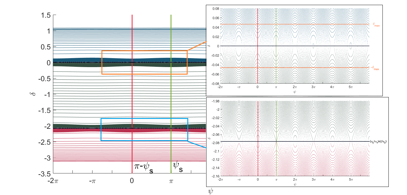
where is the nominal path length, the momentum compaction factor, the second order momentum compaction and the momentum independent term (see Wiedemann (2015) for more details). The extended form of the momentum compaction in the Hamiltonian reveals the existence of the secondary RF bucket in the longitudinal phase space. For certain condition which depends on perturbation terms and , these buckets could get close and interfere with each other. The buckets’ interference disturbs the longitudinal phase stability condition and reduces the momentum acceptance of the lattice. Moreover, the width of the RF buckets determines by the desired momentum acceptance and its required RF voltage. Hence, the stability criterion for the perturbation term as a function of desired momentum acceptance could be defined Wiedemann (2015) as in Eq. \eqrefeq:stability_condition: {align} α_1 &≤|ηc| (1-Γ)3/43(Δp/p0)desired Where Γ=4 ξα1ηc2 Tracking the on-axis particle within the momentum acceptance range of the ideal lattice gives us , , and ; so, the right hand side of Eq. \eqrefeq:stability_condition for desired momentum acceptance is equal to and the lattice meets this stability condition. The location of the primary and secondary RF buckets in the longitudinal phase space is shown in figure 1. It should be noted that the secondary RF buckets are situated at a considerable distance from the main buckets, and their influence on the particle dynamics can be disregarded.
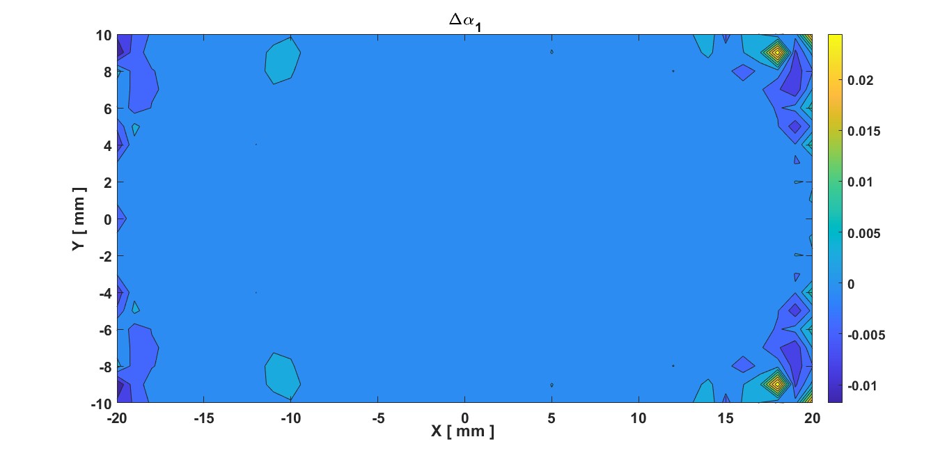
The initial amplitude of the particles could alter the value of , accordingly, the stability criteria for variation of has been defined in Wiedemann (2015) as : . To ensure the dynamic stability of the beam, the variation of within the range of [mm2] has been computed and its result is shown in figure 2. It could be concluded that the variation of for the defined range is far below the stability threshold.
3 Orbit correction
The objective of the orbit correction study is twofold: firstly, to establish the permissible tolerances for the misalignment of the booster’s components, and secondly, to assess the necessary strength of the correctors to rectify the closed orbit perturbation resulting from machine errors. Various types of errors have been taken into account, including random dipole field and roll errors, quadrupole alignment errors, BPM alignment and reading errors, and sextupole alignment errors.
The correction strategy described in Ref. Dalena et al. (2023) was employed to evaluate the tolerances for misalignment and field errors on the elements. To do so, we conducted several tests by gradually introducing different error types, each on 100 seeds. The initial test configuration consisted of the combination of quadrupole offsets (MQ), dipole relative field error (MB), and main dipole roll error. Statistical analysis of this initial configuration revealed that all seeds converged until an MQ offset of was reached. Notably, all errors applied to the elements were randomly Gaussian distributed within 3 RMS (Root Mean Square).
The figure 3 shows the orbit and correctors strengths values and distributions with their respective analytical RMS values for the 99 successful seeds at the end of the correction procedure. The dashed red lines on the distributions represents the RMS calculated analytically.
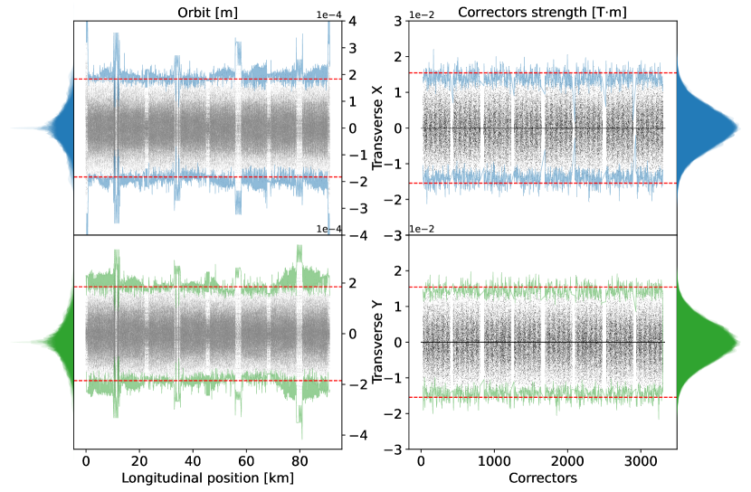
In both the orbit and the corrector strength analyses, we observe that our analytical predictions align well with the simulation data. Specifically, the estimation accurately captures all the data for the vertical plane, while the horizontal plane has a few outliers that exceed the analytical limit. These behaviors can be explained by the combined effect of different errors and the -function, which renders the procedure less effective. Nonetheless, the orbit distribution corresponds to our expectations, with the amplitude in both planes being in the order of magnitude of the MQ offsets (the dominant errors). Moreover, the pattern of the succession of the arcs and insertions is apparent, as we only applied the errors on the arcs, and the residual orbit after correction in the insertions should be almost zero. The RMS values for each successful seed are distributed around the dashed red line representing one analytical RMS estimate. The blue dots correspond to the RMS after turning on the sextupoles and correcting the orbit once, always using a Singular Value Decomposition (SVD) algorithm. Few outlier seeds exist that do not improve with the iteration of the corrector procedure.
Regarding the correctors’ strength distribution (see figure 3), we observe that the strengths are contained in the 3 times mean analytical RMS limit. Therefore, the first specifications for the main magnets’ misalignment of the High Energy Booster arcs cells are set to 150 m, with a maximum corrector strength of about 20 mTm, as far as orbit correction is concerned. These values will be confirmed or potentially reduced following the full emittance tuning performance study.
4 Collective effects and injection parameters
The high energy booster’s smaller pipe radius of 25 mm, compared to the collider’s 35 mm, and almost 100 km circumference, along with the required injection energy and bunch population for the desired emittance at different operating modes (shown in table 1), make collective effects important. Two of these effects being investigated are the resistive wall and intrabeam scattering (IBS).
As for the resistive wall, because of the reduced pipe diameter, the impedance and the wakefield contributions are expected to be higher than the main rings Migliorati et al. (2018); Migliorati, M. et al. (2021) in both longitudinal and transverse plane111these two effects scale as in the longitudianl plane and as in the transverse one..
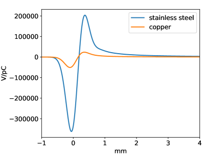
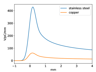
Another important point related to the resistive wall is the possible presence of eddy currents that could be generated by the ramp of the magnetic field during acceleration. In order to avoid them, an initial proposal of a stainless steel vacuum chamber was discussed. This material would have increased the resistive wall contribution by a too large amount. However, due to the low magnetic field in the booster 222according to the CDR Benedikt et al. (2018) from 0.005 T at 20 GeV to a maximum peak of 0.046 T at 182.5 GeV, with a rate of field change below 0.03 T/s., the eddy currents are not expected to be a problem, giving, as consequence, that it is possible to have a stainless steel vacuum chamber with a copper coating of 1 mm, so that, from about 2 KHz on, the skin depth is such that the beam sees only the copper. However, one simple way to fabricate such a vacuum chamber would give, as a final result, a copper pipe with a stainless steel strip about 1 mm wide333Private communication. seen by the beam. This strip would produce an azimuthal asymmetry in the impedance and this contribution, also taking into account the detuning (quadrupolar) terms, has to be studied in detail. In this section, we present only preliminary results for a circular beam pipe made of copper. The longitudinal and transverse wake potentials of a 0.2 mm Gaussian bunch used as a pseudo-Green function for copper and stainless steel are shown in figure 4.
With such contributions, the effects on beam dynamics have been studied with the PyHEADTAIL tracking code Li et al. (2016). As initial conditions for the bunch distribution we have supposed a transverse emittance of mmmrad in the horizontal plane and 1.4 mrad in the vertical plane, with an equilibrium relative energy spread of and a zero current bunch length of about 2.2 mm.
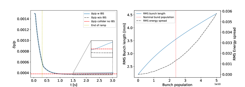
The effect of the longitudinal wakefield is shown in figure 5. We can see that, at the nominal bunch population of we have an effect of the potential well distortion, but also a slight microwave instability which increases the energy spread by a few percent with respect to its nominal value.
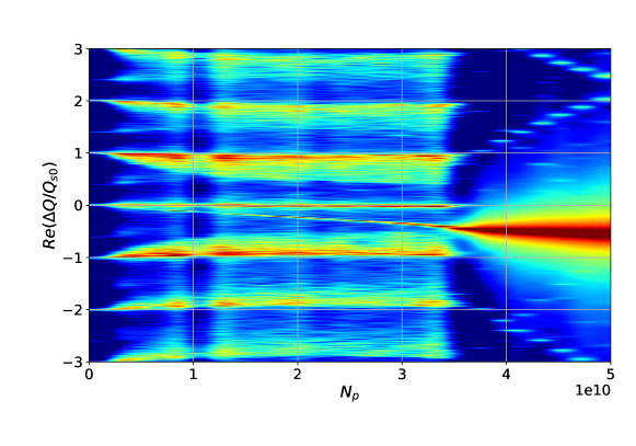
In the transverse plane, the wakefield can produce Transverse Mode Coupling Instability (TMCI), which can be more dangerous than microwave instability because it can cause beam loss. The instability occurs when two coherent oscillations modes couple together. As shown in figure 6 Métral and Migliorati (2020), the threshold is higher than the nominal current, but the safety margin is not so large.
It is important to note that the presented results provide only a rough evaluation of the collective effects on the beam dynamics of the booster. Self-consistent simulations that take into account the intrabeam scattering and wakefields, both influencing the bunch length, must be considered. Additionally, the possible difference in the resistive wall impedance due to the presence of the strip, which produces also an asymmetry with contributions to the detuning (quadrupolar) impedance, must be carefully evaluated. Finally, the machine impedance model has to be built. For the IBS, an updated analytical study made with MadX with respect to the one published in Dalena et al. (2022) is represented in figure 5. It shows an important contribution of the IBS after energy ramp to the energy spread making it higher than the collider threshold. This result is however to be confirmed with tracking simulation taking into account simultaneously the wakefield and the IBS.
5 RF parameters and frequency choice
As the HEB is central in the accelerator complex design, it provides inputs to the different working group studies. One of these inputs is the radiofrequency (RF) total voltage budget, which depends, among other things, on the bunch length needed at extraction for different energy modes and the RF frequency of the accelerating cavities. Recently, the base design of the RF frequency has changed from 400 MHz to 800 MHz, requiring a revision of the total voltage budget. Assuming no energy gain (), one can calculate the resulting RF voltage using the Eq \eqrefeq.Vrf:
| (2) |
In this equation, C represents the booster circumference, is the bunch length, is the total energy, is the slippage factor, is the normalized velocity, is the RF cavities frequency, is the synchrotron energy loss per turn, and is the energy spread.
At injection energy, the momentum acceptance is taken as a criterion for the calculation of the cavities RF voltage budget by solving Eq. \eqrefeq:dp:
| (3) |
with the synchronous tune and the synchronous phase.
As can be seen in table 1, the frequency change from 400 MHz to 800 MHz allows to reduce the total cavities RF budget required at extraction. However, taking the momentum acceptance as a requirement at injection almost doubles it when the RF frequency is doubled.
| Modes | Injection 444 phase advance lattice of the Z and W modes/555 phase advance lattice of the H and modes | Z | W | H | [Units] | |
| Energy | 20 | 45.6 | 80 | 120 | 182.5 | [GeV] |
| 666Bunch length | 4 | 4.38 | 3.55 | 3.34 | 1.94 | [mm] |
| 777Momentum acceptance | 3 | 4.38 | 3.55 | 3.34 | 1.94 | [mm] |
| 888Momentum compaction factor | 14.9 / 7.34 | 14.9 | 7.34 | [] | ||
| 999RF voltage for | 53.6 / 27.6 | 124.6 | 1023.2 | 2185.6 | 14205.4 | [MV] |
| 101010RF voltage for | 104.8 / 52.8 | 83.9 | 623.6 | 2038.3 | 11554.9 | [MV] |
6 Alternative Optics
In the baseline, the arcs are made of FODO cells with a phase advance of / respectively for the modes / and /. The main reason is a larger momentum compaction at injection at the / modes to manage stronger collective effects due to a larger current. However, to enlarge the dynamic aperture, the sextupole scheme is based on a non-interleaved scheme with a phase advance of between two sextupoles of a pair. Maintaining the possibility to have / implies to have a different cabling for the different operation modes. Moreover, the number of sextupoles is roughly doubled.
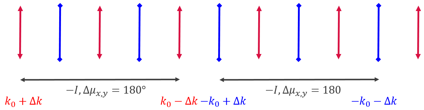
We propose an alternative scheme which enables to tune the momentum compaction by keeping the same non-interleaved scheme for all operation modes. The principle is to create a dispersion and betatron wave at one quadrupole near a sextupole. We assume for instance that the integrated quadrupole strength is modified by ; the quadrupole near the other paired sectupole is modified by (see figure 7). The phase advance between the center of the 2 quadrupoles is in both planes. By this way, the betatron wave is cancelled in the second quadrupole contrary to the dispersion wave (because the frequency of the betatron wave is twice the one of the dispersion wave). The other advantage is also not to change the tune of the cell. If we do the thin lens approximation then to get a relative change of on the momentum compaction, we should have
The advantages of this scheme are to simplify the cabling and distribution of the sextupoles in the arcs; to enable to tune the momentum compaction during the ramp and thus to get a smaller equilibrium emittance for the / modes; to be compatible with any arc pattern if the phase advance between the sextupoles is still . The drawbacks are an additional power supply for the quadrupoles (but that should be less expensive than increasing the number of sextupoles if we have to keep non-interleaved scheme for / cells), a larger equilibrium emittance in comparison with a FODO cell giving the same momentum compaction, a possible reduction of the dynamic aperture and momentum acceptance.
7 Conclusion
This paper reports on the status of several ongoing parallel developments for the FCC-ee High Energy Booster. One of the ongoing studies focuses on particle stability in longitudinal phase space, particularly with regard to the control of synchro-betatron excitations. Other investigations are aimed at evaluating the performance of the current HEB optics design, in particular with respect to stability against lattice elements imperfections, main sextupoles settings, and the interplay of collective effects with a realistic lattice model. By integrating Wakefield and IBS, together with synchrotron radiation, we aim to gain important insights into the injection parameter constraints. These simulations will also allow us to compare the effects of different energy ramping strategies.
All these studies will provide input for alternative optics design and RF parameter choices for the different operating modes, while maintaining compatibility with both pre-injectors and collider requirements. However, it is important to note that these studies are highly dependent on various inputs such as accelerating cavities RF frequency, bunch population, vacuum pipe geometry, material and coating, and collider length, among other parameters. Therefore, they must be conducted in parallel and in dynamic interaction with other ongoing studies such as pre-injectors, collider optics, radio-frequency, or arcs optics patterns to ensure that all the necessary inputs are taken into consideration, and that the most optimal solutions are achieved.
Acknowledgements
This work was supported by the European Union’s Horizon 2020 Research and Innovation programme under grant no. 951754 (FCCIS).
References
- Benedikt et al. (2018) Michael Benedikt, Volker Mertens, Frank Zimmermann, Francesco Cerutti, Thomas Otto, John Poole, Olivier Brunner, Johannes Gutleber, Attilio Milanese, Alain Blondel, et al. Fcc-ee: The lepton collider: Future circular collider conceptual design report volume 2. Eur. Phys. J. Spec. Top., 228(CERN-ACC-2018-0057):261–623, 2018.
- Dalena et al. (2022) B. Dalena, A. Chance, F. Antoniou, O. Etisken, A. Mashal, T. Raubenheimer, M. Zampetakis, and F. Zimmermann. Status of the High Energy Booster of the lepton option of the future circular collider. PoS, ICHEP2022:042, 11 2022. doi:10.22323/1.414.0042.
- Wiedemann (2015) Helmut Wiedemann. Particle accelerator physics. Springer Nature, 2015.
- Dalena et al. (2023) Barbara Dalena, Tatiana Da Silva, Antoine Chance, and Adnan Ghribi. Definition of tolerances and corrector strengths for the orbit control of the high-energy booster ring of the future electro-positron collider. In 14th International Particle Accelerator Conference (IPAC2023), 2023.
- Migliorati et al. (2018) M. Migliorati, E. Belli, and M. Zobov. Impact of the resistive wall impedance on beam dynamics in the future circular collider. Phys. Rev. Accel. Beams, 21:041001, Apr 2018. doi:10.1103/PhysRevAccelBeams.21.041001. URL https://link.aps.org/doi/10.1103/PhysRevAccelBeams.21.041001.
- Migliorati, M. et al. (2021) Migliorati, M., Carideo, E., De Arcangelis, D., Zhang, Y., and Zobov, M. An interplay between beam-beam and beam coupling impedance effects in the future circular e+e- collider. Eur. Phys. J. Plus, 136(11):1190, 2021. doi:10.1140/epjp/s13360-021-02185-2. URL https://doi.org/10.1140/epjp/s13360-021-02185-2.
- Li et al. (2016) Kevin Li, H Bartosik, G Iadarola, A Oeftiger, Andrea Passarelli, A Romano, G Rumolo, M Schenk, and S Hegglin. Code development for collective effects. In ICFA Advanced Beam Dynamics Workshop on High-Intensity and High-Brightness Hadron Beams (HB2016), 2016.
- Métral and Migliorati (2020) E. Métral and M. Migliorati. Longitudinal and transverse mode coupling instability: Vlasov solvers and tracking codes. Phys. Rev. Accel. Beams, 23:071001, Jul 2020. doi:10.1103/PhysRevAccelBeams.23.071001. URL https://link.aps.org/doi/10.1103/PhysRevAccelBeams.23.071001.