Special Theory of Relativity for a Graded Index Fibre
Abstract
The speed of light () in a vacuum is independent on a choice of frames to describe the propagation, according to the theory of relativity. We consider how light is characterised in a material, where the speed of light is different from that in a vacuum due to the finite dielectric constant. The phase velocity in a material is smaller than , such that the speed of a moving frame can be larger than the phase velocity, such that the frame can move faster than the speed of light in a material. Consequently, an unusual Doppler effect is expected, and the wavelength in the moving frame changes from the red-shift to the blue-shift upon increasing the speed of the frame. The corresponding energy of the light also changes sign from positive to negative, while momentum is always positive, leading to the changes of sings for the phase velocity and the helicity. In a graded index fibre, where the exact solution is available, even more complicated phenomena are expected, due to the finite effective mass of photons. Upon the increase of the energy gap, generated by optical confinements and optical orbital angular momentum, the effective mass of photons increases. If the gap is large enough, momentum starts to change the sign upon increasing the frame velocity, while the energy of photons is always positive. In this case, the phase velocity diverges if momentum is in agreement with the fame velocity. Contrary to the unusual behaviours of the phase velocity, the group velocity is always below . This thought-experiment might be useful to consider the insight for the polarisation sate of light.
I Introduction
Einstein made a legacy for the establishment of the theory of relativity [1, 2], which continues to attract a wide range of researchers and engineers for more than a century. It was told that Einstein considered how light is seen from an observer travelling as fast as the speed of the light [3], leading to the discovery of the law, that the speed of light () is independent on a choice of a frame to describe propagation of light in a vacuum, incurred by Maxwell equations [4, 5]. The universal relationship of space and time through the Lorentz transformation led various non-trivial results, such as Doppler effects of light, time dilation, length contraction, and the energy-momentum relationship of , where is energy, is momentum, is the rest mass of an object [1, 2, 4, 6, 7]. In order to satisfy the causality, it is strictly forbidden to allow motion faster then [1, 2, 4].
Nevertheless, inside a material, a speed of an moving frame can exceed the speed of light due to the larger refractive index () than 1 of a vacuum, as experimentally proved by Cherenkov radiation [8, 9, 10, 11, 12, 13, 14]. A charged particle with the speed exceeding the phase velocity of light in a material produces a coherent shock-wave, similar to the sonic waves made by a supersonic aircraft. Cherenkov radiation is usually observed in water as a bluish conical ray, emitted from a charged elementary particle, which enabled physicists to observe the neutorino oscillations [15]. Here, we would like to revisit the original proposition of Einstein: how the light is seen in a material from an observer, travelling at the speed exceeding the phase velocity of light?
Our motivation is to understand the internal quantum structure of a photon, especially for getting insights for clarifying the correlation between spin and polarisation [16, 17, 18, 19]. One might think that it is firmly well-established that spin of photons describes the polarisation of light [20, 21, 4, 5, 22, 23, 24, 25] such that the correlation is obvious. However, this is highly non-trivial, as implied by Einstein, confessing that he could not understand what is a light quanta at all after 50 years of continuous considerations [3], regardless of the fact that he established a theory for a photoelectric effect as an evidence of the particle nature of a photon.
We have a hypothesis that polarisation of light is a macroscopic manifestation for spin of a photon as a quantum-mechanical feature. We have shown that a wavefunction of a photon is described by a Helmholtz equation [16, 4, 5], which does not necessarily give a plane-wave form and the solution depends on a profile of the refractive index and a symmetry of the system. A ray of photons, emitted from a laser source, is described by a many-body coherent state [26, 27, 28, 29, 30, 31, 16, 17, 18, 19] with fixed phases, which describe an state for the spin state of macroscopically condensed photons. By calculating the quantum-mechanical average of spin operators, we have shown that the expectation values of spin of photons are actually Stokes parameters in Poincaré sphere [32, 33, 16]. The magnitude of spin becomes , where it the Stokes parameter for the magnitude of polarisation, is the Dirac constant, and is the number of photons in a system, for a coherent ray of photons, which implies that the effective Planck constant becomes a macroscopic value, leading to a macroscopic realisation of a quantum state as polarisation [16]. The photonic orbital angular momentum is also a well-defined quantum-mechanical observable [34, 17, 18], and we have shown that we can split spin and orbital angular momentum from the total optical angular momentum [34, 35, 36, 37, 5, 4, 26, 38, 35, 36, 37, 39, 40, 36, 18] in a GRaded-INdex (GRIN) fibre [41], where the exact solution is available based on a Laguerre-Gauss mode [18]. Spin of a photon is derived by two-dimensional () space-time Dirac equation from the principle of a rotational symmetry for a quantum-mechanical state of a photon [19]. Based on these considerations [16, 17, 18, 19], we believe that the coherent spin state of photons from a laser source is characterised by a broken symmetry state due to the Bose-Einstein condensation of photons, enabled by pumping above the lasing threshold [19]. Consequently, the macroscopically coherent ray of photons from a laser source is described by a single wavefunction such as a Jones vector [5], a chiral Bloch state [20, 21], and a diagonal state [16]. Thus, a simple quantum-mechanical calculation of a spin state is applicable to a coherent photonic ray using a single particle wavefunction, and its manipulation is also straightforward by employing a phase-shifter and a rotator to change the phases of the wavefunction [16].
The aim of this paper is to understand the photonic state in a material seen from an observer travelling at the speed comparable or even larger than the speed of light. In a photonic crystal [42] or an optical fibre [5], the dispersion relationship of a photon is precisely engineered to adjust the speed of light and other photonic properties. We consider a uniform material and a GRIN fibre as examples, because we can treat the dispersion, exactly in an analytic way.
II Principle
II.1 Lorentz transformation
We are not challenging against the established Lorentz transformation at all [1, 2, 4, 43]. The energy scale, we are considering is of the order of 1eV such as for fibre optics, such that the space-time relationship of the vacuum must be robust in the presence of a material. We assume the rest frame of , where fibre optic materials are located, and consider how the light will be observed by the moving from of at the speed of along the positive direction. The Lorentz transformation, , whose determinant is unity, , is defined by
| (5) | |||||
| (10) | |||||
| (13) |
where , and parameters and are determined by the principle of relativity, guaranteeing that the speed of light in a vacuum is independent on the measurement frame. In order to impose the principle, we define the d’Alembertian operators as
| (14) |
By inserting the identity
| (24) |
into d’Alembertian, we obtain
| (26) |
where at . Then, we obtain and , and becomes a standard form [1, 2, 4, 43] of
| (29) | |||||
| (32) |
where and the normalised velocity of the moving frame is given by . By using the Lorentz transformation, the d’Alembertian is always invariant in a vacuum, such that the velocity of light is constant and independent on the choice of the frame. We can also consider the inverse Lorentz transformation as
| (37) | |||||
| (42) |
which is equivalent to exchange
| (43) | |||||
| (44) | |||||
| (45) |
in the original Lorentz transformation, reflecting the principle of relativity. The Lorentz transformation is valid in our argument.
II.2 Schödinger equation for a photon
In a material, the dispersion relationship for a photon is highly non-trivial. In order to provide a specific example, we chose a GRIN fibre, where the exact solution is available [41, 5, 16, 17, 18, 19]. The refractive index of a GRIN fibre () is given by , where is the refractive index of the core, is the graded index parameter, and is the radius in a cylindrical coordinate of . The radial and angular dependences of the wavefunction for a photon in a GRIN fibre can be decoupled by using the Laguerre-Gauss mode [34, 5, 16, 17, 18, 19], which is equivalent to integrating over these degrees of freedom in a Feynman path integral formalism [29, 30, 31, 16, 17, 18, 19]. After eliminating , we confirm the dispersion relationship with the opening up of the energy gap
| (46) |
where the overall shift of the energy is , is the radial quantum number, is the magnetic orbital angular momentum along the principal axis of , and is the effective mass of the photon in a GRIN fibre [29, 30, 31, 16, 17, 18, 19]. Please note the similarity of the original Einstein theory of relativity to assign the rest mas of to its energy as [1, 2]. The emergence of the effective mass is attributed to the broken symmetry of photons due to lasing [19]. It is interesting to note that the obtained dispersion relationship is quite similar to the Bardeen-Cooper-Schrieffer (BCS) theory of superconductivity [44, 45, 46, 47, 48, 49, 50]. The remaining degree of freedom is the propagation of light along in a GRIN fibre, which is described by the Schrödinger-like equation
| (47) |
where is the wavefunction of a photon, is the Dirac constant, and we have re-defined the d’Alembertian
| (48) |
to account for the reduced speed of light in a material. The wavefunction along becomes a simple plane wave,
| (49) |
while the dispersion for the guided mode [19] becomes
| (50) |
In deriving this energy-momentum dispersion relationship, we assumed de-Broglie relationship
| (51) | |||||
| (52) |
where is the angular frequency and is the wavenumber for the photon with the wavelength of .
II.3 Lorentz transformation in a uniform material
First, we examine the weak coupling limit of . In this case, the energy gap vanishes, , and the wave equation becomes
| (53) |
Thus, a photon is massless with the reduced velocity of in a uniform material of the refractive index of . The dispersion relationship is linear,
| (54) |
and the phase velocity is given by .
By applying the Lorentz transformation to the wave equation, we obtain the corresponding wave equation in the moving frame as
| (55) | |||||
Inserting the trial function of the form,
| (56) |
we obtain the dispersion relationship in the moving frame,
| (57) |
The phase velocity in the frame is given by
| (58) |
We can obtain the same dispersion relationship, by simply inserting the Lorentz transformation into the original wavefunction as
| (59) | |||||
| (60) |
which leads
| (61) | |||||
| (62) |
II.3.1 Vacuum limit
We check the obtained dispersion in the know limit of the vacuum, such that we take the limit of . In this case, we reproduce a standard theory of relativity [1, 2, 4]. We obtain
| (63) | |||||
| (64) |
from which we obtain the Doppler effect for the light by setting , we obtain
| (65) |
We expect the red-shift for , since the light source is relatively going away such that the wavelength is elongated for the observer moving away from the light source. On the other hand, the blue-shift is expected for , since the light source is approaching to the observer. We can also confirm the principle of relativity by exchanging and at the same time, the relationship between and are not altered.
II.3.2 Uniform material
We assumed the material is at rest in the frame of and the moving frame of is not equivalent to the original frame any more. In this case, the wavenumber of is always positive, while the angular frequency of can change its sign upon increasing the frame velocity of . Consequently, the phase velocity of can also change sign, such that the light is seen to be propagating to the backward, if the frame is moving faster than the speed of light in a material, which is indeed possible as is know for the case of the Cherenkov radiation [8, 9, 10, 11, 12, 13, 14]. We can see the consequence of the Lorentz transformation by examining several typical limits of the obtained phase velocity of (Table 1). The details of the calculated parameters are discussed in the next section (Fig. 1).
| Limit | Phase velocity | Comment |
|---|---|---|
| Vacuum limit | ||
| Rest limit | ||
| Frame moving slower than light | ||
| Stopping light | ||
| Frame moving faster than light | ||
| Maximum velocity |
II.4 Lorentz transformation in a GRIN fibre
In a GRIN fibre, the dispersion relationship is different from a uniform material, due to the band-gap opening, as we have outlined above [34, 5, 16, 17, 18, 19]. We can obtain the corresponding dispersion relationship observed in a moving frame. The main assumption is the plane wave form of the solution along and and the validity of the space-time relationship by the Lorentz transformation. Consequently, we obtain
| (66) |
which gives
| (67) | |||||
| (68) |
The relationship is simply summarised as the Lorentz transformation of
| (73) |
This is equivalent to impose the de-Bloglie relationship in the moving frame as
| (74) | |||||
| (75) |
which gives the Lorentz transformation of the energy-momentum relationship as
| (80) |
which must be valid for an arbitrary dispersion beyond the dispersion for a GRIN fibre. The relative symmetry against a frame exchange does not exist any more with a material, because the rest frame with a material is different from the moving frame. Consequently, we obtain non-trivial Doppler effects, as shown in the next section.
III Results
III.1 Doppler effects in a uniform material
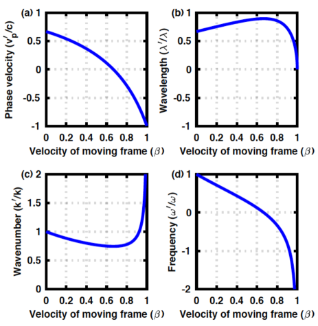
First, we show numerical results in a uniform material (Fig. 1). We assumed and , and the wavelength of m, considering typical parameters of a glass fibre [5]. Upon increasing the frame velocity of , the phase velocity of decreases and changes sign at and approaches in the maximum limit of (Fig. 1 (a)).
We expect the red-shift for , since the observer in the moving frame is going away from the light source in the rest frame, such that the wavelength is elongated, while the blue-shift is expected for (Fig. 1 (b)). By assuming , we obtain the wavelength in the moving frame
| (81) |
We confirm the appropriate limit of for , while the limit of for might be non-trivial. We expect the peak of the wavelength at
| (82) |
which indeed gives . We are considering the continuous wave, emitted from the light source in the rest frame, rather than a pulsed operation. If the frame is moving above the speed of light in the rest frame, the frame is approaching to the light, which was emitted earlier, such that the wavelength of the light is observed shorter than that in the rest frame. The wavenumber is always positive (Fig. 1 (c)), since the refractive index of a material is always larger than unity () and the frame cannot move larger than ().
On the other hand, the angular frequency of changes sign at , such that the polarisation state starts to rotate in the opposite way, as if the time is going backward (Fig. 1 (d)). This could be considered by defining a chiral operator defined by
| (83) | |||||
| (84) |
In the moving frame, we consider
| (85) |
which changes sign at . Therefore, the helicity is reversed upon increasing .
III.2 Doppler effects in a GRIN fibre
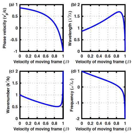
Next, we consider the Doppler effects in a GRIN fibre. We assume the same core of for the wavelength of m, while the energy gap of is chosen as a parameter.
The numerical results at are shown in Fig. 2. The qualitative features are not changed for the case of a uniform material (Fig. 1). The critical frame velocity, required to change the sing of the phase velocity, is increased due to the opening of the band gap (Fig. 2 (a)). We expect more significant red- and blue-shifts upon increasing (Fig. 2 (b)), but is always positive and changes sign, as before.
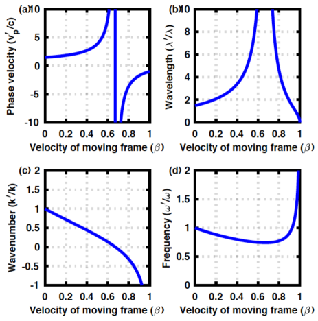
On the other hand, for the larger at , Doppler effects are even more anomalous. In this case, changes sign, while is always positive. This is attributed to the larger contributions to the total energy of from orbital degrees of freedoms through the radial oscillations and/or photonic orbital angular momentum, characterised by and [34, 5, 16, 17, 18, 19]. As a result, the contribution of the kinetic energy for the propagation along is limited, such that the frame is easier to go beyond the speed of the light, which allows to change the sign (Fig. 3 (a)). For , we have assumed to extract the wavelength of in the moving frame (Fig. 3 (b)).
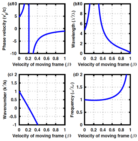
The maximum energy gap is , where we cannot expect any propagation along , and the optical mode is trapped solely in the direction perpendicular to the fibre. Close to this limit, we assumed and the results are shown in Fig. 4. changes its sign even at the smaller , as expected for the limited kinetic energy.
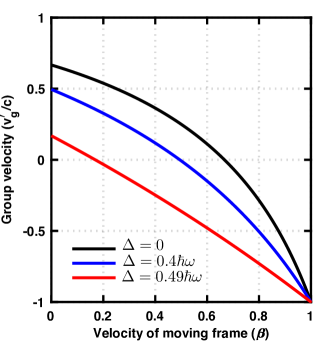
Regardless of the anomalous phase velocity of , exceeding to (Figs. 3(a) and 4(a)), this does not mean the violation of the relativity at all, because the optical communication is determined by the group velocity, defined by
| (86) | |||||
| (87) |
As shown in Fig. 5, is always smaller than , such that the optical communication beyond is strictly prohibited. The critical velocity of to change the sign of does not necessarily coincide with the velocity of to change the sign of .
III.3 Impacts on polarisation states
Finally, we discuss the implications of our considerations for understanding of the polarisation states of photons. Before discussing the application of the general theory of relativity to the GRIN fibre, we need to clarify the definition of the polarisation states, because the direction of the apparent propagation changes in the frame moving faster than the phase velocity of the light in the rest frame.
III.3.1 Lights propagating in opposite directions
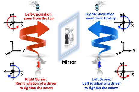
We clarify the definition of the polarisation states [16], in particular, the direction of the rotation (Fig. 6). There are a lot of different choices of the conventions [4, 5, 22, 23, 16], and any notation is acceptable as far as it is used consistently. We prefer to define the polarisation state, seen from the detector side, because it is straightforward to describe the motion of the phase front in a standard right-handed coordinate (Fig. 6). We assume that the plane wave of the form is propagating along the direction (Fig. 7(a)), and the principal axis () of the polarisation state is locked along the direction of the propagation [16]. In our definition, the left-circular-polarised state () is located at in the normalised Poincaré sphere, while the right-circular-polarised state () is located at (Fig. 7(e)). These states are mirror images of each other, and in fact, a mirror can change the circular polarised states to the opposite ones [5, 16, 22, 23].
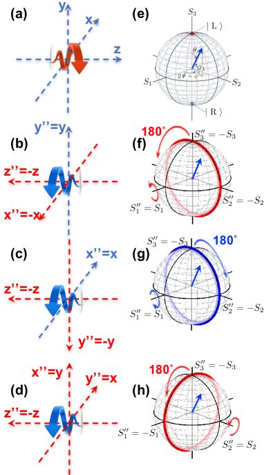
We consider how we should describe the polarisation states for the light propagating to the opposite direction (Fig. 7), since we encountered the situation that the moving frame can go faster than the speed of the light in a material, for which the light is seen to go backward, in the previous sections. The situation is similar to consider the reflection from the mirror (Fig. 6), since a mirror changes the direction of propagation as well as the polarisation state. For example, we consider the left-circular-polarised light propagating along direction (Fig. 7 (a)), which is characterised by (Fig. 7 (e). We consider this light is reflected backwards without changing the rotation of the phase front (Fig. 7 (b)), while the direction of the propagation is opposite (). If we are keeping observing the phase front, seen from the direction, the circulation is unaffected as the anti-clock-wise rotation. However, we defined that the polarisation state must be identified from the detector side, which is direction (Fig. 7 (b)). Thus, we define a new frame of , assuming to clarify the polarisation state. The reflected light propagating along is now circulating to the clock-wise direction, seen from the direction, thus it should be described by the right-circular-polarised state with (Fig. 7 (f)). Considering the opposite direction of the propagation, it is natural to assign , if we would like to keep using the original axes for Stokes parameters. Here, we still have a freedom to choose the relative phase of axes (Figs. 7 (b)-(d)) to the original one (Fig. 7 (a)). These choices correspond to how to rotate the original Poincaré sphere at the angle of (Figs. 7 (f)-(h)). The rotation of the polarisation state is described by a rotation operator in Lie algebra [51, 52, 20, 21, 4, 5, 22, 23]. If we use the chiral LR-basis, the rotation operator becomes
| (88) | |||||
| (89) |
where is the unit vector for the rotational axis, are Pauli matrices, and is the angle of the rotation. For example, the rotation along for (Fig. 7 (f)) is given by
| (90) |
while the opposite rotation for Fig. 7 (g) is described by
| (91) |
Similarly, the rotation along for (Fig. 7 (h)) is given by
| (92) |
These rotations are connected each other. For example, the coordinate of Fig. 7(d) is realised by rotating Fig. 7 (b) for , which correspond to the rotation along [17],
| (93) |
In fact, we confirm
| (94) |
Similarly, we can rotate the coordinate of Fig. 7 (c) for , which correspond to the rotation along , and we confirm
| (95) |
The arbitrary degree of freedom to chose the axes is actually not restricted to the reflected beam. For example, if we have a linear diagonally polarised state, which is described by , by changing the definition of the -axis by rotating , it can also be regarded as the horizontally polarised state of . Therefore, the difference of the apparent polarisation states between and simply depends on the choice of the frame.
Among various arbitrary choices of the frame for the reflected light (Figs. 7 (b)-(d)), however, one of the most sensible choice would be that of Fig. 7 (d). In this case, the impact of the frame exchange is similar to the unitary transformation by the mirror operation of
| (98) |
whose impact on the spin operators would be
where ∗ is the complex conjugate and † is the Hermite conjugate, which involves the transpose of the matrix in addition to the complex conjugate. In this convention, we understand that the polarisation state for the light propagating in the opposite direction of is described by the complex conjugate representation of the Lie algebra [53, 54] in the original frame as
| (111) |
which is consistent with Fig. 7 (h). The complex conjugate representation also satisfies the same commutation and anti-commutation relationships with those of the original Pauli matrices [53, 54], such that we confirmed the duality of representations. Therefore, if we would like to keep working in the original frame of for the light propagating in the opposite direction, we should use the complex conjugate of the spin operators, defined by
| (112) | |||||
| (113) | |||||
| (114) |
where the spinor representation of the creation and annihilation field operators are
| (115) | |||||
| (118) |
using the creation and annihilation operators of and for photons in the polarisation states of left- () and right- () polarised states, respectively.
III.3.2 Polarisation states observed from a moving frame
Now, we are ready to discuss the polarisation state of light, seen from an observer in the frame of moving as fast as the phase velocity of light in the rest frame of , where the fibre optic material is placed. We consider that the frame of is at rest against the frame of .
First, we consider the weak coupling limit of , which corresponds to a uniform material with the refractive index of . The wavenumber of is always positive, such that the momentum of is always pointing towards the positive direction (Fig. 1(c)). On the other hand, changes its sign as is increased (Fig. 1(d)), leading to the change of the sign in for . Suppose that the light at the left-circularly-polarised state () in the original frame is propagating along . As far as the velocity of the frame is small, , the polarisation state, seen from the frame of is not affected, and we obtain and the light is seen to be rotating in the anti-clock-wise direction, seen from . At , the light is seen to be propagating along , such that the polarisation state should be examined from the frame of , where the light is propagating along the positive direction. The rotation of the phase front, seen from direction, is anti-clock-wise due to the negative and the observation from the opposite side from the original frame of . Thus, we conclude , such that the light is still in the left-circular-polarised state. If we consider the complex conjugate relationship between the frames of and , we obtain , such that the apparent spin expectation value of depends on the relative velocity of the frame, as is similar to frame-dependent momentum () and energy () governed by Lorentz transformation. For the linearly polarised states, we do not have to be careful too much on the direction of the oscillations, changed by the sign of , because the rotation of the phase front is not involved. However, the description of the polarisation state depends on the choice of the frame (Fig. 7 (b)-(d)). Assume that we have chosen our preferential frame of Fig. 7 (d) and we consider the linear-horizontally-polarised state of in the original frame of . For , the polarisation state is not affected, such that we expect , while for , we should use the frame of and the direction of oscillation is considered to be . Therefore, we conclude that the polarisation state becomes , which is vertically polarised state. This is merely coming from the choice of the frame, and if we convert it to the frame of , we obtain , which has not been changed upon increasing . We can consider a more complicated polarisation state, but the argument is straightforward.
Next, we consider the polarisation state in a GRIN fibre. As far as the confinement is weak (fig. 2), the qualitative situation is the same as that for a uniform material, discussed above. Therefore, we focus on the strong coupling limit (Figs. 3 and 4), where changes the sign upon increasing (Figs. 3(c) and 4(c)), while is always positive (Figs. 3(d) and 4(d)). In these cases, the direction of the rotation of the polarisation state will not be changed by , while we must judge the polarisation state seen from the direction of the propagation, which is changed. Suppose we are considering the light of left-circularly-polarised state propagating direction in the frame of , such that the original state is . In the frame of , the direction of the propagation could be changed for , and the polarisation state is examined from . In this case, the phase front is seen to be rotating along the clock-wise-direction, because it is observed from the opposite side of the original frame of and is always positive. Thus, we conclude and the light is in the right-circularly-polarised state. This corresponds to , and such that the magnetic spin angular momentum along the principal axis seems to be preserved in spite of the large , if the mode confinement is very strong. The argument for the linearly polarised state is not altered by the confinement, because it is mainly affected by the choice of the frames and the sign of cannot change the direction of the polarisation, although it affects to the direction of the propagation.
IV Conclusion
We considered how the light will be seen in a material, if an observer is moving as fast as the phase velocity of the light. As a specific example, we considered a graded index fibre, where the photon dispersion is massive due to the confinement of the orbital, which is quantised both for radial and angular directions. We see that the phase velocity could change the sign, which means that the moving frame can go faster than the speed of light in a material, as evidenced by the Cherenkov radiation [8, 9, 10, 11, 12, 13]. We found a crossover from a red-shift to a blue-shift of light as the observer increases the speed beyond the phase velocity. If the optical confinement in the fibre is strong, we found that anomalous Doppler effects, with the divergent phase velocity, exceeding the speed of light in a vacuum, while the group velocity is always less than , confirming the causality and the validity of relativity. We have also discussed how the polarisation state is considered in the moving frame, for which the light could be observed to be propagating to the opposite direction from the original frame. We established that the spin operators for the light propagating in the opposite direction are described by the complex conjugate of the original spin operators, which shows the duality of the representations in Lie algebra [53, 54]. We are not proposing to confirm this thought-experiment in reality, even if it might be possible. Instead, we think our consideration might be useful as a platform for challenging towards the long-term mystery of what is a photon, imposed by Einstein [1, 2, 3].
Acknowledgements
This work is supported by JSPS KAKENHI Grant Number JP 18K19958. The author would like to express sincere thanks to Prof I. Tomita for continuous discussions and encouragements.
References
- Einstein [1905a] A. Einstein, Concerning an heuristic point of view toward the emission and transformation of light, Ann. Phys. 17, 132 (1905a).
- Einstein [1905b] A. Einstein, On the electrodynamics of moving bodies, Ann. Phys. 17, 891 (1905b).
- Lehner [2014] M. Lehner, The Cambridge Companion to Einstein (Cambridge Companions to Philosophy) (Cambridge University Press, 2014).
- Jackson [1999] J. D. Jackson, Classical Electrodynamics (John Wiley & Sons, 1999).
- Yariv and Yeh [1997] Y. Yariv and P. Yeh, Photonics: optical electronics in modern communications (Oxford University Press, 1997).
- Garetz [1982] B. A. Garetz, Angular doppler effect, J. Opt. Soc. Am. 71, 609 (1982).
- Nienhuis [1996] G. Nienhuis, Doppler effect induced by rotating lenses, Opt. Comm. 132, 8 (1996).
- Cherenkov [1934] P. A. Cherenkov, Visible light from clear liquids under the action of gamma radiation, C. R. (Dokl.) Acad. Sci. URSS 2, 451 (1934).
- Frank and Tamm [1937] I. M. Frank and I. E. Tamm, Coherent visible radiation of fast electrons passing through matter, C. R. (Dokl.) Acad. Sci. URSS 14, 109 (1937).
- Cherenkov [1937a] P. A. Cherenkov, Visible light of pure liquids under the action of hard beta-radiation, C. R. (Dokl.) Acad. Sci. URSS 14, 101 (1937a).
- Cherenkov [1937b] P. A. Cherenkov, Angular dependence of the intensity of light emission, produced by gamma-radiation in pure liquids, C. R. (Dokl.) Acad. Sci. URSS 14, 105 (1937b).
- Cherenkov [1937c] P. A. Cherenkov, Visible radiation produced by electrons moving in a medium with velocities exceeding that of light, Phys. Rev. 52, 378 (1937c).
- Cherenkov [1986] P. A. Cherenkov, At the threshold of discovery, Nucl. Instrum. Methods Phys. Res. A 248, 1 (1986).
- Baryshevsky and Gurnevich [2017] V. G. Baryshevsky and E. A. Gurnevich, Cherenkov and parametric (quasi-Chrenkov) radiation produced by a relativistic chraged particle moving through a crystal built from metallic wires, Nucl. Instrum. Methods Phys. Res. B 402, 30 (2017).
- Fukuda and et. al. [1998] Y. Fukuda and et. al., Evidence for oscillation of atmospheric neutorinos, Phys. Rev. Lett. 81, 1562 (1998).
- Saito and Tomita [sheda] S. Saito and I. Tomita, Spin of photons: Nature of polarisation, (unpublisheda).
- Saito and Tomita [shedb] S. Saito and I. Tomita, Quantum commutation relationship for photonic orbital angular momentum, (unpublishedb).
- Saito and Tomita [shedc] S. Saito and I. Tomita, Spin and orbital angular momentum of coherent photons in a waveguide, (unpublishedc).
- Saito and Tomita [shedd] S. Saito and I. Tomita, Dirac equation for photons: Origin of polarisation, (unpublishedd).
- Baym [1969] G. Baym, Lectures on Quantum Mechanics (Westview Press, 1969).
- Sakurai and Napolitano [2014] J. J. Sakurai and J. J. Napolitano, Modern Quantum Mechanics (Pearson, 2014).
- Goldstein [2011] D. H. Goldstein, Polarized Light (CRC Press, 2011).
- Gil and Ossikovski [2016] J. J. Gil and R. Ossikovski, Polarized Light and the Mueller Matrix Approach (CRC Press, 2016).
- Pedrotti et al. [2007] F. L. Pedrotti, L. M. Pedrotti, and L. S. Pedrotti, Introduction to Optics (Pearson Education, 2007).
- Hecht [2017] E. Hecht, Optics (Pearson Education, 2017).
- Grynberg et al. [2010] G. Grynberg, A. Aspect, and C. Fabre, Introduction to Quantum Optics: From the Semi-classical Approach to Quantized Light (Cambridge University Press, 2010).
- Fox [2006] M. Fox, Quantum Optics: An Introduction (Oxford University Press, 2006).
- Parker [2005] M. A. Parker, Physics of Optoelectronics (Tylor & Francis, 2005).
- Nagaosa [1999] N. Nagaosa, Quantum Field Theory in Condensed Matter Physics (Springer, 1999).
- Wen [2004] X. G. Wen, Quantum Field Theory of Many-Body Systems (Oxford University Press, 2004).
- Altland and Simons [2010] A. Altland and B. Simons, Condensed Matter Field Theory (Cambridge University Press, 2010).
- Stokes [1851] G. G. Stokes, On the composition and resolution of streams of polarized light from different sources, Trans. Cambridge Phil. Soc. 9, 399 (1851).
- Poincar [1892] J. H. Poincar, Thorie mathmatique de la lumire (G. Carr, 1892).
- Allen et al. [1992] L. Allen, M. W. Beijersbergen, R. J. C. Spreeuw, and J. P. Woerdman, Orbital angular momentum of light and the transformation of Laguerre-Gaussian laser modes, Phys. Rev. A 45, 8185 (1992).
- v. Enk and Nienhuis [1994] S. J. v. Enk and G. Nienhuis, Commutation rules and eigenvalues of spin and orbital angular momentum of radiation fields, J. Mod. Opt. 41, 963 (1994).
- Leader and Lorc [2014] E. Leader and C. Lorc, The angular momentum controversy: What’s it all about and does it matter?, Phys. Rep. 541, 163 (2014).
- Barnett et al. [2016] S. M. Barnett, L. Allen, R. P. Cameron, C. R. Gilson, M. J. Padgett, F. C. Speirits, and A. M. Yao, On the natures of the spin and orbital parts of optical angualr momentum, J. Opt. 18, 064004 (2016).
- Bliokh et al. [2015] K. Y. Bliokh, F. J. Rodrguez-Fortuo, F. Nori, and A. V. Zayats, Spin-orbit interactions of light, Nat. Photon. 9, 796 (2015).
- Chen et al. [2008] X. S. Chen, X. F. L, W. M. Sun, F. Wang, and T. Goldman, Spin and orbital angular momentum in gauge theories: Nucleon spin structure and multipole radiation revisited, Phys. Rev. Lett. 100, 232002 (2008).
- Ji [2010] X. Ji, Comment on ”Spin and orbital angular momentum in gauge theories: Nucleon spin structure and multipole radiation revisited”, Phys. Rev. Lett. 104, 039101 (2010).
- Kawakami and Nishizawa [1968] S. Kawakami and J. Nishizawa, An optical waveguide with the optimum distribution of the refractive index with reference to waveform distortion, IEEE Trans. Microw. Theory Techn. 16, 814 (1968).
- Joannopoulos et al. [2008] J. D. Joannopoulos, S. G. Johnson, J. N. Winn, and R. D. Meade, Photonic Crystals: Molding the Flow og Light (Princeton Univ. Press, 2008).
- Weinberg [2005] S. Weinberg, The Quantum Theory of Fields: Foundations volume 1 (Cambridge University Press, 2005).
- Bardeen et al. [1957] J. Bardeen, L. N. Cooper, and J. R. Schrieffer, Theory of superconductivity, Phys. Rev. 108, 1175 (1957).
- Anderson [1958] P. W. Anderson, Random-phase approximation in the theory of superconductivity, Phys. Rev. 112, 1900 (1958).
- Bogoljubov [1958] N. N. Bogoljubov, On a new method in the theory of superconductivity, IL Nuovo Cimento 7, 794 (1958).
- Nambu [1960] Y. Nambu, Quasi-particles and gauge invariance in the theory of superconductivity, Phys. Rev. 117, 10.1103/PhysRev.117.648 (1960).
- Schrieffer [1971] J. R. Schrieffer, Theory of Superconductivity (Westview Press, 1971).
- Goldstone et al. [1962] J. Goldstone, A. Salam, and S. Weinberg, Broken symmetries, Phy. Rev. 127, 965 (1962).
- Higgs [1962] P. W. Higgs, Broken symmetries, massless particles and gauge fields, Phys. Lett 12, 132 (1962).
- Jones [1941] R. C. Jones, A new calculus for the treatment of optical systems i. description and discussion of the calculus, J. Opt. Soc. Am. 31, 488 (1941).
- Payne [1952] W. T. Payne, Elementary spinor theory, Am. J. Phys. 20, 253 (1952).
- Georgi [1999] H. Georgi, Lie Algebras in Particle Physics: from Isospin to Unified Theories (Frontiers in Physics) (Westview Press, 1999).
- Pfeifer [2003] W. Pfeifer, The Lie Algebras An Introduction (Springer Basel AG, 2003).