Towards robust PICOSEC Micromegas precise timing detectors
Abstract
The PICOSEC Micromegas (MM) detector is a precise timing gaseous detector consisting of a Cherenkov radiator combined with a photocathode and a MM amplifying structure. A 100-channel non-resistive PICOSEC MM prototype with 10×10 cm2 active area equipped with a Cesium Iodide (CsI) photocathode demonstrated a time resolution below = 18 ps. The objective of this work is to improve the PICOSEC MM detector robustness aspects, i.e. integration of resistive MM and carbon-based photocathodes, while maintaining good time resolution. The PICOSEC MM prototypes have been tested in laboratory conditions and successfully characterised with 150 GeV/c muon beams at the CERN SPS H4 beam line. The excellent timing performance below = 20 ps for an individual pad obtained with the 10×10 cm2 area resistive PICOSEC MM of 20 M/ showed no significant time resolution degradation as a result of adding a resistive layer. A single-pad prototype equipped with a 12 nm thick Boron Carbide (B4C) photocathode presented a time resolution below = 35 ps, opening up new possibilities for detectors with robust photocathodes. The results made the concept more suitable for the experiments in need of robust detectors with good time resolution.
1 Introduction
The development of technologies for precise timing detectors has been driven by the demanding environments expected in future High Energy Physics experiments. The requirements of a time resolution of tens of picoseconds, stable long-term operation and a large area coverage must be met to make the device suitable. Within the PICOSEC Micromegas (MM) collaboration, a gaseous detector designed to achieve precise timing response is being developed [1, 2, 3]. First proof-of-concept single-pad prototypes demonstrated a time resolution below = 25 ps [1]. A recent multipad PICOSEC MM indicated how precise time resolution can be achieved with a non-resistive 100-channel gaseous detector with 10×10 cm2 active area equipped with a CsI photocathode, showing a time resolution below = 18 ps [3]. Although the first tests of alternative, more robust approaches have been performed in the past (i.e. timing measurements of single-pad prototypes with resistive MM and Diamond-Like-Carbon (DLC) photocathodes [4]), new developments including the integration of resistive MM in 100-channel modules and robust Boron Carbide (B4C) photocathodes have not been studied up to now. The objective of this work is to improve the PICOSEC MM detectors robustness aspects while maintaining a good time resolution.
2 Detection concept
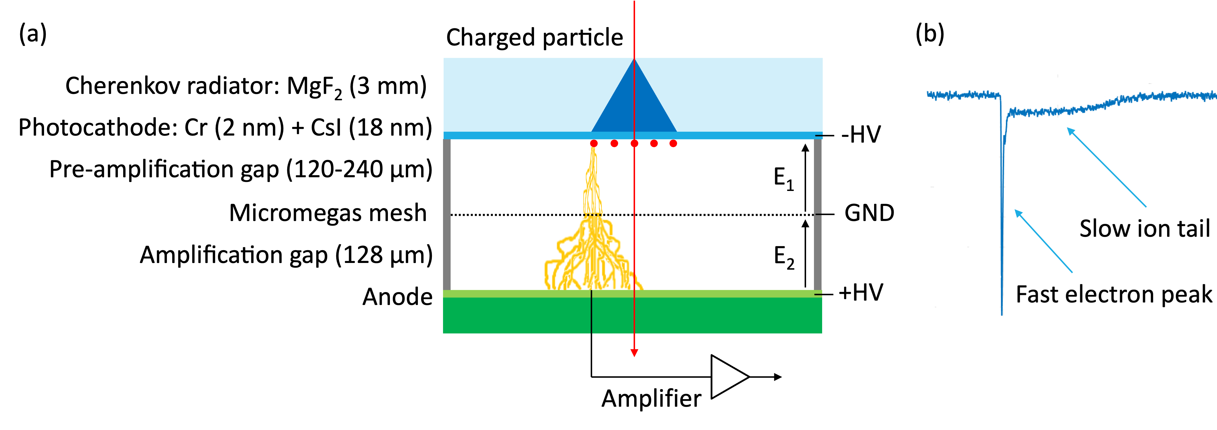
The PICOSEC MM detection concept [1] is illustrated in Fig. 1 (a). A charged particle passing through a Cherenkov radiator, creates a cone of ultraviolet (UV) photons which are converted into primary electrons on a photocathode coated directly on the radiator. Due to a high electric filed, the extracted electrons successively ionise the gas molecules, causing the multiplication of the electrons, first in the preamplification gap, and then, after passing through the MM mesh, in the amplification gap. A gas mixture of 80 Neon, 10 CF4 and 10 Ethane at ambient pressure is used to fill both regions. The amplified electrons induce a signal on the anode which is passed through an amplifier and read out by a digitizer. A typical PICOSEC MM waveform consists of a fast electron peak and a slow ion tail, as presented in Fig. 1 (b). The rising edge of the electron peak is used to extract the time of arrival of the charged particle.
3 Experimental setup
The PICOSEC MM prototypes have been tested for stable operation in laboratory conditions and successfully characterisied at the CERN SPS H4 beam line with 150 GeV/c muon beams during RD51 test beam campaigns. The main purpose of the muon beam characterisation was to measure the time resolution of the detectors. The experimental setup was based on a beam telescope with triggering, timing and tracking capabilities. Triple-GEMs were used to obtain the precise tracking of the particles, while a micro-channel plate photomultiplier tube (MCP-PMT, Hamamatsu R3809U50) was used as timing reference (time resolution in the inner part of the active area below = 4 ps [5]) and data acquisition trigger. As the new electronics dedicated for multipad device, custom-made RF pulse amplifier cards optimised for PICOSEC [6] and 128-channel SAMPIC Waveform Time to Digital Converter [7] with 8.5 GS/s sampling frequency were used.
4 Resistive Micromegas
Resistive MM are essential to make the PICOSEC concept suitable for physics applications. The advantages of using resistive MM in the PICOSEC detector include the limitation of the destructive effect of discharges, resulting in stable operation under intense particle beams, as well as a possibly better position reconstruction and signal sharing. A possible risk of a resistive MM implementation may be to affect the shape of the signal, in particular the rising edge, by spreading the signal due to the resistive layer, which could result in a loss of the timing information. The objective is to profit from the advantages of the resistive MM while maintaining a good time resolution. To choose an optimal resistivity, two aspects must be considered. Firstly, the resistivity must be low enough to minimise the voltage drop during high-rate beam and improve the position reconstruction using the signal weighted average from neighbouring pads. Secondly, the resistivity needs to be high enough to ensure stable operation and not affect the rising edge of the signal. Simulations of rate capability and signal rising edge dependence were performed to select the resistivity for the new PICOSEC prototype. Informed by the simulations, a 100-channel detector with a 10×10 cm2 area resistive MM with anode surface resistivity of 20 M/ was produced. The production procedure was done in the same way as for a non-resistive multipad [3] with an additional step of adding a resistive layer of DLC that was placed on top of the readout pads with an insulating layer in between.
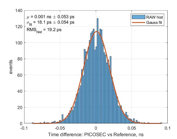
First test beam measurements of the multipad equipped with a resistive MM of 20 M/, a CsI photocathode and RF pulse amplifiers were performed with an oscilloscope to compare the results with a non-resistive prototype [3]. The time resolution of the detector was calculated as the standard deviation of the signal arrival time (SAT) distribution. The measurements of the 10×10 cm2 resistive PICOSEC MM of 20 M/ showed a time resolution below = 20 ps for an individual pad, as can be seen in Fig. 2. The results confirm that adding a resistive layer does not affect the time resolution of the detector to a significant extent.
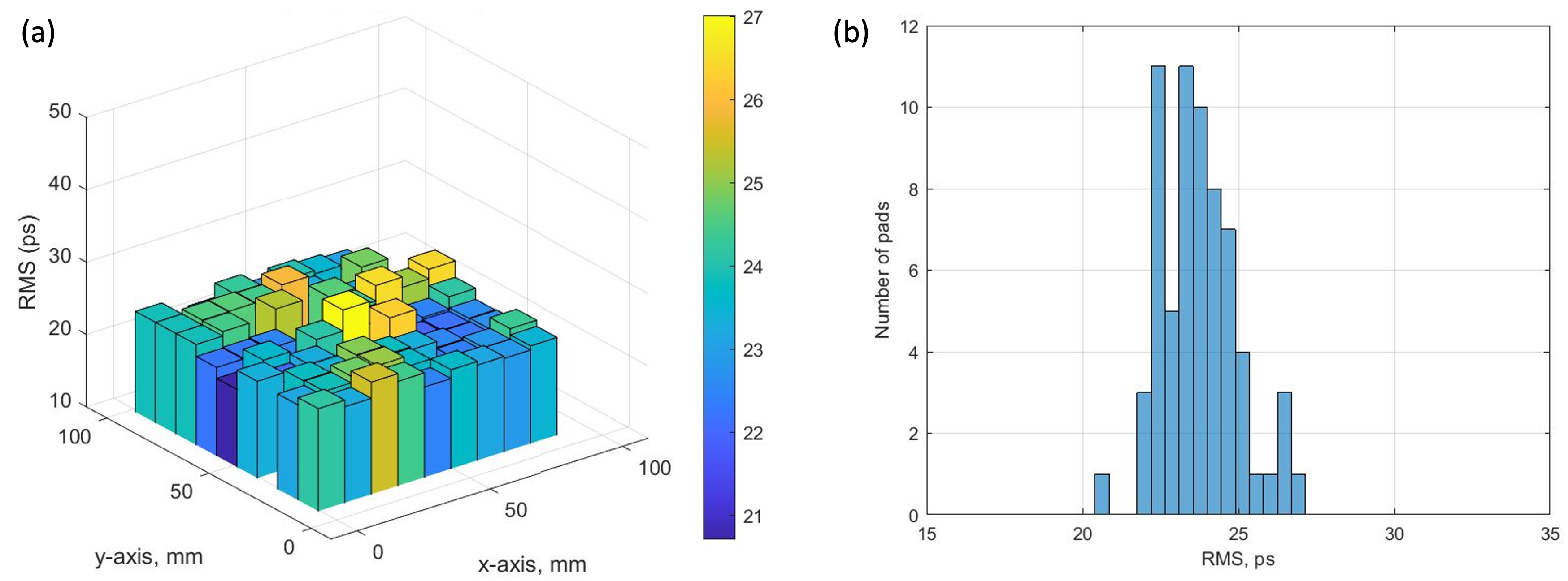
To characterise the full detector, the SAMPIC digitiser was used [7]. The objective was to measure the timing precision. The measurements of the time resolution across the 10×10 cm2 area resistive PICOSEC MM of 20 M/ are presented in Fig. 3. First results obtained with the new digitizer showed uniform timing response within the pads and a narrow distribution of the time resolution across the channels with the mean value of 23 ps, proving SAMPIC to be a suitable tool to study the response of 100-channel PICOSEC detector.
5 Robust photocathodes
The base UV-to-electron converter for the PICOSEC MM detector is a semi-transparent CsI photocathode. The high quantum efficiency of CsI leads to the production of around 10 photoelectrons per minimum ionizing particle (for a 3 mm thick MgF2 radiator with a 3 nm Cr layer and a 18 nm CsI photocathode [1]). However, CsI photocathodes can be easily damaged by ion back flow, sparks, discharges and are sensitive to humidity. Therefore, there is a need to search for alternative, more robust photocathode materials. The most promising candidates are B4C, DLC and nanodiamonds.
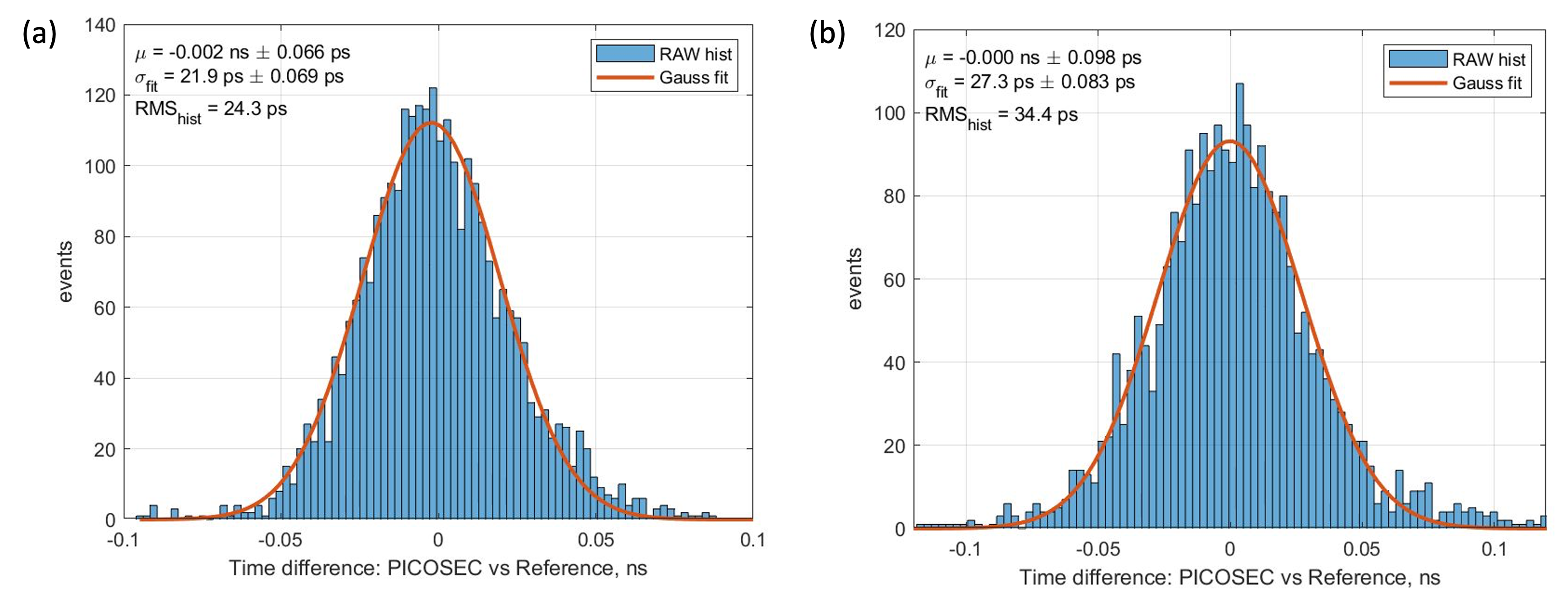
The measurements of the time resolution for different thicknesses of B4C photocathodes were performed during the RD51 test beam campaigns. A single-channel non-resistive PICOSEC MM prototype was used to test the samples. Different photocathode thicknesses ranging from 2 nm to 14 nm were tested. The best timing response was obtained for a 12 nm thick B4C sample. First measurements from a single-pad detector with 120 µm preamplification gap equipped with a 12 nm thick B4C photocathode, presented in Fig. 4, showed a time resolution below = 25 ps. The measurements performed 20 hours later presented a time resolution below = 35 ps. The 12 nm thick B4C sample demonstrated the best time resolution achieved for robust photocathode materials studied up to now.
6 Conclusions
The work described in this paper focused on improving the robustness aspects of the PICOSEC MM detectors, including the integration of resistive MM and robust photocathodes, while maintaining good time resolution. The excellent timing performance below = 20 ps for an individual pad obtained with the 10×10 cm2 area resistive PICOSEC MM of 20 M/ equipped with a CsI photocathode showed no significant time resolution degradation as a result of adding a resistive layer. Measurements performed with a scalable readout chain including the SAMPIC digitiser resulted in a successful readout of a multi-channel detector. A single-pad prototype equipped with a 12 nm thick B4C photocathode presented a time resolution below = 35 ps, opening up new possibilities for detectors with robust photocathodes. The results made the concept more suitable for the experiments in need of robust detectors with precise timing. Developments towards applicable detectors are ongoing. The challenges include stable operation in intense beams with resistive MM Multipad and operating a PICOSEC MM detector with a 10×10 cm2 area B4C photocathode. Scaling up the PICOSEC MM detector by tiling 10×10 cm2 modules or the development of larger prototypes are potential next development steps.
Acknowledgments
We acknowledge the support of the CERN EP R&D Strategic Programme on Technologies for Future Experiments; the RD51 collaboration, in the framework of RD51 common projects; the Cross-Disciplinary Program on Instrumentation and Detection of CEA, the French Alternative Energies and Atomic Energy Commission; the PHENIICS Doctoral School Program of Université Paris-Saclay, France; the Program of National Natural Science Foundation of China (grant number 11935014); the COFUND-FP-CERN-2014 program (grant number 665779); the Fundação para a Ciência e a Tecnologia (FCT), Portugal (CERN/FIS-PAR/0005/2021); the Enhanced Eurotalents program (PCOFUND-GA-2013-600382); the US CMS program under DOE contract No. DE-AC02-07CH11359.
References
- [1] J. Bortfeldt, et al., for the PICOSEC Micromegas Collaboration, PICOSEC: Charged particle timing at sub-25 picosecond precision with a Micromegas based detector, Nucl. Instrum. Methods A 903 (2018) 317–325.
- [2] S. Aune, et al., for the PICOSEC Micromegas Collaboration, Timing performance of a multi-pad PICOSEC-Micromegas detector prototype, Nucl. Instrum. Methods A 993 (2021) 165076.
- [3] M. Lisowska, et al., for the PICOSEC Micromegas Collaboration, Sub-25 ps timing measurements with 10×10 cm2 PICOSEC Micromegas detectors, Nucl. Instrum. Methods A 1046 (2023) 167687.
- [4] L. Sohl, Development of PICOSEC-Micromegas for fast timing in high rate environments, PhD dissertation, Université Paris-Saclay, 2020; available at https://hal-universite-paris-saclay.archives-ouvertes.fr/tel-03167728/ (accessed on March 31st, 2023).
- [5] L. Sohl, Spatial time resolution of MCP-PMTs as a t0-reference, Nucl. Instrum. Methods A 936 (2019) 583-585.
- [6] A. Utrobicic, et al., for the PICOSEC Micromegas Collaboration, A large area 100 channel PICOSEC Micromegas detector with sub 20 ps time resolution, The 7th International Conference on Micro Pattern Gaseous Detectors, 11-16 December 2022.
- [7] D. Breton, et al., Measurements of timing resolution of ultra-fast silicon detectors with the SAMPIC waveform digitizer, Nucl. Instrum. Methods A 835 (2016) 51-60.