Upside down: affordable high-performance motion platform
Abstract
Parallel robots are capable of high-speed manipulation and have become essential tools in the industry. The proximal placement of their motors and the low weight of their end effectors make them ideal for generating highly dynamic motion. Therefore, parallel robots can be adopted for motion platform designs, as long as end effector loads are low. Traditional motion platforms can be large and powerful to generate multiple g acceleration. However, these designs tend to be expensive and large. Similar but smaller motion platforms feature a small work range with reduced degrees of freedom (DoFs) and a limited payload. Here we seek a medium-sized affordable parallel robot capable of powerful and high-speed 6-DoF motion in a comparably large workspace. This work explores the concept of a quadruped robot flipped upside-down, with the motion platform fixed between its feet. In particular, we exploit the high-power dynamic brushless actuation and the four-leg redundancy when moving the motion platform. We characterize the resulting motion platform by tracking sinusoidal and circular trajectories with varying loads. Dynamic motions in 6 DoFs up to 10 Hz and 10 mm amplitude are possible when moving a mass of 300 grams. We demonstrate single-axis end-effector translations up to 20 mm at 10 Hz for higher loads of 1.2 kg. The motion platform can be replicated easily by 3D printing and off-the-shelf components. All motion platform-related hardware and the custom-written software required to replicate are open-source.
1 Introduction
Motion platforms are designed to move objects in 3D space in a given workspace. 6-degree of freedom (DoF) motion platforms are widely adapted to simulate the complex and dynamic motions of aircraft, vehicles, ships, entertainment platforms, and research test benches [1, 2].
Multiple approaches for generating 6-DoF motion have been proposed, such as using industrial 6 DoF robotic arms [3], crank arm platforms [1, 4], linear actuators [5, 6], and parallel robots. Parallel robots are ”closed-loop mechanical structures whose mobile platforms are linked to the base by independent kinematic chains, presenting good potential in terms of accuracy, rigidity, and ability to manipulate large loads with positioning errors” [7]. Thanks to their high rigidity, robustness against external force and good payload abilities[8, 9, 10, 11], parallel robots are often adopted for high acceleration motion platform designs.
Delta robots [12, 13, 14] and Stewart-Gough platforms [8, 9] are well known solutions. Delta robots feature three translational DoFs where the end-effector stays parallel to the base of the robot, allowing for high-speed pick and place tasks [14, 15, 16]. Stewart-Gough platforms consist of a platform connected to a fixed base using six extensible legs of adjustable lengths, which determine the position and orientation of the attached platform [8]. Despite their popularity, such robots are still costly and less well suited for non-industrial applications.
High performance 6-DoF motion platforms are more expensive with price tags above 100k €, as they are intended for simulating the motion of large objects. These commercial motion platforms are operated with proprietary, custom-designed software. We found that limited affordable options for motion simulation exist for research. Low-end motion platforms are often designed for education purposes, and deliver insufficient acceleration in case of high-range motions and higher mass objects. Hence, researchers have developed motion platforms from off-the-shell components [17]. Clearly, building an entire motion platform and its software framework from scratch is time-consuming.
Here, we were looking for open-source robot platforms as solutions to build an affordable, customized motion platform (LABEL:{fig:control_envs}). For our specific need of high acceleration motion simulation, we could not find designs at affordable prices. But as a robotic research laboratory, we work daily with dynamically running legged robots that are open-source available. Consequently, we build our solution around the recently open-sourced quadruped robot Solo [18]. Solo robot is capable of highly dynamic movements, such as high vertical jumps, and even back flips. Its highly dynamic robot motion is made possible by the robot’s powerful brushless motors controlled by field oriented control (FOC). By flipping the robot upside down, its four legs can be used to actuate a motion platform in 6-DoF. The four-legged SOLO robot (SOLO-12) features in sum twelve motors with 3 motors per leg; two shoulder actuators, and one knee actuator. A comparably low gearbox ratio (9:1) allows for high accelerations, and powerful brushless motors supply high torque output. The Solo robot is designed with off-the-shell components and made mostly from 3D printing parts, which lead to comparably low production and maintenance costs.
In this work, we present the resulting high-performance and affordable 6-DoF motion platform hardware design and its software and control framework. Our hardware design is based on the quadruped robot Solo-12. As we flip the Solo robot upside down, making the legs face upwards and attach to our custom designed platform, we created a parallel robot with closed-loop kinematic chains. We developed a multibody simulation model of the robot in the PyBullet environment [19], which we connect with our robot control framework. Both hardware design and software framework are open-source available. The proposed motion platform achieves highly dynamic movement. It tracks a sinusoidal trajectory up to Hz with mm translation amplitude, for motion platform loads of 0.3 kg. Higher loads of 1.2 kg can be moved at 2 Hz, for a motion range of mm translation or degrees rotation. To the best of our knowledge, there is no open-source 6-DoF motion platform capable of such highly dynamic movement, with a comparable price tag.
2 Robot Framework
2.1 Hardware Framework
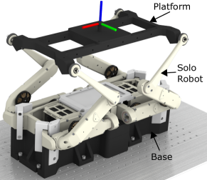
The hardware framework consists of three main components (LABEL:{fig:solo_robot_labelled}); a quadruped robot Solo [18], a light-weight motion platform attached to the robot’s legs, and a base and fixture to mount the SOLO robot body to the table. The complete setup requires a total installation space with a height of cm (z-axis), length of cm (x-axis), and a width of cm (y-axis). Safety margins are included. The maximum workspace of the platform is x-axis , y-axis , and z-axis for translation; 30 degrees for roll, yaw and pitch.
The Solo robot [18] is an open source modular robot. The SOLO actuator module features a dual-stage timing belt transmission, a high-resolution optical encoder, and a brushless motor. Each SOLO joint can output Nm joint torque, and is controlled at up to [18].
The platform is mounted to the robot’s feet with ball joints (IGUS KGLM-05). Ball joint allow a maximum pivot angle of 30 degrees. We press-fit the ball joints into the robot’s feet and secured them with M4 nuts to the platform. The platform itself is 3D printed from PLA material. The platform provides multiple mounting points for attaching payloads. An inertia measurement unit (IMU, 3DM-CX5-25) is mounted at the bottom of the platform. With the IMU, we record end effector ground truth data. To fix the robot body during movement, we designed a base that is screwed on top of an optic table. We replaced the lower center plate of the original robot with our mounting plate. CAD models of the platform and the base are available on GitHub https://github.com/nayan-pradhan/solo-6dof-motion-platform. The cost for the 3D printing parts of the motion platform’s base, clamps, the platform, and the connecting ball joints amounts to approximately €. The material cost of the SOLO robot is approximately € without an inertial measurement unit (IMU), and € with an IMU (Lord Microstrain 3DM-CX5-25).
2.2 Software Framework
We custom-wrote a software framework to control platform motion. This open-source software package offers full control for 6 DoF motion. In addition to the physical robot control, we also offer a PyBullet-based simulation environment to evaluate the performance of the platform. The framework features two options of logging the platform pose - through the physically mounted IMU or through forward kinematic calculations of joint angles. Because of the high price of higher quality IMUs, the forward kinematic calculation is the low-cost option. The software package is mainly written in Python3. The software framework is built modular such that users may update, add, or remove parts of the module as long as the input format is maintained. The detailed documentation can be found in our GitHub repository: https://github.com/nayan-pradhan/solo-6dof-motion-platform.
Our software framework consists of four main modules, shown in LABEL:{fig:flowchart_software}:
-
1.
Platform Trajectory Generation
-
2.
Inverse Kinematics Tool
-
3.
Control Environment
-
4.
Post Processing

2.2.1 Platform Trajectory Generation
The Platform Trajectory Generation module generates the target pose of the platform. We implemented four base trajectory options:
Sine Trajectory: A sine wave trajectory of specified run time (seconds), wait time (seconds), type of movement (translation/rotation), frequency (Hz), amplitude (mm/deg), and x, y, z axis offsets (mm) is generated.
Arbitrary Trajectory: A smooth linear interpolation of specified time (seconds) between a series of arbitrary target positions (mm) and orientations (deg) is generated.
Step Trajectory: A step function in a specified position (mm) and orientation (deg) is generated. As such, a step response is useful for tuning controller gains.
Circular Trajectory: A circular trajectory of specified radius of translation (mm), angle of rotation (deg), number of rounds, frequency of rotation, direction of translation and rotation (clock-wise/counter-clock-wise), and ability to enable/disable translation and/or rotation is generated.
2.2.2 Inverse Kinematics Tool
The Inverse Kinematics Tool module takes platform target trajectories generated from LABEL:{sec:platform_trajectory_generation} as the input and calculates target joint angles for each joint using inverse kinematics. We use PyBullet [20] for the inverse kinematics calculation. Additionally, we provide an API for custom inverse kinematics packages such as Robotics Toolbox [21].
2.2.3 Control Environment
The Control Environment module takes the target joint angles generated from LABEL:{sec:inverse_kinematics_tool} as the input and starts the platform motion. Our software framework contains two control environments:
-
1.
PyBullet Simulation Environment
-
2.
Solo Environment
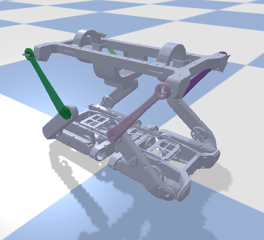
The PyBullet Simulation Environment (LABEL:{fig:pybullet_solo_env}) executes joint commands in simulation at . The control update frequency is limited by PyBullet. The simulation environment loads the URDF models of the Solo robot and the platform. It creates constraints between foot joints and platform corners. The PyBullet simulation can be used to test new algorithms and implementations without wearing the physical robot setup out.
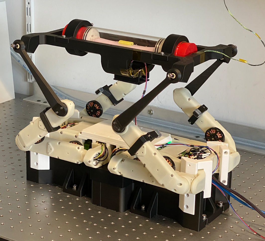
The Solo Environment (LABEL:{fig:solo_solo_env}) is used to control our physical motion platform at . The Solo environment initializes the robot, calibrates the robot, executes the desired motion trajectory, and logs the all sensor data.
2.2.4 Post Processing
The Post Processing module loads the stored data, processes data, and plots previews.
Target trajectories and sensor readings from Sections 2.2.1, 2.2.2, and 2.2.3 are loaded. We calculate the pose of the platform from robot joint angles.
We do this by first calculating the position of the foot links in the Solo robot (our end-effectrs) for each leg using the loaded joint angles and the measured distances between joints from the CAD model. We define a dummy ball joint at the foot links (end-effectors). We then construct a vector from the front left ball joint to the back right ball joint and another vector from the front right ball joint to the back left ball joint. We compute the intersection point between the two constructed vectors. This intersection point represents the x and y values of the platform center. In order to get the correct z value, we have to add an offset in z, which we get from the CAD model.
To get the orientation of the platform we calculate three more vectors. First we calculate the vector from the front left to the back left ball joint position. This vector represents the x direction of our platform. By calculating the vector from the front left to the front right we get the y direction. Lastly we get the z direction by building the cross product of the two vectors we calculated earlier. To get the platform orientation we use the Rotation class from scipy.spation.transform. We use the method align_vectors() where we get the transformation matrix between the global coordinate system and our three calculated vectors representing the platform axes. This transformation matrix represents our platform orientation. For easier understanding we chose to use the Euler angle representation.
The linear and angular velocity and acceleration at the center of our platform is derived using the calculated positions and orientations. This provides the use the option to record the position, velocity, and acceleration of the platform without purchasing an expensive IMU. The calculated pose is filtered using a Butterworth low pass filter with a cutoff frequency of .
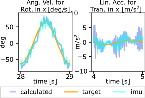
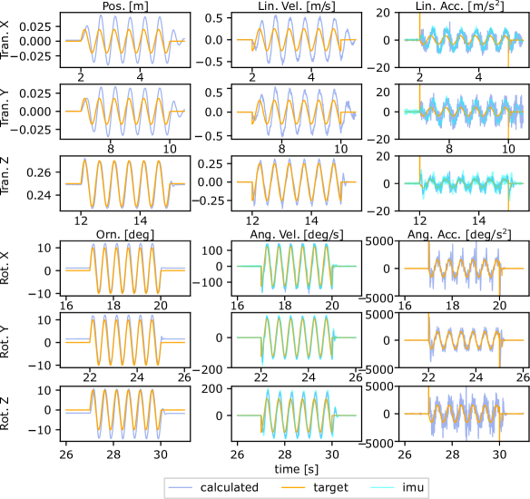
We validate our calculated data with the raw IMU data. LABEL:{fig:imu_overlay} shows an example of the calculated, target, and measured IMU values in x-axis direction for a sinusoidal motion of frequency Hz and amplitude mm/ deg.
The data preview module showing desired plots and graphs is loaded automatically after the data is processed. This can also be executed independently for quick visualization of the latest data.
3 Experimental Benchmarking and Results
In this section, we present benchmarking experiments and results with our 6-DoF motion platform hardware. In order to benchmark the results, we compare the commanded and target values with the calculated and actual values.
We benchmark our setup with two motion trajectories:
-
1.
Sinusoidal Trajectory
-
2.
Circular Trajectory
3.1 Sinusoidal Trajectory
We use sinusoidal trajectory as one of the benchmarks because we can test and validate a wide range of dynamic motions with varying amplitude and frequencies on each DoF. We use a target sine trajectory in each of the 6 DoF with a sequence run-time of seconds, wait-time of seconds, frequency of Hz, translational amplitude of mm and rotational amplitude of degrees.
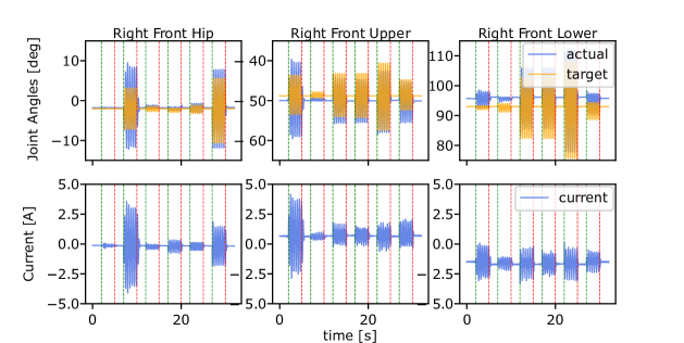
3.1.1 Joint Angles
We compare the actual robot joint angles to the target joint angles from the right front leg, and show the current measurement (in linear relation to torque output) of the respective motor LABEL:{fig:solo_fr_jointangles}. The Root Mean Squared Error (RMSE) between the target and actual joint angles is calculated as shown in LABEL:{tab:msd_jointangles_sine}. The average RMSE for the right leg was degrees, showing good tracking results. We notice a constant offset in the right front upper and right front lower joint angles, which is caused by gravity. In this control, the influence of gravity is not modeled, and hence not compensated for.
| Joint Name | RMSE |
|---|---|
| Right Front Hip Joint | deg |
| Right Front Upper Joint | deg |
| Right Front Lower Joint | deg |
| Average of Right Leg Joints | deg |
3.1.2 Platform Pose
A second approach to benchmark our motion platform is to compare the target pose to the calculated pose (LABEL:{sec:post_processing}), as shown in LABEL:{fig:solo_platform_pose}.
We observed overshoot motions in x, y translation and in x rotation. The overshoot motions are associated with the joint overshoots as in LABEL:{fig:solo_fr_jointangles}. The pose tracking RMSE is documented in LABEL:{tab:msd_platform_pose_sine}. We find that the largest RMSE of mm happens during x-axis translation, followed by mm in the y-axis translation. We believe fine-tuning the controller gains can improve the tracking performance.
In a set of additional experiments, we increased the platform’s sine wave motion frequency to identify the setup’s maximum acceleration. We stopped experiments at with an amplitude of . At these loads, the motor current is reaching the limit of . At , the platform movement becomes relatively violent at maximum acceleration of , and pose tracking quality decays much. Nevertheless, this experiment demonstrates the high acceleration capacity of the proposed motion platform.
| Platform Traj. | Motion Type | Motion Axis | RMSE |
|---|---|---|---|
| x | mm | ||
| Translation | y | mm | |
| z | mm | ||
| Sine | Average Translation | xyz | mm |
| Trajectory | x | deg | |
| Rotation | y | deg | |
| z | deg | ||
| Average Rotation | xyz | deg |
3.2 Circular Trajectory
We use a circular trajectory to test dynamic motion tracking of multiple DoF movements simultaneously. The circular trajectory generation method in 2.2.1 to generate a simultaneous clock-wise circular translation and rotation motion on the z-axis in a motion frequency of Hz (LABEL:{fig:circular_plot}).
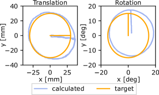
The platform can follow the target trajectory as shown in LABEL:{fig:circular_plot}. We notice deviations from the nominal path, which we connect to minor calibration errors. The platform follows a smooth path consistently over 20 cycles, with a satisfactory and repeatable precision. The accuracy of path tracking is documented in Table III, which should be improved further. We also notice relatively high RMSE on z axis translation, which can be improved by implementing a gravity compensation function.
The experiment videos of the motion platform are available at https://youtu.be/thXPA2MYcQw.
| Platform Traj. | Motion Type | Motion Axis | R.M.S.E |
|---|---|---|---|
| x | mm | ||
| Translation | y | mm | |
| z | mm | ||
| Circular | Average Translation | x, y, z | mm |
| Trajectory | x | deg | |
| Rotation | y | deg | |
| z | deg | ||
| Average Rotation | x, y, z | deg |
4 Conclusion
In this work, we propose a high-performance low-cost motion platform design. The motion platform hardware is centered around the four legs of the quadruped robot Solo. Its legs hold a platform, creating a parallel robot. Besides the quadruped robot, our setup requires only few, simple-to-implement 3D printing parts, and a few off-the-shell components like bearings and screws. Driven by the four legs and 12 motors simultaneously, this motion platform provides high acceleration, up to at a platform loading of 300 grams. Our systematic benchmarking on sinusoidal and circular trajectories with 1.2 kg platform loading demonstrates good tracking performance and workspace. We custom-developed a control framework and a PyBullet-based simulation model of the motion platform, allowing for real-time control and data logging up to . The hardware design and software packages are fully open source available at https://github.com/nayan-pradhan/solo-6dof-motion-platform. We envision our robot design will support barrier free research, catalyzing future robot development and application.
Acknowledgments
The authors thank the International Max Planck Research School for Intelligent Systems (IMPRS-IS) and the China Scholarship Council (CSC) for supporting An Mo. This work was funded by the Max-Planck Institute for Intelligent Systems’ Grassroots project and the Deutsche Forschungsgemeinschaft (DFG, German Research Foundation), project 449912641. The authors thank Felix Grimminger and Huanbo Sun for supporting the hardware development.
References
- [1] Ming-Yen Wei “Design and Implementation of Inverse Kinematics and Motion Monitoring System for 6DoF Platform” In Applied Sciences 11.19 MDPI, 2021, pp. 9330
- [2] Bin Li et al. “Design and simulation analysis of 6-DOF electric platform” In IOP Conference Series: Materials Science and Engineering 563, 2019, pp. 052059 IOP Publishing
- [3] Jamshed Iqbal, R Ul Islam and Hamza Khan “Modeling and analysis of a 6 DOF robotic arm manipulator” In Canadian Journal on Electrical and Electronics Engineering 3.6, 2012, pp. 300–306
- [4] Alexey Fomin, Anton Antonov, Victor Glazunov and Yuri Rodionov “Inverse and forward kinematic analysis of a 6-DOF parallel manipulator utilizing a circular guide” In Robotics 10.1 MDPI, 2021, pp. 31
- [5] Eric L Faulring, J Edward Colgate and Michael A Peshkin “A high performance 6-DOF haptic cobot” In IEEE International Conference on Robotics and Automation, 2004. Proceedings. ICRA’04. 2004 2, 2004, pp. 1980–1985 IEEE
- [6] K Fujimoto, Satoshi Tadokoro and T Takamori “Development of a 6-dof direct-drive wrist joint by pneumatic linear actuator drive” In [Proceedings] IECON’90: 16th Annual Conference of IEEE Industrial Electronics Society, 1990, pp. 427–432 IEEE
- [7] Stefan Staicu “Dynamics of Parallel Robots” Springer, 2019
- [8] Xiao-Shan Gao, Deli Lei, Qizheng Liao and Gui-Fang Zhang “Generalized Stewart-Gough platforms and their direct kinematics” In IEEE Transactions on Robotics 21.2 IEEE, 2005, pp. 141–151
- [9] Amir Ghobakhloo, M Eghtesad and M Azadi “Position control of a Stewart-Gough platform using inverse dynamics method with full dynamics” In 9th IEEE International Workshop on Advanced Motion Control, 2006., 2006, pp. 50–55 IEEE
- [10] Haiqiang Zhang et al. “Forward kinematics and workspace determination of a novel redundantly actuated parallel manipulator” In International Journal of Aerospace Engineering 2019 Hindawi, 2019
- [11] M Ratiu and DM Anton “A brief overview of parallel robots and parallel kinematic machines” In IOP Conference Series: Materials Science and Engineering 898, 2020, pp. 012007 IOP Publishing
- [12] François Pierrot, C Reynaud and Alain Fournier “DELTA: a simple and efficient parallel robot” In Robotica 8.2 Cambridge University Press, 1990, pp. 105–109
- [13] L Rey and R Clavel “The delta parallel robot” In Parallel Kinematic Machines Springer, 1999, pp. 401–417
- [14] Ilian Bonev “Delta parallel robot-the story of success” In Newsletter, available at http://www. parallelmic. org, 2001
- [15] Jean-Pierre Merlet “Parallel robots” Springer Science & Business Media, 2005
- [16] Hayley McClintock et al. “The milliDelta: A high-bandwidth, high-precision, millimeter-scale Delta robot” In Science Robotics 3.14 American Association for the Advancement of Science, 2018, pp. eaar3018
- [17] An Mo, Viktoriia Kamska, Fernanda Bribiesca-Contreras and Alexander Badri-Spröwitz “Open electronics for a biophysical model for intraspinal mechanosensing in avians” In Society for Experimental Biology, 2021
- [18] Felix Grimminger et al. “An open torque-controlled modular robot architecture for legged locomotion research” In IEEE Robotics and Automation Letters 5.2 IEEE, 2020, pp. 3650–3657
- [19] Erwin Coumans and Yunfei Bai “PyBullet, a Python module for physics simulation for games, robotics and machine learning”, http://pybullet.org, 2016–2021
- [20] PyBullet “Bullet Real-Time Physics Simulation” [Online; accessed 2022-10-27], https://pybullet.org/wordpress/, 2022
- [21] Peter Corke and Jesse Haviland “Not your grandmother’s toolbox–the Robotics Toolbox reinvented for Python” In 2021 IEEE International Conference on Robotics and Automation (ICRA), 2021, pp. 11357–11363 IEEE