Dispersion engineering of infrared epsilon-near-zero modes by strong coupling to optical cavities
Abstract
Epsilon-near-zero (ENZ) materials have recently emerged as a promising platform for infrared nanophotonics. A significant challenge in the design of ENZ-based optics is to control the dispersion of ENZ modes, which otherwise have a flat profile near the ENZ frequency. Strong coupling with an optical cavity is a promising approach to ENZ dispersion engineering, which however has limitations due to the lack of tunability or nanofabrication demands of the cavity employed. Here, we theoretically and numerically show that much of the limitations of previous demonstrations can be overcome by strongly coupling the ENZ mode to an unpatterned Fabry-Perot cavity. We demonstrate this unprecedented ENZ dispersion control in coupled cavities by designing tunable infrared polarizers that can absorb s and reflect p-polarized components, or vice versa, for almost any oblique angle of incidence, i.e. omnidirectional polarizers. The feasibility of active control is also demonstrated using a phase change material within the cavity, which predicts dynamic switchability of polariton dispersions across multiple resonant levels at mid-infrared wavelengths. These results are expected to advance the current understanding of strongly coupled ENZ interactions and demonstrate their potential in tailoring dispersions for active and passive control of light.
I Introduction
Coherent optical interactions lead to unusual phenomena such as Fano resonances [1], electromagnetically induced transparency [2], extraordinary optical transmission [3], surface lattice resonances [4], and strong coupling [5]. Strong coupling (SC) is characterized by a splitting of resonances when the frequencies of mutually coupled resonators or cavities are brought close to each other. This effect is typified by an anti-crossing of the cavity dispersions, which split to form two distinct (upper and lower) polariton branches [6]. The frequency separation at the anti-crossing point, known as Rabi splitting, signifies the strength of the mutual interaction, and SC can be experimentally observed in optical systems where the Rabi splitting is larger than the line-widths of individual resonances [7, 8, 9, 10, 11, 12]. As a result of this splitting, SC opens up unique possibilities in engineering spectral response and dispersion in nanophotonics by finely tailoring polariton dispersions.
The introduction of SC has been proposed as an effective tool for exploiting the unique properties of epsilon-near-zero (ENZ) materials [13, 14]. ENZ materials have a vanishing or near-zero permittivity ( 0) at a particular wavelength and have attracted interest as a novel platform for exotic light-matter interactions [15]. Near the zero-epsilon wavelength (), ENZ materials can exhibit extreme field concentration and enhancement, strong optical non-linearities and perfect absorption [16, 17, 18, 19, 20, 21]. Moreover, the optical modes supported in ultrathin ENZ films, called ENZ modes [22], show strong field enhancements within low mode volumes, and have been utilized in active opto-electronic devices and ultrafast optical modulation [23, 24, 25, 26, 27]. Notably, the flat spectral dispersion near results in a zero group velocity, low propagation lengths, and it overall limits control over the operating frequencies or angles [28]. Earlier efforts in spectral shaping and tailoring of the ENZ mode dispersion explored its strong coupling with optical cavities such as quantum wells [14], gap plasmon modes [29], metasurfaces [30], phonon polaritons in polar dielectrics [31], plasmonic nanoantennas [32, 33, 34] and plasmon polaritons [28], which have helped realize negative refraction [13], hybrid plasmonic modes [28], and enhanced optical non-linearities [35]. However, the ability to tailor dispersions in strongly coupled systems is often hampered by the low tunability of the employed optical cavities. Moreover, the use of metasurfaces and plasmonic resonances involve nanofabrication processes that increase the cost and complexity of the system. Therefore, planar, lithography-free structures with large field enhancements and strong tunability need to be further explored as potential platforms to exploit strong coupling with ENZ modes.
Here, we overcome the limitations of previous strongly coupled ENZ designs to demonstrate unprecedented tailoring of polariton dispersions at infrared wavelengths by coupling to a Fabry-Perot (FP) cavity. FP cavities have long been the workhorse of strong coupling research, having been employed in polariton-enhanced transport [36], chemical reactivity [37], and condensation [38]; however, to the best of our knowledge, coupling of ENZ modes to a FP cavity has not been addressed earlier. Using an analytical approach, we identify the factors that control the coupling strength of the two modes, revealing that the polariton properties are mediated by an interplay of the near field of the ENZ and FP cavities as well as the ENZ thickness. In particular, we demonstrate the potential for ENZ dispersion engineering and complex spectral shaping in our system by designing planar, multilayer, coupled cavities that act as angle-independent, nearly omnidirectional polarizers with a controllable operation wavelength in the near and mid-infrared. Finally, to demonstrate their potential applications, active tunability of multilevel polariton dispersions is explored employing a phase change material. Our results not only demonstrate and characterize the extent to which ENZ mode dispersions can be engineered but also provide a simple configuration where ENZ light-matter interactions can be readily tailored for the versatile design of infrared optical components [39] and thermal emission control [40].
II Results and discussion
II.1 Strong coupling of ENZ and FP modes
To investigate the possibility of strongly coupled resonances in a planar geometry, a structure composed of a dielectric (PMMA) and an ENZ layer (doped cadmium oxide, CdO) sandwiched between two metallic mirrors (Ag) is considered. The permittivity or refractive index data used in this work and their model parameters are given in section ’Materials and Methods’ and plotted in Figure S1 in Supplementary Materials. The individual or ’bare’ resonances i.e. with only the dielectric between the mirrors (FP cavity: Ag-PMMA-Ag) and only the ENZ medium between the mirrors (ENZ mode: Ag-CdO-Ag) are first separately analyzed. The inset to Figure 1a schematically shows the FP structure, where the PMMA dielectric layer (thickness ) is sandwiched between the Ag substrate and a thin Ag layer of thickness . The thickness of the top metallic layer is comparable to its skin depth to allow coupling of light incident from the top-most air medium into the FP cavity. Throughout this work, the Ag substrate is assumed to be semi-infinite with transmittance = 0. Figure 1a shows the calculated color map of reflectance () of the FP cavity for p-polarized light, i.e. , as a function of angle of incidence () and wavelength () in the near-IR (1500 nm to 2200 nm). The thicknesses are set as = 670 nm and = 20 nm. The dispersion of the FP cavity is evident as a sharp dip in reflectance (bright region), and the wavelength of maximum absorption ( = ) varies over approximately a 500 nm range as is varied from 0 to 90 degrees in Figure 1a. Figure 1b shows for light incident from air onto the ENZ mode structure. Here, a CdO layer with a of 1900 nm and thickness = 20 nm is sandwiched between the Ag mirrors (see inset). The plot shows a flat dispersion in the vicinity of , indicating the excitation of the radiative ENZ mode known as Berreman mode [22]. Importantly, the dispersions of the FP cavity and the ENZ mode can cross near , leading to the possibility of strong coupling. Figure 1c shows for the combined FP cavity-ENZ mode structure (Ag-PMMA-CdO-Ag, hereafter ENZ-FP cavity; see inset), revealing substantially modified absorption features. A clear anti-crossing of resonances is observed near , characterized by a splitting of the overall dispersion into an upper and lower branch. This opens up a highly reflecting window around as indicated by the arrow in Figure 1c. The Rabi splitting ( = 55 meV) satisfies the criterion for strong coupling [6, 41], which is given as , where 12 meV and 25 meV are full widths at half maximum (FWHM) of the bare FP and ENZ resonances at the crossing point, respectively. The corresponding reflectance maps of the cavities for s-polarized light () are shown in Figure S2, where the Berreman mode cannot be excited and only the FP resonance is observed in the ENZ-FP cavity. This clearly indicates that ENZ mode excitation is an integral part of the strongly coupled interaction observed in . Further, it is seen that the features in may be effectively employed as a reference against which to compare the signatures of SC in .

To further understand the origin of the splitting, the frequency-wavenumber dispersion relations of the upper and lower branches are modeled by the following expression [28]:
| (1) |
where denotes the dispersion relation of the upper (+) and lower (-) branches of the ENZ-FP cavity, is the dispersion relation of the bare FP cavity, is the dispersion relation of the bare ENZ mode, is the in-plane wave number and is the incident free-space wave number. The details of the calculation of and are given in Section S3. The strong coupling model in Equation (1) is presented in Figure 1d. and are plotted as dashed curves, while the upper and lower branches are plotted as solid curves, calculated using estimated from Figure 1c. For convenience, the point where the bare dispersions cross is referred to by (, ). The model qualitatively reproduces the observed anti-crossing behavior and splitting around this point well. It also shows how the upper and lower branches asymptotically tend to the bare dispersions away from (, ), validating the strongly coupled nature of interaction of the ENZ mode and the FP cavity at the crossing point. The anti-crossing behavior is further characterized in Supplementary Figure S4, which clearly shows mode splitting around and support the strongly coupled interaction picture in the ENZ wavelength regime.
II.2 Factors determining strong coupling
In this section, the factors affecting the strength of SC are systematically investigated. Strongly coupled systems have been classically described using a coupled harmonic oscillator model where the energy splitting depends on a coupling term in the coupled mode equations [6]. In optical systems, this coupling can be ascribed intuitively to the spatial overlap between electric fields of the interacting resonances at () [10]. In the case of the ENZ-FP cavity, this can be written as [28]
| (2) |
where is the electric field associated with the FP cavity, is the field of the ENZ mode, r is the position vector, the integral is over the cavity volume , and the fields are evaluated at (). The ratio of the frequency splitting and the zero-epsilon frequency ,
| (3) |
can be used to further quantify the coupling strength between the ENZ mode and the FP cavity [42]. Several approximations can be made to simplify the analysis of Equation (2). First, the electric field of the ENZ mode is dominantly out-of-plane (along z direction, see coordinate axes in Figure 1a) [43]. Second, the out-of-plane ENZ mode fields in the ENZ-FP cavity are strongly confined to the interior of the ENZ layer, which results in the overlap integral being negligible outside the layer. Third, the field inside the ENZ layer is spatially uniform along z [43], allowing it to be taken outside the integral. These considerations allow Equation (2) to be simplified as
| (4) |
where the subscript ’z’ denotes the out-of-plane component of the electric fields and the integral is now limited to the thickness of the ENZ layer.
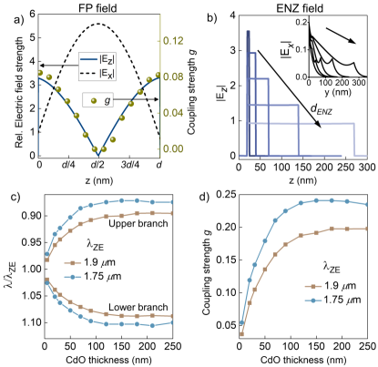
Based on Equation (4), the dependence of coupling strength on the FP cavity field is investigated first. Figure 2a (left axis) plots the components of electric field as a function of vertical position inside the bare FP cavity. The fields are plotted for the FP cavity in Figure 1 ( = 670 nm, = 20 nm), at the point (). The plot shows that while the in-plane component () is minimum at the surface of the Ag mirrors, the out-of-plane component () is maximum as a consequence of the Fresnel reflection phase imparted by the perfect electric conductor-like metal. Equation (4) suggests that the strong coupling interaction, which is expected to be mediated by the z components, will be maximized when the location of the ENZ layer is at the bottom (or top) of the ENZ-FP cavity (where is maximum) and minimized when the ENZ layer is at the center of the cavity. To verify this, the coupling strength for the ENZ-FP cavity in Figure 1 is calculated as a function of the vertical position of the ENZ layer in the cavity and is plotted on the right axis of Figure 2a. Here, the ENZ thickness is a constant and only its position within the cavity is varied. It is evident that is maximum when the ENZ layer is at the surface of the Ag mirrors and is zero when it is placed at the center of the cavity, in close correlation with the strength of of the FP cavity. Note that this is in contrast to most observations in literature where the strong coupling is maximum when the active layers with dominantly in-plane fields or dipole moments are placed at the center of the FP cavity [44].
Having identified the role of the out-of-plane FP field strength, the dependence of on and are considered next. To illustrate this, the wavelength splitting of the upper and lower branches of the ENZ-FP cavity are calculated for different ENZ thicknesses. Figure S5 plots of the ENZ-FP cavity in Figure 1 for different ENZ thicknesses from 0 to 250 nm. From this, the wavelength splitting is calculated after identifying the respective cross-over points of the bare dispersions for each thickness. Figure 2c plots the upper and lower polariton wavelengths (normalized to ) against , calculated for = 1750 and 1900 nm. The splitting is observed to initially increase with ENZ thickness but saturates around 100 nm for both values of . Figure 2d further plots the variation of with , clearly showing the initial sharp increase in the coupling strength and its saturation at larger values of ENZ thickness for both the values of . To understand this, two cases are analyzed here: I. is a small fraction of the overall cavity thickness () and II. . In case I, Equation (4) can be further simplified by assuming that the spatial variation in is negligible over the scale of the ENZ layer thickness, bringing it outside the integral. This yields , which indicates that increases in proportion to when the ENZ thickness is low enough. More accurately, is decided by the inter-relation between and its mode field, . Figure 2b plots inside the bare ENZ cavity by varying from 5 nm to 250 nm, at () where it crosses the FP dispersion of Figure 1. The component is seen to be spatially uniform even for the thickest 250 nm CdO layer. The corresponding plots of are shown in the inset, which are an order of magnitude weaker than , validating the assumptions stated earlier that the field in the ENZ mode is dominantly out-of-plane and spatially uniform in nature. Notably, decreases as increases, which means that the expected increase in coupling strength with due to a larger interacting volume would be tempered by the decreasing ENZ mode field strength. Thus, the coupling strength will be determined by a trade-off between the larger interaction volume at large and the stronger interacting electric field at small in the ENZ layer.
The initial increase in coupling strength in Figure 2d follows from the expected dependence of on (larger interaction volume) discussed in case I. The increase is however sub-linear, pointing to the effect of decreasing that reduces the interaction strength. This does not, however, explain the saturation of at large , for which case II () is considered. Here, it is evident that the variation in over the scale of the ENZ layer thickness is no longer negligible. In fact, increasing the ENZ thickness can be imagined to be similar to adding ENZ layers sequentially towards the center of the FP cavity. As discussed earlier, this would contribute negligibly to the overall coupling strength due to the decay of towards the center. Therefore, effectively only the ENZ layers near the surface of the Ag mirrors will be involved in SC, which qualitatively explains why saturates at large values of .
II.3 Wide-angle polarizer design
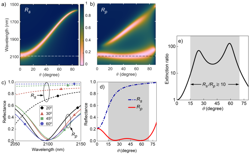
Having identified the control parameters for strong coupling in an ENZ-FP cavity, in this section, the design of infrared wide-angle polarizers is demonstrated to highlight the extent of dispersion engineering possible in this system. Figure 3a,b shows the reflectance maps and of an Ag-PMMA-CdO-Ag cavity designed to act as a wide-angle, reflective s-polarizer at a target near-IR wavelength = 2100 nm. The parameters of the cavity are = 522 nm, = 9 nm, = 128 nm and = 1.985 m, as summarized in Table 1. The numerical optimization process is outlined in Section S6. In Figure 3a, although is very low for near-normal incidence at = 2100 nm, the strong angle-dependence of the bare FP dispersion ensures that the cavity strongly reflects s-polarized light at oblique angles 150. On the other hand, at this wavelength the cavity shows strong absorption of p-polarized light for almost any angle of incidence (Figure 3b), resulting in an extremely low over a wide range of . This is achieved by engineering the SC in the ENZ-FP cavity so that its lower polariton branch lies near = 2100 nm and possess an extremely flat dispersion, as evident in Figure 3b. This large contrast between and over a wide range of oblique angles effectively makes the ENZ-FP cavity a nearly omnidirectional s-polarizer in reflection mode. To quantify the performance of the polarizer at and around its target wavelength, Figure 3c shows the contrast between and around = 2100 nm for four angles in the range 20 to 60 degrees. The minima of lie consistently close to zero near 2100 nm and show negligible spectral variation with , while remains high throughout, showing the large and nearly angle-independent nature of the reflectance contrast. To further verify the extent of omnidirectionality, Figure 3d plots the reflectance as a function of at 2100 nm. Away from normal incidence, Rs steadily increases while Rp decreases to nearly zero. In the shaded region where lies between 150 and 700, Rs varies from 60% to 98% while Rp lies below 7% throughout this range, with an average value of 3%. The extinction ratio, defined as the ratio of the power in orthogonal polarizations [39] (here ) is plotted in Figure 3e. In the range = 150 - 700, the extinction ratio is at least 10 and goes up to as high as 102, showing that the designed ENZ-FP cavity can function as a polarizer with a wide working range of incident angles and high efficiency.
| Parameter | s-polarizer | p-polarizer |
|---|---|---|
| Target wavelength | 2100 nm | 4000 nm |
| Top metallic layer | Ag, = 9 nm | CdO, = 120 nm |
| Dielectric layer | PMMA, d = 522 nm | GST, d = 107 nm |
| CdO ENZ layer | = 128 nm, = 1.985 m | = 118 nm, = 3.98 m |

Following this, a reflective p-polarizer with a wide angular range is also realized based on SC in the ENZ-FP cavity. Such a device would have omnidirectional absorption of s-polarized light and high reflectance for p-polarized light, requiring opposite results to that in Figure 3. Polarizer schemes based on thin film polaritonic absorbers usually involve absorption of the p-component since surface polaritons are excited only by transverse magnetic fields [22]. In light of this, a polarizer that can reflect p- and absorb s- polarized light over wide angles would be an important advancement. This requires an all-angle absorber for s-polarization with a very flat dispersion at the target wavelength. However, , which is determined by the bare FP cavity resonance, shows a prominently dispersive behavior. For example, in Figure 3a the resonance wavelength varies by 500 nm in the near-IR as is varied from 0 to 900. To overcome this dispersive nature of the FP resonance and obtain angle-independent absorption, crystalline germanium antimony telluride (GST) having an extremely high refractive index () with a simultaneously low loss ( 0.05) in the mid-IR window from 3 to 5 m [45] is used as the cavity dielectric. Section S7 further discusses the dependence of the FP resonance on the dielectric refractive index. Due to operation in the mid-IR window (3 - 5 m), the Ag top layer is replaced with a metallic CdO layer with = 2.1 m. The metallic CdO layer only plays the role of mirror in the FP cavity, which is used because Ag becomes too reflective to allow light to pass into the cavity. Setting a target operation wavelength of = 4 m for the polarizer, Figure 4a shows for an ENZ-FP cavity (shown schematically in the inset), revealing an extremely flat dispersion independent of at the target wavelength. The numerically optimized parameters for this ENZ-FP cavity are = 120 nm, = 107 nm, = 118 nm and = 3.98 m (Table 1). The corresponding map is shown in Figure 4b, showing the upper and lower polaritonic branches of the ENZ-FP cavity. The resulting strong coupling ensures a large splitting between the upper and lower branches at oblique incidence, which opens up a reflecting spectral window in at the target wavelength over a wide angular range (Figure 4b). It is interesting to note that the numerically optimized ENZ wavelength of = 3.98 m is spectrally coincident with the FP resonance in Figure 4a, which facilitates the opening of the reflecting window at the target wavelength. To demonstrate the wide angular range of the reflectance contrast, Figure 4c plots and at = 4 m as a function of . A large contrast in reflectance at angles between 250 and 650 in the shaded region is evident where Rp varies from 35% to 60% while Rs lies below 7% throughout this range, with an average value of 2%. Further, the extinction ratio (here ) plotted in Figure 4d demonstrates that the ratio is greater than 10 within the shaded region between 250 and 650, reaching a maximum value 3000 around 500 where goes to zero. Thus, engineering the ENZ-FP dispersion via SC is shown to give a high-efficiency, wide-angle s- polarizer in the mid-IR.
It is worth mentioning here that these cavities also hold promise in thermal photonics applications. For example, Figure 4a shows an omnidirectional, wavelength-selective perfect absorber, which is also a polarized, selective thermal emitter according to Kirchhoff’s law [46]. In fact, both the structures shown in Figure 3 and Figure 4 are highly polarized, wavelength-selective thermal emitters. Significantly, previous demonstrations of wide-angle, selective emitters have utilized photonic crystals and nanostructures, which present a much larger scale of fabrication complexity compared to the multilayer structures here [47]. Another attractive feature of these cavities is their tunability. Although the polarizers are designed here at only a particular infrared wavelength, there is nothing special about the demonstrated operation wavelengths of = 2100 nm and 4000 nm. To illustrate this, note that apart from the geometric parameters of the cavity, the dielectric parameters of all the materials employed here are also highly tunable. For instance, the ENZ wavelength of transparent conducting oxides such as ITO and doped CdO can be tuned over a wide range of wavelengths [21, 28]. This critical property is what allows to be included as an optimization parameter in our calculations. Furthermore, GST is a phase change material showing non-volatile switching of its optical response in the visible and infrared regions [48, 49, 50]. Thus, apart from the static tunability, this opens up the exciting possibility of dynamically tuning the strongly coupled cavity interactions [46].
II.4 Dynamic multi-level resonances in ENZ-FP cavity
In this section, the potential for active tunability of the ENZ-FP cavity by exploiting phase change in GST is explored. Figure 5a compares the wavelength dependence of of the mid-IR ENZ-FP cavity for three values of when GST is in its crystalline phase (top panel) and amorphous phase (bottom). A remarkable variation in is evident with the cavity changing from a nearly omnidirectional perfect absorber at = 4 m to a perfect reflector of s-polarized light on switching the phase of GST. The underlying reason here is that the FP resonance at 4 m for crystalline GST has shifted to much lower wavelengths due to the lower refractive index of GST in its amorphous phase ( 3.5) [45]. Figure 5b shows the corresponding plots of . Here, the strongly coupled resonances in the crystalline phase are evident as dual reflectance dips in the top panel. However, the dual resonances disappear when GST changes to its amorphous phase leaving a single resonance at the ENZ wavelength of CdO. This is because the FP resonance in the amorphous phase is spectrally separated from the ENZ mode, and the only response of the ENZ-FP cavity for p-polarized light in the 3 - 5 m range is the absorption of the ENZ mode near 4 m, as seen in the bottom panel of Figure 5b.

This active tunability of the FP resonance in the ENZ-FP cavity opens up exciting possibilities for dynamic, multi-level tuning of the polariton dispersions. Particularly, the multi-state switchability of GST’s phase has been shown to allow fine control over its optical response, owing to partial crystallization that leads to intermediate levels of refractive index between the crystalline and amorphous phases [48]. Assuming that the refractive index of GST varies linearly between its two phases as a function of crystallization fraction (), the mid-IR response of the ENZ-FP cavity as a function of is investigated. Figure 5c plots the wavelength dependence of of the mid-IR ENZ-FP cavity at = 450 varying from 0% (top) to 100% (bottom). The plot indicates that by varying the refractive index of GST, a systematic, quasi-continuous tunability of the FP resonance condition is achieved. The thickness of GST here is set to = 180 nm such that the resonances span the entire wavelength range from 3 to 5 m as is varied. Figure 5d shows the corresponding plots of . At = 0 and 100%, the FP resonances are far away from the ENZ mode at 4 m, leading to two spectrally distant resonant features corresponding to the uncoupled ENZ and FP resonances. At intermediate values of , the bare FP resonance approaches resulting in distinct, -dependent, strongly coupled ENZ-FP resonances typified by the avoided crossing of dispersions around 4 m. Dashed lines are used to highlight this avoided crossing in Figure 5d. The multilevel resonances that can be finely controlled by the crystallization fraction leads to multiple-state dynamic switchability of the strong coupling interaction, i.e. not only can the strong coupling be switched between ’ON’ and ’OFF’, it can have continuously tuned states lying between these ’ON’ and ’OFF’ states. Such multi-level crystallization of GST may be experimentally realized using heating stages, electrical signals or optical pumping [49, 50]. Practically, studies have reported enough control over to realize over 100 distinct states, each of which correspond to different, non-volatile states of crystallization [48]. This allows one to envision applications that improve from binary to gray scale functions, especially in continuous wave-front shaping in metasurfaces and improved dynamic control of spatial light modulators [46]. Coupled with the unprecedented tunability of the polariton dispersion demonstrated here, these will be useful in the design of novel optical devices and advanced functionalities.
III Conclusions
In conclusion, strong coupling of optical resonances in a planar, multi-layer system of coupled ENZ and FP cavities is demonstrated. The work exploits the unique optical properties of the interacting resonances to present a simple geometric structure where ENZ light-matter interactions can be easily tailored, with the results demonstrating an unprecedented control over the ENZ mode dispersion. The coupling strength, quantified by and the ratio , varies strongly with the thickness and field enhancement of the ENZ layer, as well as its position within the cavity. An analytical approach to elucidate these dependencies is presented by estimating field overlap of the interacting modes, which accurately predicts the trends in the variation of . The model is further validated by numerical calculations of field distribution and splitting in the system. is shown to reach values as large as 20% of the operating frequency, indicating unique and efficient mode coupling in a simple, planar structure. Through numerical optimization of the cavity geometry and leveraging the spectral tunability of the ENZ regime in doped CdO, the potential for extreme dispersion engineering in the system is demonstrated. Remarkably, the cavity can be designed as nearly-omnidirectional, wavelength selective polarizers, for both s and p polarizations. The tunable optical properties of the ENZ layer and GST dielectric layer open up the possibility of tuning the response over a wide spectral range by suitable material choice and geometry optimization as demonstrated here. In particular, the partial crystallization of GST allows quasi-continuous tuning of the cavity, providing an excellent handle for dynamic and non-volatile modulation of the SC dispersion through multiple resonant levels. The results presented here shed light on controlling and engineering ENZ light-matter interactions through coherent processes and are promising for the development of IR optical components e.g., thermal emitters [20, 27] with active and tunable functionalities.
Methods
Material properties
The Drude model is used to calculate the frequency-dependent permittivity of Ag and CdO, given by
| (5) |
where is the high-frequency permittivity, is the plasma frequency and is the scattering rate. The Drude model parameters for Ag are = 5, = 8.9 eV and = 0.039 eV [51], and the fixed parameters in the Drude model for CdO are = 5.3 and = 2.8 1013 rad/s [28] while is varied. In the low loss case ( ), the real part of permittivity () becomes zero at the zero-epsilon frequency . The corresponding wavelength is denoted as , which lies in the UV for Ag and can be tuned in the near to mid-IR range for CdO [28]. In this work, CdO is considered throughout as the ENZ material with its as a tunable parameter.
The cavity dielectric materials used are either PMMA, having a refractive index = 1.47 at near-IR wavelengths [52], or GST, which is a phase change material whose refractive index varies depending on its phases (amorphous or crystalline). In the mid-IR wavelength range where the properties of a GST-integrated FP cavity are analyzed, the complex refractive index varies approximately from a value of 6 in its crystalline state to 3.5 in its amorphous state, with the corresponding loss changing from 0.05 to practically 0 [45]. The permittivity or refractive index plots are given in Section S1 in Supplementary Materials.
Transfer matrix calculations
A custom written transfer matrix method (TMM) code is used to calculate the reflectance and electric field distribution in the multilayers investigated here. The TMM calculations are described in Section S8 in Supplementary Materials.
Acknowledgements
BJ thanks Dr. Jino George (Molecular Strong Coupling group, IISER Mohali) for his helpful comments, discussions, and encouragement.
Funding
BJ acknowledges IISER Mohali for Institute Postdoctoral fellowship.
References
- Limonov et al. [2017] Mikhail F Limonov, Mikhail V Rybin, Alexander N Poddubny, and Yuri S Kivshar. Fano resonances in photonics. Nature Photonics, 11(9):543–554, 2017.
- Peng et al. [2014] Bo Peng, Şahin Kaya Özdemir, Weijian Chen, Franco Nori, and Lan Yang. What is and what is not electromagnetically induced transparency in whispering-gallery microcavities. Nature communications, 5(1):1–9, 2014.
- Rodrigo et al. [2016] Sergio G Rodrigo, Fernando de Leon-Perez, and Luis Martin-Moreno. Extraordinary optical transmission: fundamentals and applications. Proceedings of the IEEE, 104(12):2288–2306, 2016.
- Bin-Alam et al. [2021] M Saad Bin-Alam, Orad Reshef, Yaryna Mamchur, M Zahirul Alam, Graham Carlow, Jeremy Upham, Brian T Sullivan, Jean-Michel Ménard, Mikko J Huttunen, Robert W Boyd, et al. Ultra-high-q resonances in plasmonic metasurfaces. Nature communications, 12(1):1–8, 2021.
- Garcia-Vidal et al. [2021] Francisco J Garcia-Vidal, Cristiano Ciuti, and Thomas W Ebbesen. Manipulating matter by strong coupling to vacuum fields. Science, 373(6551):eabd0336, 2021.
- Novotny [2010] Lukas Novotny. Strong coupling, energy splitting, and level crossings: A classical perspective. American Journal of Physics, 78(11):1199–1202, 2010.
- Thomas et al. [2018] Reshmi Thomas, Anoop Thomas, Saranya Pullanchery, Linta Joseph, Sanoop Mambully Somasundaran, Rotti Srinivasamurthy Swathi, Stephen K Gray, and K George Thomas. Plexcitons: the role of oscillator strengths and spectral widths in determining strong coupling. ACS nano, 12(1):402–415, 2018.
- Dovzhenko et al. [2018] DS Dovzhenko, SV Ryabchuk, Yu P Rakovich, and IR Nabiev. Light–matter interaction in the strong coupling regime: configurations, conditions, and applications. Nanoscale, 10(8):3589–3605, 2018.
- Hümmer et al. [2013] Thomas Hümmer, FJ García-Vidal, Luis Martín-Moreno, and David Zueco. Weak and strong coupling regimes in plasmonic qed. Physical Review B, 87(11):115419, 2013.
- Schlather et al. [2013] Andrea E Schlather, Nicolas Large, Alexander S Urban, Peter Nordlander, and Naomi J Halas. Near-field mediated plexcitonic coupling and giant rabi splitting in individual metallic dimers. Nano letters, 13(7):3281–3286, 2013.
- Bhatt et al. [2021a] Pooja Bhatt, Kuljeet Kaur, and Jino George. Enhanced charge transport in two-dimensional materials through light–matter strong coupling. ACS nano, 15(8):13616–13622, 2021a.
- Lather et al. [2022] Jyoti Lather, Ahammad NK Thabassum, Jaibir Singh, and Jino George. Cavity catalysis: modifying linear free-energy relationship under cooperative vibrational strong coupling. Chemical science, 13(1):195–202, 2022.
- Bruno et al. [2020] Vincenzo Bruno, Clayton DeVault, Stefano Vezzoli, Zhaxylyk Kudyshev, Tahiyat Huq, Sandro Mignuzzi, Andrea Jacassi, Sohom Saha, Yash D Shah, Stefan A Maier, et al. Negative refraction in time-varying strongly coupled plasmonic-antenna–epsilon-near-zero systems. Physical Review Letters, 124(4):043902, 2020.
- Campione et al. [2015a] Salvatore Campione, Sheng Liu, Alexander Benz, John F Klem, Michael B Sinclair, and Igal Brener. Epsilon-near-zero modes for tailored light-matter interaction. Physical Review Applied, 4(4):044011, 2015a.
- Niu et al. [2018] Xinxiang Niu, Xiaoyong Hu, Saisai Chu, and Qihuang Gong. Epsilon-near-zero photonics: a new platform for integrated devices. Advanced Optical Materials, 6(10):1701292, 2018.
- Silveirinha and Engheta [2007] Mário G Silveirinha and Nader Engheta. Theory of supercoupling, squeezing wave energy, and field confinement in narrow channels and tight bends using near-zero metamaterials. Physical Review B, 76(24):245109, 2007.
- Alam et al. [2016] M Zahirul Alam, Israel De Leon, and Robert W Boyd. Large optical nonlinearity of indium tin oxide in its epsilon-near-zero region. Science, 352(6287):795–797, 2016.
- Jin et al. [2011] Yi Jin, Sanshui Xiao, N Asger Mortensen, and Sailing He. Arbitrarily thin metamaterial structure for perfect absorption and giant magnification. Optics express, 19(12):11114–11119, 2011.
- Enoch et al. [2002] Stefan Enoch, Gérard Tayeb, Pierre Sabouroux, Nicolas Guérin, and Patrick Vincent. A metamaterial for directive emission. Physical review letters, 89(21):213902, 2002.
- Xu et al. [2021] Jin Xu, Jyotirmoy Mandal, and Aaswath P Raman. Broadband directional control of thermal emission. Science, 372(6540):393–397, 2021.
- Johns et al. [2020] Ben Johns, Navas Meleth Puthoor, Harikrishnan Gopalakrishnan, Akhileshwar Mishra, Ravi Pant, and J Mitra. Epsilon-near-zero response in indium tin oxide thin films: Octave span tuning and ir plasmonics. Journal of Applied Physics, 127(4):043102, 2020.
- Vassant et al. [2012a] Simon Vassant, Jean-Paul Hugonin, Francois Marquier, and Jean-Jacques Greffet. Berreman mode and epsilon near zero mode. Optics express, 20(21):23971–23977, 2012a.
- Vassant et al. [2012b] Simon Vassant, Alexandre Archambault, François Marquier, Fabrice Pardo, Ulf Gennser, Antonella Cavanna, Jean-Luc Pelouard, and Jean-Jacques Greffet. Epsilon-near-zero mode for active optoelectronic devices. Physical review letters, 109(23):237401, 2012b.
- Feng and Halterman [2012] Simin Feng and Klaus Halterman. Coherent perfect absorption in epsilon-near-zero metamaterials. Physical Review B, 86(16):165103, 2012.
- Tyborski et al. [2015] Tobias Tyborski, Sascha Kalusniak, Sergey Sadofev, Fritz Henneberger, Michael Woerner, and Thomas Elsaesser. Ultrafast nonlinear response of bulk plasmons in highly doped zno layers. Physical Review Letters, 115(14):147401, 2015.
- Yang et al. [2019] Yuanmu Yang, Jian Lu, Alejandro Manjavacas, Ting S Luk, Hanzhe Liu, Kyle Kelley, Jon-Paul Maria, Evan L Runnerstrom, Michael B Sinclair, Shambhu Ghimire, et al. High-harmonic generation from an epsilon-near-zero material. Nature Physics, 15(10):1022–1026, 2019.
- Johns et al. [2022] Ben Johns, Shashwata Chattopadhyay, and Joy Mitra. Tailoring infrared absorption and thermal emission with ultrathin film interferences in epsilon-near-zero media. Advanced Photonics Research, 3(1):2100153, 2022.
- Runnerstrom et al. [2018] Evan L Runnerstrom, Kyle P Kelley, Thomas G Folland, J Ryan Nolen, Nader Engheta, Joshua D Caldwell, and Jon-Paul Maria. Polaritonic hybrid-epsilon-near-zero modes: beating the plasmonic confinement vs propagation-length trade-off with doped cadmium oxide bilayers. Nano letters, 19(2):948–957, 2018.
- Hendrickson et al. [2018] Joshua R Hendrickson, Shivashankar Vangala, Chandriker K Dass, Ricky Gibson, Kevin Leedy, Dennis Walker, Justin W Cleary, Ting S Luk, and Junpeng Guo. Experimental observation of strong coupling between an epsilon-near-zero mode in a deep subwavelength nanofilm and a gap plasmon mode. arXiv preprint arXiv:1801.03139, 2018.
- Jun et al. [2013] Young Chul Jun, John Reno, Troy Ribaudo, Eric Shaner, Jean-Jacques Greffet, Simon Vassant, Francois Marquier, Mike Sinclair, and Igal Brener. Epsilon-near-zero strong coupling in metamaterial-semiconductor hybrid structures. Nano letters, 13(11):5391–5396, 2013.
- Passler et al. [2018] Nikolai Christian Passler, Christopher R Gubbin, Thomas Graeme Folland, Ilya Razdolski, D Scott Katzer, David F Storm, Martin Wolf, Simone De Liberato, Joshua D Caldwell, and Alexander Paarmann. Strong coupling of epsilon-near-zero phonon polaritons in polar dielectric heterostructures. Nano letters, 18(7):4285–4292, 2018.
- Schulz et al. [2016] Sebastian A Schulz, Asad A Tahir, M Zahirul Alam, Jeremy Upham, Israel De Leon, and Robert W Boyd. Optical response of dipole antennas on an epsilon-near-zero substrate. Physical Review A, 93(6):063846, 2016.
- Habib et al. [2020] Mohsin Habib, Daria Briukhanova, Nekhel Das, Bilge Can Yildiz, and Humeyra Caglayan. Controlling the plasmon resonance via epsilon-near-zero multilayer metamaterials. Nanophotonics, 9(11):3637–3644, 2020.
- Ghindani et al. [2021] Dipa Ghindani, Alireza R Rashed, Mohsin Habib, and Humeyra Caglayan. Gate tunable coupling of epsilon-near-zero and plasmonic modes. Advanced Optical Materials, 9(22):2100800, 2021.
- Alam et al. [2018] M Zahirul Alam, Sebastian A Schulz, Jeremy Upham, Israel De Leon, and Robert W Boyd. Large optical nonlinearity of nanoantennas coupled to an epsilon-near-zero material. Nature Photonics, 12(2):79–83, 2018.
- Orgiu et al. [2015] E Orgiu, J George, JA Hutchison, E Devaux, JF Dayen, B Doudin, F Stellacci, C Genet, J Schachenmayer, Claudiu Genes, et al. Conductivity in organic semiconductors hybridized with the vacuum field. Nature Materials, 14(11):1123–1129, 2015.
- Thomas et al. [2019] Anoop Thomas, Lucas Lethuillier-Karl, Kalaivanan Nagarajan, Robrecht MA Vergauwe, Jino George, Thibault Chervy, Atef Shalabney, Eloïse Devaux, Cyriaque Genet, Joseph Moran, et al. Tilting a ground-state reactivity landscape by vibrational strong coupling. Science, 363(6427):615–619, 2019.
- Plumhof et al. [2014] Johannes D Plumhof, Thilo Stöferle, Lijian Mai, Ullrich Scherf, and Rainer F Mahrt. Room-temperature bose–einstein condensation of cavity exciton–polaritons in a polymer. Nature materials, 13(3):247–252, 2014.
- Shahsafi et al. [2020] Alireza Shahsafi, Jad Salman, Bryan E Rubio Perez, Yuzhe Xiao, Chenghao Wan, and Mikhail A Kats. Infrared polarizer based on direct coupling to surface plasmon polaritons. Nano Letters, 20(12):8483–8486, 2020.
- Hwang et al. [2022] Jae Seung Hwang, Jin Xu, and Aaswath P Raman. Simultaneous control of spectral and directional emissivity with gradient epsilon-near-zero inas photonic structures. arXiv preprint arXiv:2212.14112, 2022.
- Rider and Barnes [2021] MS Rider and WL Barnes. Something from nothing: linking molecules with virtual light. Contemporary Physics, 62(4):217–232, 2021.
- Manukyan et al. [2021] Karapet Manukyan, M Zahirul Alam, Cong Liu, Kai Pang, Hao Song, Zhe Zhao, Moshe Tur, Robert W Boyd, and Alan E Willner. Dependence of the coupling properties between a plasmonic antenna array and a sub-wavelength epsilon-near-zero film on structural and material parameters. Applied Physics Letters, 118(24):241102, 2021.
- Campione et al. [2015b] Salvatore Campione, Igal Brener, and Francois Marquier. Theory of epsilon-near-zero modes in ultrathin films. Physical Review B, 91(12):121408, 2015b.
- Bhatt et al. [2021b] Pooja Bhatt, Jhuma Dutta, and Jino George. Electromagnetic field dependence of strong coupling in ws2 monolayers. physica status solidi (RRL)–Rapid Research Letters, 15(4):2000580, 2021b.
- Michel et al. [2013] Ann-Katrin U Michel, Dmitry N Chigrin, Tobias WW Mass, Kathrin Schonauer, Martin Salinga, Matthias Wuttig, and Thomas Taubner. Using low-loss phase-change materials for mid-infrared antenna resonance tuning. Nano letters, 13(8):3470–3475, 2013.
- Picardi et al. [2023] Michela F Picardi, Kartika N Nimje, and Georgia T Papadakis. Dynamic modulation of thermal emission—a tutorial. Journal of Applied Physics, 133(11):111101, 2023.
- Giteau et al. [2022] Maxime Giteau, Mitradeep Sarkar, Maria Paula Ayala, Michael T Enders, and Georgia T Papadakis. Active control of narrowband thermal emission with phase-change materials. arXiv preprint arXiv:2210.02155, 2022.
- Cueff et al. [2021] Sébastien Cueff, Arnaud Taute, Antoine Bourgade, Julien Lumeau, Stephane Monfray, Qinghua Song, Patrice Genevet, Brice Devif, Xavier Letartre, and Lotfi Berguiga. Reconfigurable flat optics with programmable reflection amplitude using lithography-free phase-change material ultra-thin films. Advanced Optical Materials, 9(2):2001291, 2021.
- Wuttig et al. [2017] Matthias Wuttig, Harish Bhaskaran, and Thomas Taubner. Phase-change materials for non-volatile photonic applications. Nature photonics, 11(8):465–476, 2017.
- Parra et al. [2021] Jorge Parra, Irene Olivares, Antoine Brimont, and Pablo Sanchis. Toward nonvolatile switching in silicon photonic devices. Laser & Photonics Reviews, 15(6):2000501, 2021.
- Yang et al. [2015] Honghua U Yang, Jeffrey D’Archangel, Michael L Sundheimer, Eric Tucker, Glenn D Boreman, and Markus B Raschke. Optical dielectric function of silver. Physical Review B, 91(23):235137, 2015.
- Kocer et al. [2015] Hasan Kocer, Serkan Butun, Zhongyang Li, and Koray Aydin. Reduced near-infrared absorption using ultra-thin lossy metals in fabry-perot cavities. Scientific reports, 5(1):1–6, 2015.