Design and Control of a Humanoid Equipped with
Flight Unit and Wheels for Multimodal Locomotion
Abstract
Humanoids are versatile robotic platforms because of their limbs with multiple degrees of freedom. Although humanoids can walk like humans, the speed is relatively slow, and they cannot run over large barriers. To address these problems, we aim to achieve rapid terrestrial locomotion ability and simultaneously expand the domain of locomotion to the air by utilizing thrust for propulsion. In this paper, we first describe an optimized construction method of a humanoid robot equipped with wheels and a flight unit to achieve these abilities. Then, we describe the integrated control framework of the proposed flying humanoid for each mode of locomotion: aerial locomotion, leg locomotion, and wheel locomotion. Finally, we achieved multimodal locomotion and aerial manipulation experiments using the robot platform proposed in this work. To the best of our knowledge, it is the first time to achieve three different types of locomotion, including flight, by a single humanoid.
Index Terms:
Multimodal Locomotion; Aerial Robots; Wheeled Robots; Humanoid RobotsI INTRODUCTION
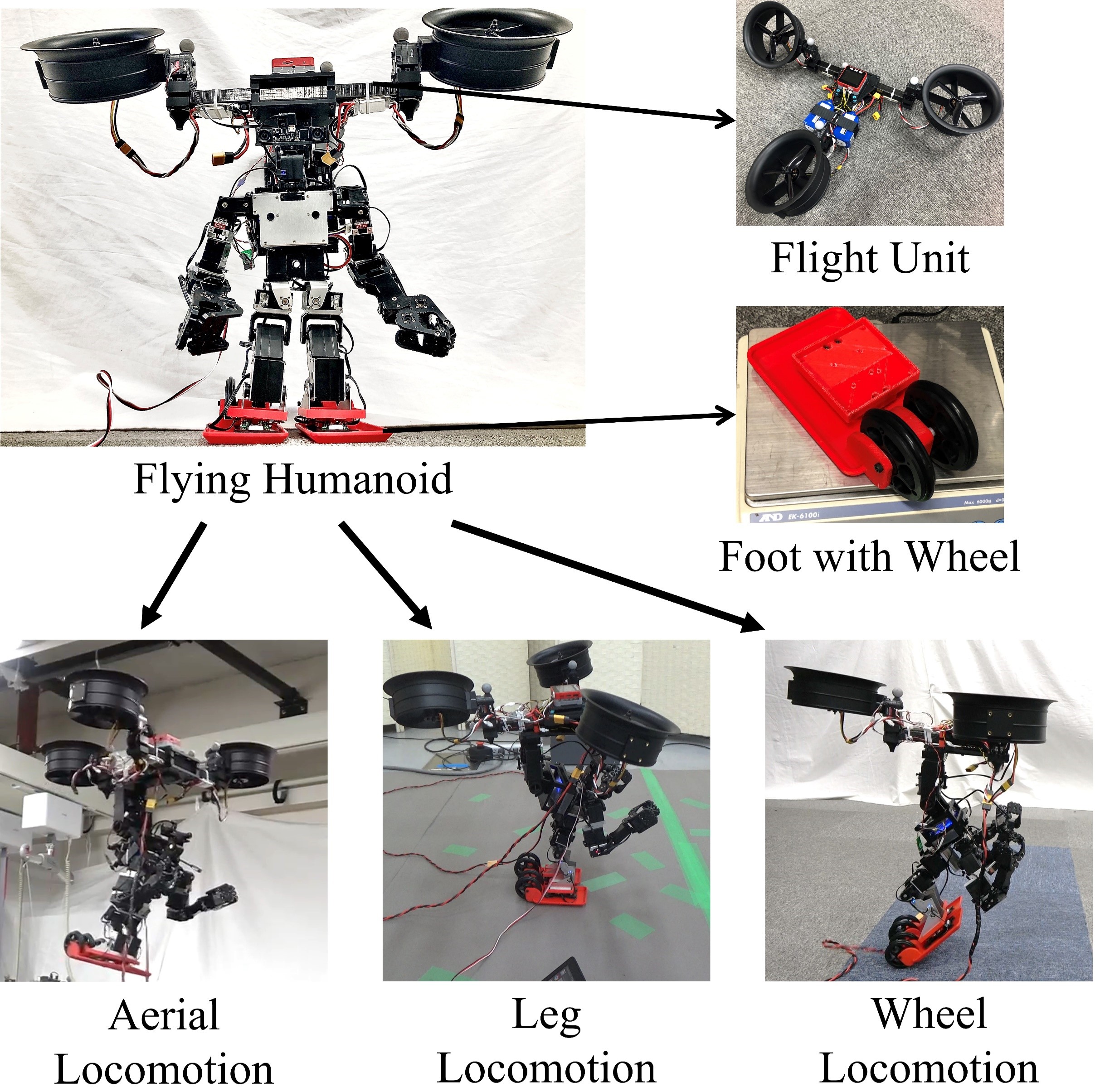
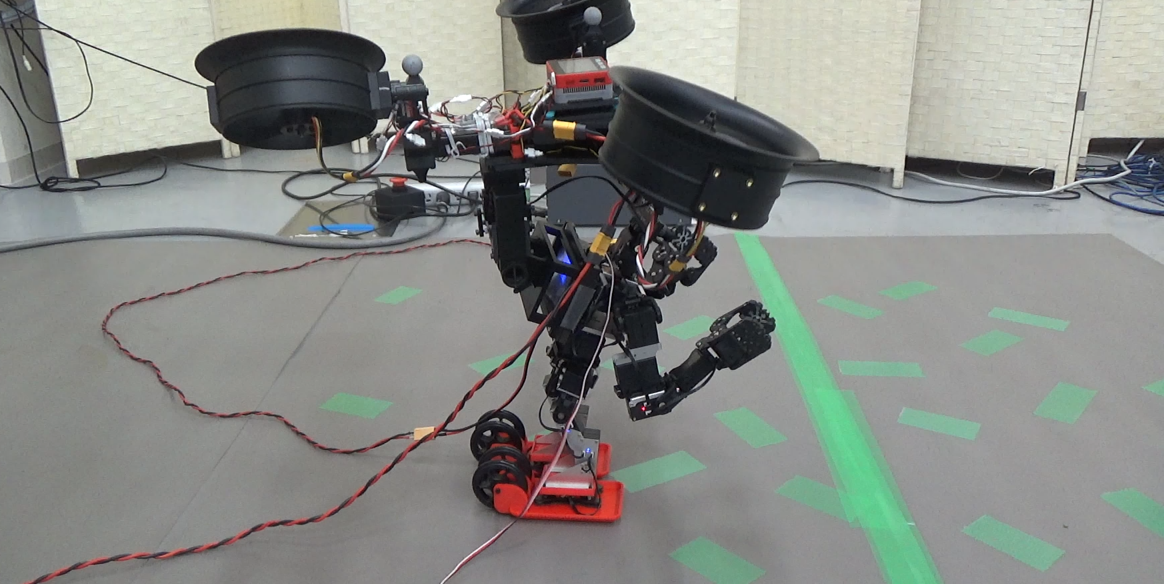
Humanoid robots are robot platforms that have multi-degree-of-freedom limbs, so they can perform many tasks just like humans. For this reason, many studies have been conducted on the use of humanoids in human living spaces [1] and disaster sites [2]. Particularly, various locomotion methods for humanoids have been developed [3][4][5]. On the other hand, the speed of bipedal walking is relatively slow. Bipedal locomotion has a small support area on the foot, and there is a risk of losing balance and falling when attempting to move at high speed. Another challenge in bipedal walking is the domain of locomotion is limited to the ground. In environments where there are barriers that cannot be overcome by the legs, locomotion becomes difficult. It is important to expand the domain where humanoids can move to do tasks in various environments. In particular, flying is effective for overcoming uneven or steep terrain. Therefore, in this work, we aim to achieve rapid terrestrial locomotion and aerial locomotion abilities by humanoids as shown in Fig. 1.
There are some humanoids with terrestrial locomotion methods rather than bipedal walking such as wheels [6] or crawlers [7]. Compared to walking by legs, these locomotion methods are based on wheel rotational motion, which makes it easier to achieve high-speed locomotion. In [8], wheels are deployed to a drone for terrestrial locomotion by aerial robots. Thrust can be applicable to stabilize the motion of humanoids as presented in [9] and enables aerial locomotion. Therefore, we propose a humanoid equipped with wheels and a flight unit to achieve rapid terrestrial and aerial locomotion. In [6] and [7], wheels and crawlers required additional actuators to drive them, however, increasing weight is disadvantageous when aerial locomotion. So, we propose passive wheels which enable a minimum increase in weight and utilize thrust for propulsion.
Some robots have legs and thrusters on their torso for aerial locomotion. In [10], a bipedal robot that combines a quadrotor was developed. This robot can move through multiple environments but does not have manipulators. Full-body flying humanoid platform with a birotor flight unit could walk and fly [11]. Birotor and quadrotor in these related works are under-actuated, which causes problems such as a lack of full pose trackability in aerial locomotion. Therefore, we deploy a flight unit with fully-actuated flight control to achieve full pose trackability of flying humanoid. By increasing the number of rotors, the number of control degrees of freedom can be increased. However, if the number of rotors is increased too much, the humanoid’s motion may become unstable due to a high center of gravity and it may cause aerodynamic interference from rotors on arms. Therefore, in this work, a thrust vectoring mechanism is used to realize fully-actuated flight control with three rotors. The thrust vectoring mechanism provides a degree of freedom to tilt the rotor. Using the thrust vectoring mechanism, the control degree of freedom is increased and it is used to achieve control redundancy [12] or exert forces to the environment [13]. This mechanism enables flying with less number of rotors such as birotor [14] or trirotor [15].
Humanoids with thrusters can use thrust not only for flying but also stabilization of motion. In [9], model-based thrust control was used for the assistance of motion to overcome barriers by a bipedal robot with thrusters. Reinforcement learning is used to calculate thrust output to stabilize walking motion against disturbance in [16]. Thrust is also used to reduce the load torque on the leg joints of a quadruped robot with thrusters [17]. In this work, an integrated control framework of flying humanoid for stabilization, maneuvering, and decrease of load torque on joints is proposed. This control framework can switch locomotion mode seamlessly.
The main contribution of this work is summarized as follows:
-
1.
We propose an optimized construction method of a humanoid robot equipped with wheels and a flight unit to achieve rapid terrestrial locomotion and aerial locomotion.
-
2.
We present an integrated control framework of flying humanoid including threes mode of locomotion: aerial locomotion, leg locomotion, and wheel locomotion.
-
3.
We achieve multimodal locomotion and aerial manipulation by the proposed flying humanoid robot.
The remainder of this paper is organized as follows: The design and modeling of the flying humanoid are introduced in Sec. II. Based on the optimization of orientation, the desired configuration of a flying humanoid is also presented in Sec. II. In Sec. III, an integrated control framework of the proposed flying humanoid is described. We then show the implemented flying humanoid and experimental results in Sec. IV. Finally, conclusions are presented in Sec. V.
II DESIGN AND MODELING
II-A Flight Unit
In this work, a fully-actuated trirotor was deployed on the humanoid. This flight unit contains three rotors and a degree of freedom to tilt each rotor. By properly arranging three rotors that can exert forces in two directions, it is possible to realize fully-actuated control that enables control position and attitude independently. This makes it possible to exert torque on the humanoid without exerting translational forces.
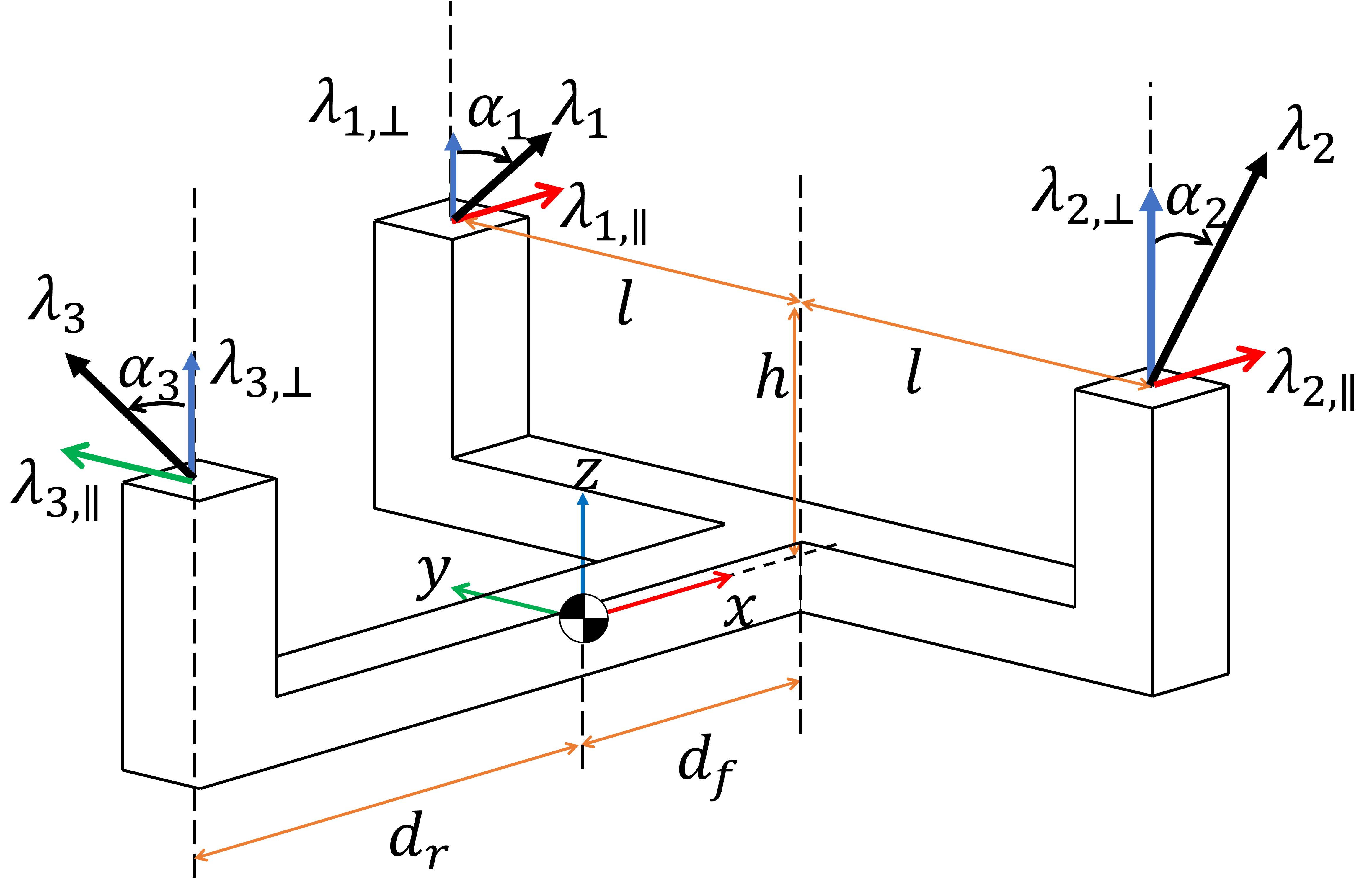
The dynamics model of the fully-actuated trirotor in this work is depicted in Fig. 2. From the Newton-Euler equations, translational and rotational motions are described as follows respectively
| (1) | ||||
| (2) |
where , , , , , , , are the mass of the robot, the position of the body in the world frame, the gravitational vector, the rotation matrix of the CoG frame w.r.t the world frame, inertia matrix of the body, the angular velocity of the body, force and torque generated by the thrusts. and are described in the CoG frame. From Fig. 2, the force and torque in the CoG frame can be described as follows
| (3) | ||||
| (4) |
where , , , are length of links described in Fig. 2. Each rotor has vectoring freedom so the thrust force can be divided into horizontal () and vertical () components.
is full rank and there exists an inverse matrix, the thrust vector is calculated as follows
| (5) |
Thrust and vectoring angle of each rotor can be calculated as follows
| (6) | ||||
| (7) |
II-B Flying Humanoid with Passive Wheel on Foot
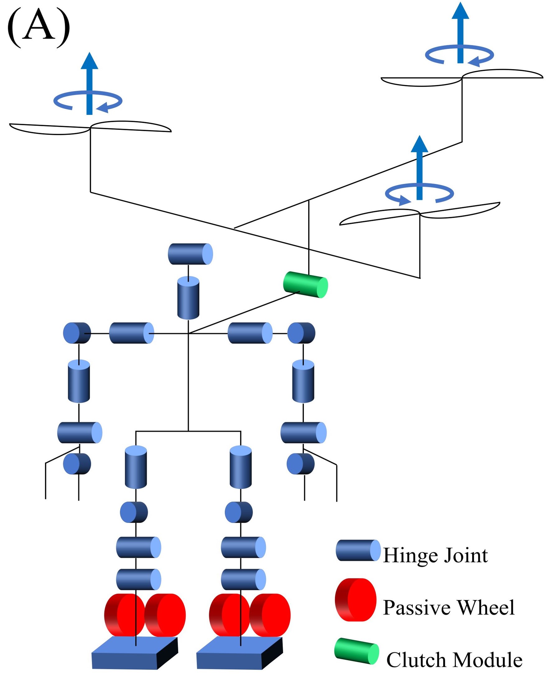
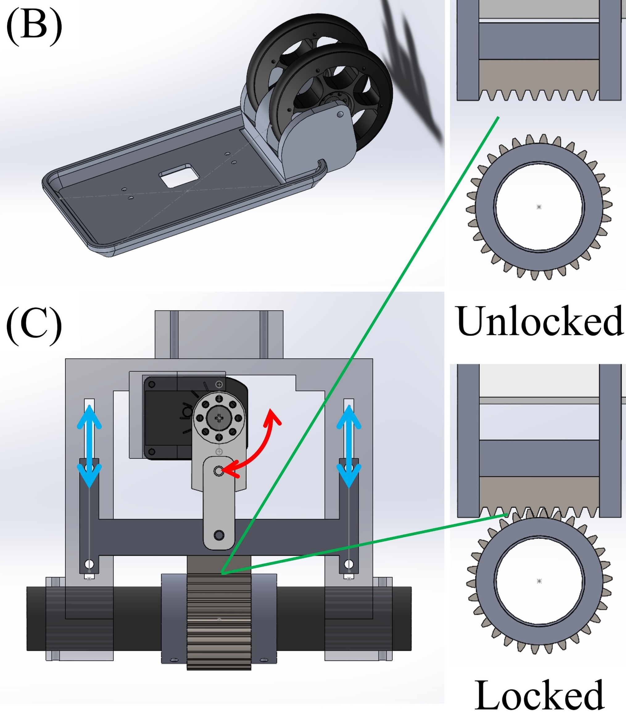
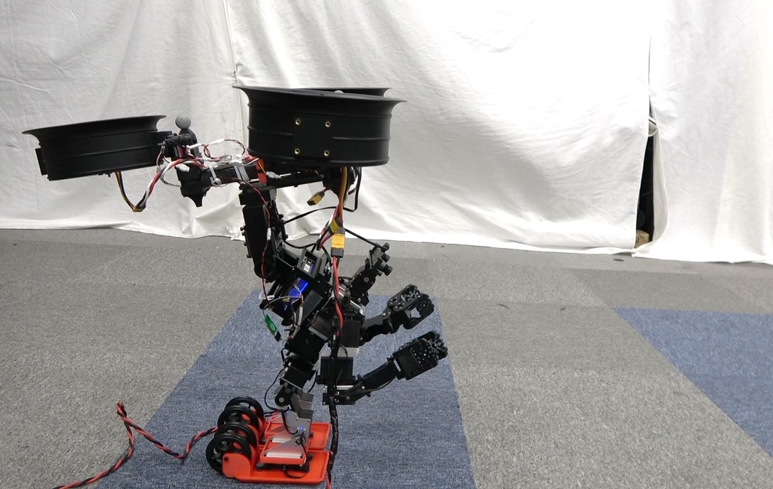
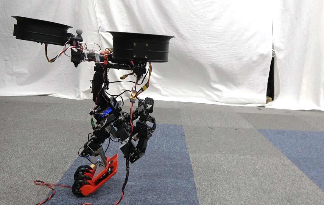
In this work, the humanoid is equipped with a flight unit to achieve terrestrial and aerial locomotion abilities. To avoid aerodynamic interference from rotors on the arms during aerial manipulation, the flight unit is deployed behind the arms. The joint configuration of the humanoid in this work is shown in Fig. 3 (A). Passive wheels are deployed on the foot as a way to realize rapid terrestrial locomotion than walking by legs. The passive wheels require minimal additional links and can be implemented without increasing the number of actuators, which is advantageous for aerial robots with payload constraints. The foot design is shown in Fig. 3 (B). Wheels are deployed on the heel to avoid interference with arms in manipulation tasks such as picking up an object on the ground. The distance between the foot plane and the radius of the wheels is the same, so the robot can switch states in which the foot plane is fully contacted and a state in which it is contacted only by the wheels by changing the other joints of the leg. When moving by wheels, maneuvering is achieved by thrust, enabling the robot to move faster than walking with less energy consumption than flying.
II-C Clutch Module
In the connection between a humanoid and a flight unit, the relative pitch angle can be considered as a parameter. In this work, we achieve a rotational degree of freedom around the pitch axis in a connection. In addition, the rotational degree of freedom should be fixed to stabilize the motion of humanoid and aerial locomotion. We designed a clutch module as shown in Fig. 3 (C) for connection. It can switch states in which it can rotate freely around a cylindrical axis and a state in which its rotation is fixed. A crank mechanism driven by a servo motor is used to switch the rotational degree of freedom by pressing a rack against a gear fixed around the rotational axis. No torque is generated around the rotational axis of the actuator to fix, so this mechanism is durable. This module is deployed on the back of the humanoid as shown in Fig. 3 (A). The relative pitch angle is determined in each mode of locomotion based on the optimization method in Sec. II-D to achieve a robust state.
II-D Optimal Orientation of Flight Unit
Using a clutch module described in Sec. II-C the relative angle in the connection between the humanoid and flight unit becomes reconfigurable. We reveal the optimal attitude of the body link of the trirotor in terms of the robustness of the control. In previous work, the arrangement of rotors was optimized to maximize feasible force and torque [18]. In this work, we only focus on pitch rotation and design an optimization problem that obtains the optimal pitch angle to maximize the range of the feasible torque because the structure is symmetrical around other axes. The optimization problem can be obtained as follows
| (8) | ||||
| subject to | (9) | |||
| (10) | ||||
| (11) | ||||
| (12) | ||||
| (13) | ||||
| (14) |
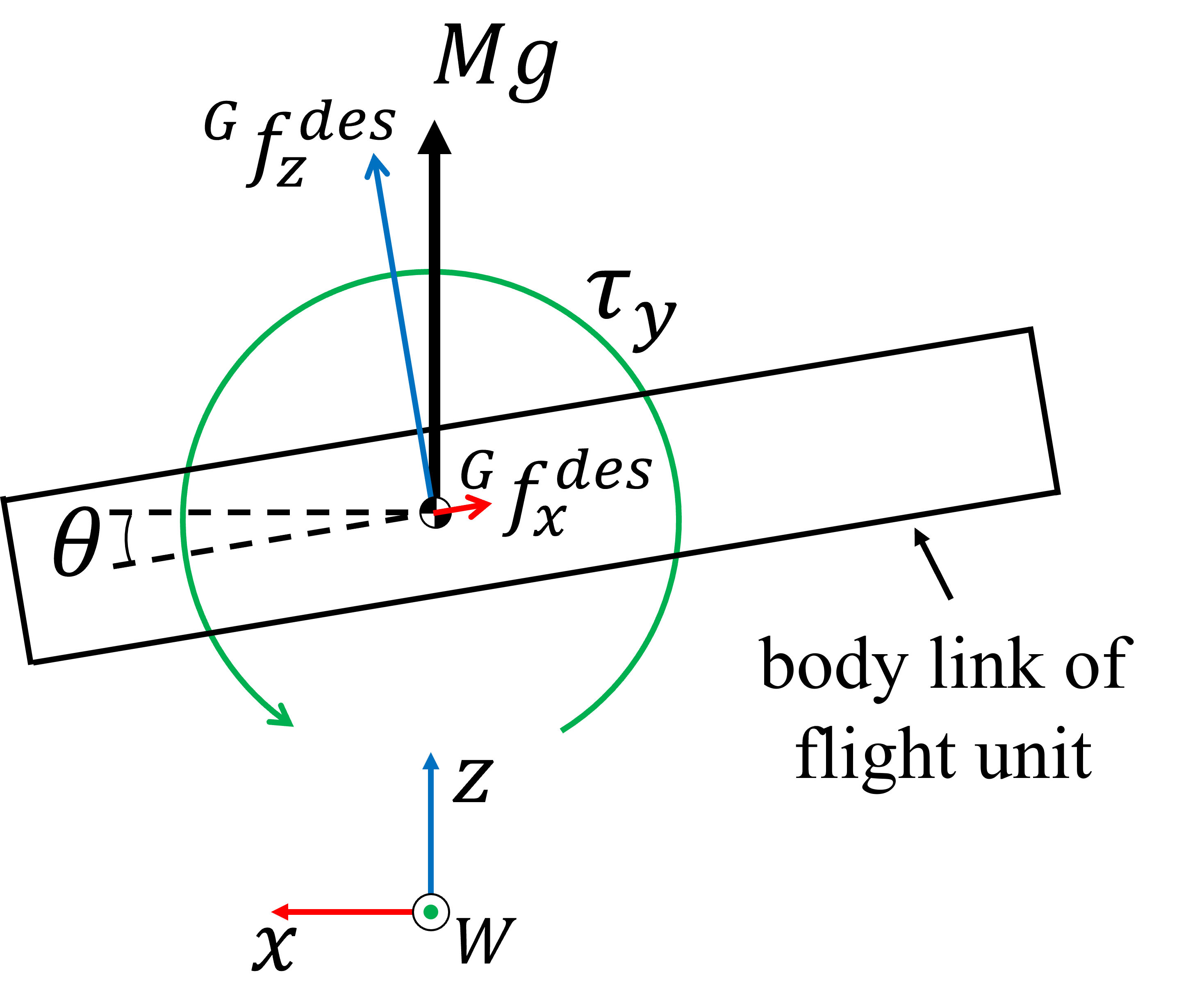
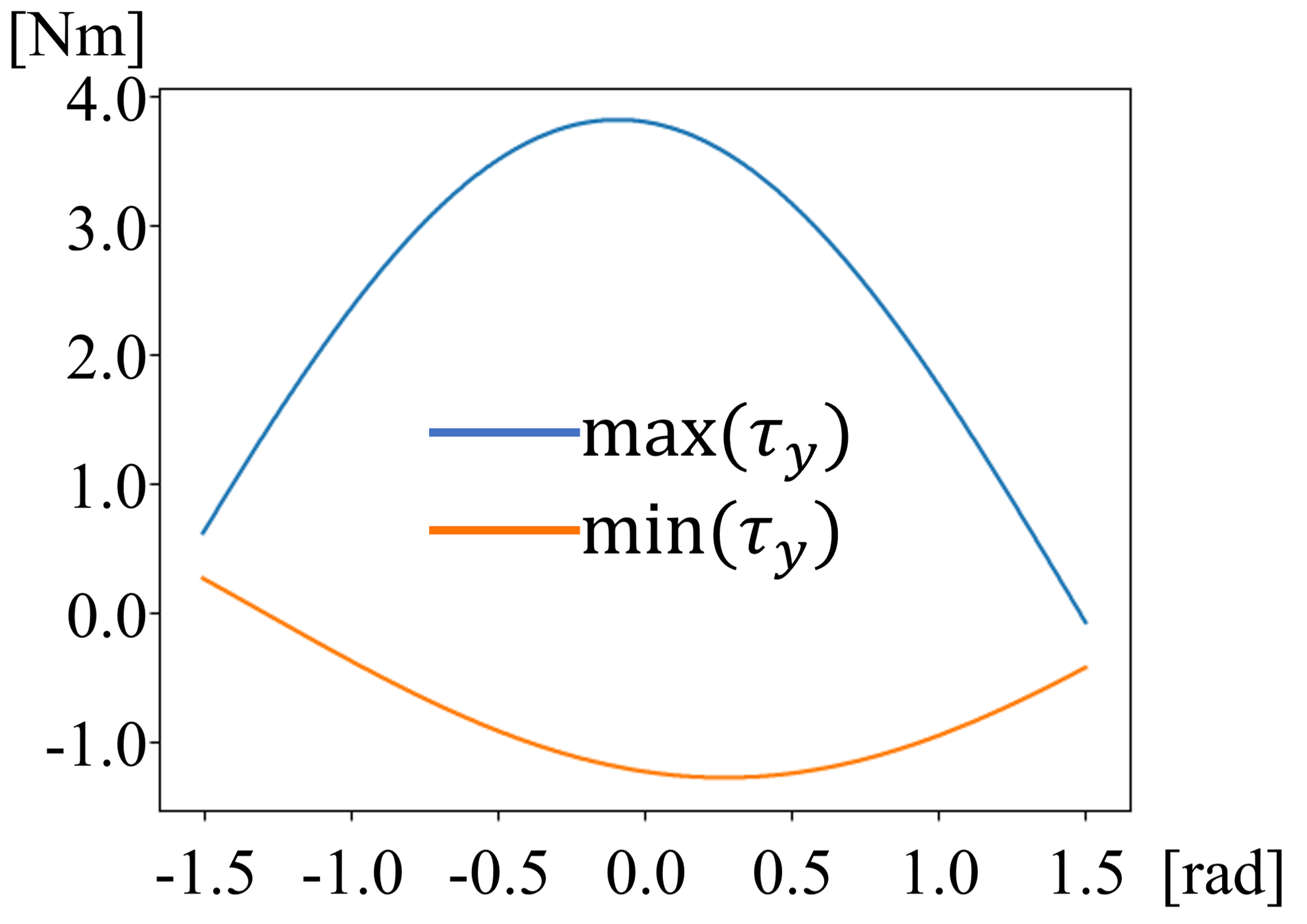
(10) means that when the flight unit is tilted by pitch angle, the force required for hovering is divided into x and z axis in the CoG frame as shown in Fig. 4. Besides, the target torque around pitch axis is . (13) and (14) are constraints on the upper and lower limits of the thrust and vectoring angle, setting thresholds that are feasible for real actuators. Feasible is calculated for each , and and in (8) are a maximum and a minimum value of them respectively, and they are shown in Fig. 5. that maximizes the range of feasible torque around the pitch axis is 0. In this state, the robustness is maximized.
II-E Desired Clutch Angle
In Sec. II-D, we reveal the optimal orientation of the flight unit. The joint angles of humanoid are changed depending on the mode of locomotion. It is needed to determine the appropriate clutch angle under each mode of locomotion based on the center of gravity and foot contact condition. In each mode of locomotion, that is the relative pitch angle between the humanoid and flight unit should be in the following set
| (15) |
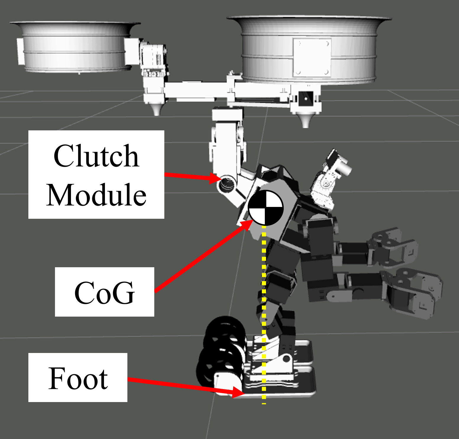
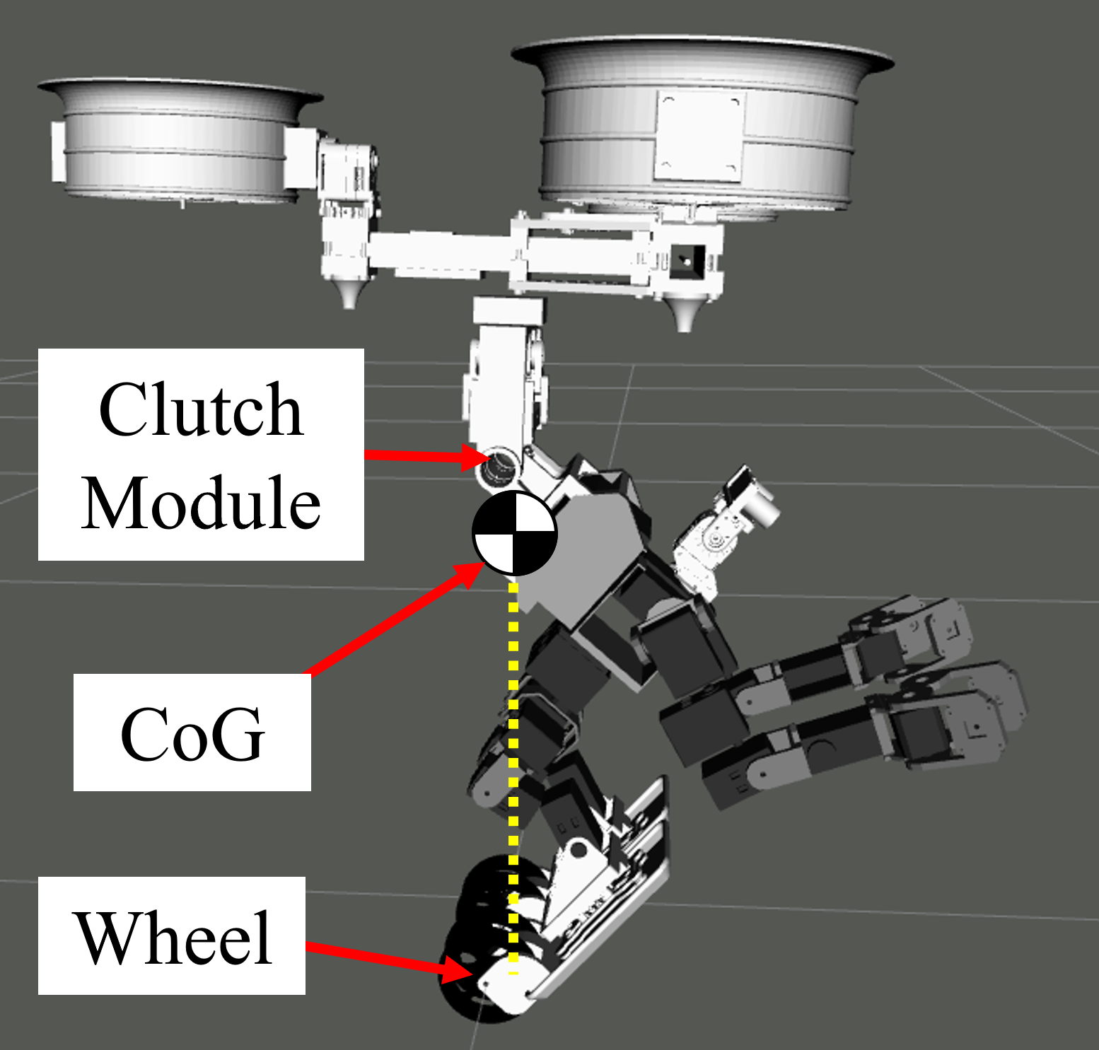
where , , , and is joint angle vector of the humanoid, optimal pitch angle of the flight unit described in Sec. II-D, pitch angle of torso link of humanoid, and orthographic projection of the center of gravity of humanoid to the ground, respectively. and are calculated by forward kinematics using a robot model and . means support polygon area of each mode of locomotion and described as follows. In leg locomotion mode, is a support rectangle of feet. In wheel locomotion mode, is a line segment connecting ground contact points. One of the valid poses in leg locomotion and wheel locomotion are depicted in Fig. 6 (A) and Fig. 6 (B). In aerial locomotion mode, the valid pose is the same as leg locomotion mode because the foot should be horizontal to the ground for stable takeoff and landing.
(A)
(B)
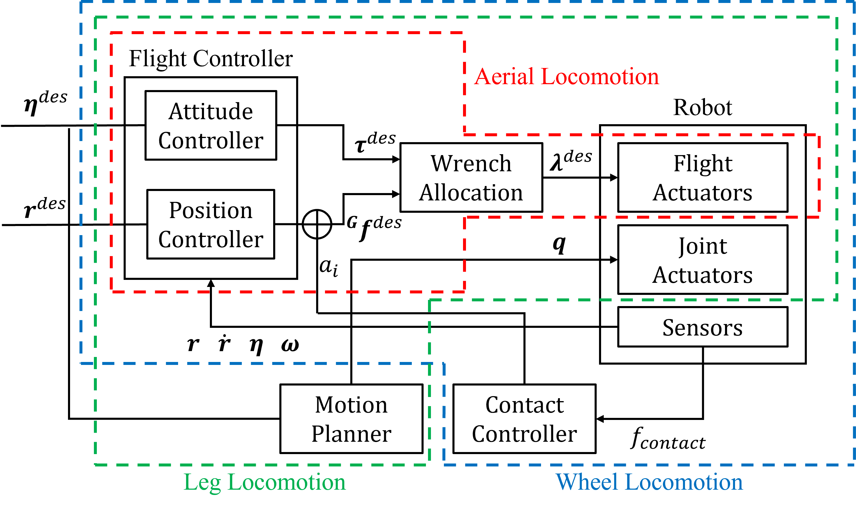
III CONTROL
In this section, an integrated control framework of a flying humanoid shown in Fig. 7 is described. Firstly, we present flight control that consists of attitude control, position control, and wrench allocation. Flight control is also used in leg locomotion and wheel locomotion. Then, the motion planning method for leg locomotion and the contact control method for wheel locomotion are described.
III-A Aerial Locomotion
Flight control consists of attitude control, position control, and wrench allocation.
III-A1 Attitude Control
The target torque in the CoG frame can be calculated as follows.
| (16) | ||||
| (17) |
where , are euler angle vector and PID gain diagonal matrices respectively.
III-A2 Position Control
The target translational force in the CoG frame can be calculated as follows
| (18) |
| (19) |
where are the PID gain diagonal matrices.
III-A3 Wrench Allocation
Target thrust and vectoring angle of each rotor is calculated from the target torque and translational force in the CoG frame using (3)-(7).
III-B Leg Locomotion
In this work, we used thrust exerted by flight control to stabilize the walking motion. In each footstep motion during walking, desired roll and yaw angle of flight control is updated as follows
| (20) | ||||
| (21) |
and are the roll and yaw angles of the torso link of humanoid when support leg is parallel to the ground. They are calculated by forward kinematics using a robot model and joint angle vector . Besides, the target x-y position is updated to the position at the time. The target position of z is set above the position of the flight unit to avoid falling. And, linear acceleration in z-direction should be larger than to decrease load torque on leg joints and raise the swing leg stably. In addition to this constraint, thrust should be small enough not to hover, so the following clamp is added in the position control
| (22) |
III-C Wheel Locomotion
In wheel locomotion mode, foot and ground make point contact and maneuvering is more difficult than leg locomotion. We introduce feedback control to maintain stable contact with the ground while wheel locomotion. Contact force with the ground is measured by force sensors installed on the foot. A feedback term is introduced in position control of z. The position control while wheel locomotion is described as follows
| (23) |
where are PID control gains. is updated in the control loop as follows
| (24) |
where , , and are feedback gain, contact force, and target contact force, respectively.
In addition to this feedback term, the following clamp is added because it is necessary to exert the minimum thrust to prevent falling and hovering just like (22)
| (25) |
where is minimum linear acceleration to avoid falling.
IV EXPERIMENT
In this section, we present a flying humanoid robot implemented in this work. Then, we conduct locomotion experiments in each mode: aerial, legged, and wheeled locomotion. Finally, an aerial manipulation experiment is conducted.
IV-A Robot Platform
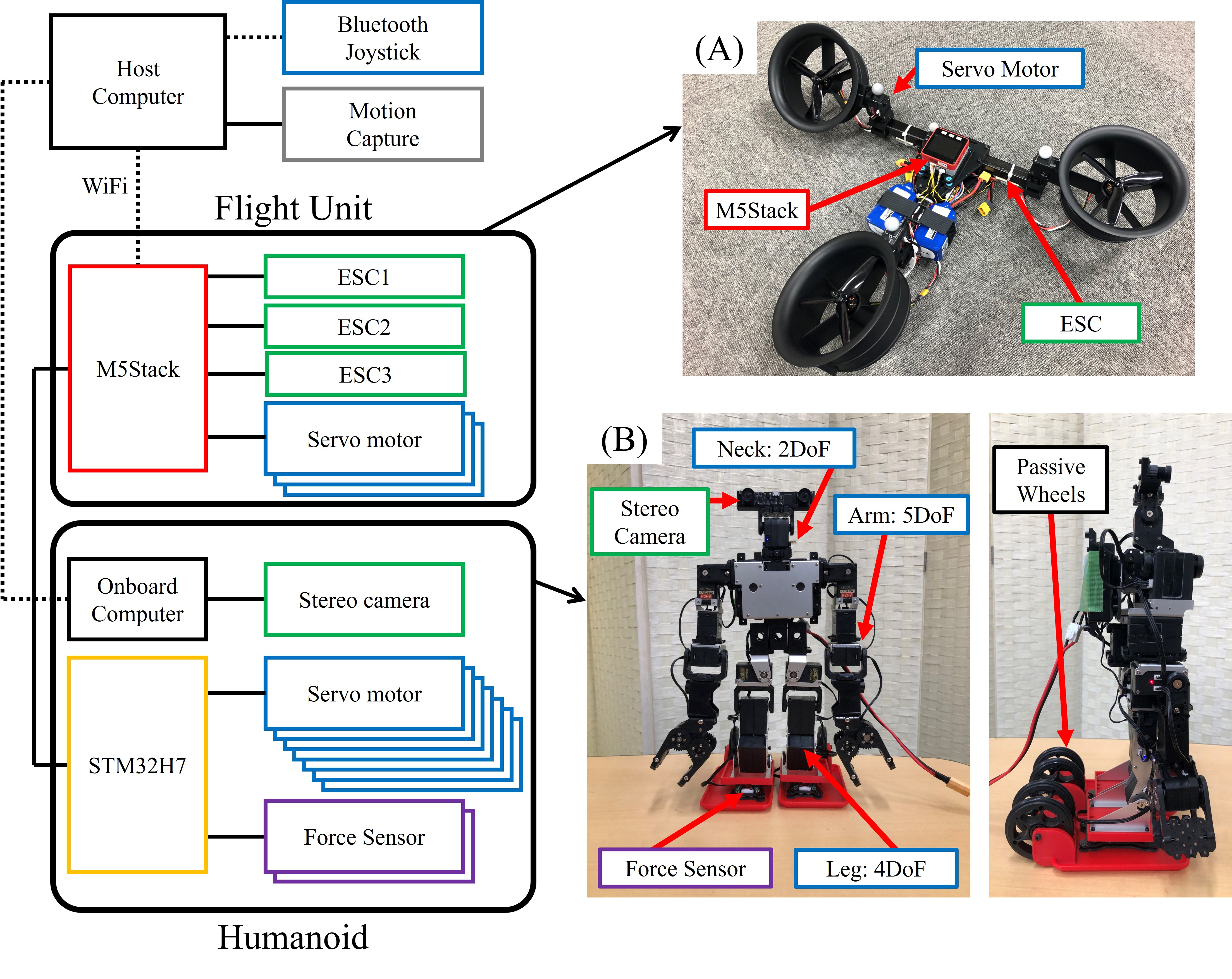
The total hardware system is shown in Fig. 8. Flying humanoid consists of a fully-actuated trirotor flight unit (Fig. 8 (A)) and a humanoid robot KHR-W (Fig. 8 (B)).
IV-A1 Flight Unit
The fully-actuated trirotor flight unit has three EDFs (Electric Ducted Fan), and three ESCs (Electric Speed Controller). In this work, we developed a trirotor flight unit as shown in Fig. 8 (A), and the specifications are described in Table I. The maximum thrust of the EDF is 18N. Servo motors for vectoring control of rotors were KRS-3304R2 ICS. The body of the trirotor is made of CFRP square pipe for a lightweight design. The rest of the body is made of PLA. M5Stack with an ESP32 microcontroller (2 cores, 240 ) was deployed to perform the realtime pose control (100 ) as presented in Fig. 7. IMU (Inertia Measurement Unit) in M5Stack and external motion capture system (sampling rate: 100 ) were used to estimate the state of the body.
| Attribute | Value |
|---|---|
| rotor KV | |
| max rotor thrust | |
| max vectoring torque | |
| vectoring angle range | [-3/4, 3/4] |
| mass | |
| power | |
| size |
| Attribute | Value |
|---|---|
| leg joint max torque | |
| arm joint max torque | |
| power | |
| mass | |
| size |
IV-A2 Humanoid KHR-W
In this work, we developed a humanoid robot KHR-W as shown in Fig. 8 (B). Table II shows the specifications of KHR-W. This is made from KHR that is a hobby robot product by Kondo Kagaku Co. Ltd. KRS-2552R2HV ICS is used for 2 DoF neck and 5 DoF arms, and KRS-2572R2HV ICS is used for 4 DoF legs. It also has two passive wheels in each foot as shown in Fig. 3. Force sensors proposed in [19] are deployed on the foot for feedback control described in Sec. III-C. For control of joint servo motors and force sensors, the MCU board with STM32H7 (1 core, 480 ) is in the back of the body. A stereo camera module on the head and UPBoard with Intel Atom x5-Z8350 processor (4 cores, 1.92 ) at the back of the body are deployed to get an image of view and process it.
(1)
(2)
(3)

IV-B Locomotion Experiment
IV-B1 Aerial Locomotion
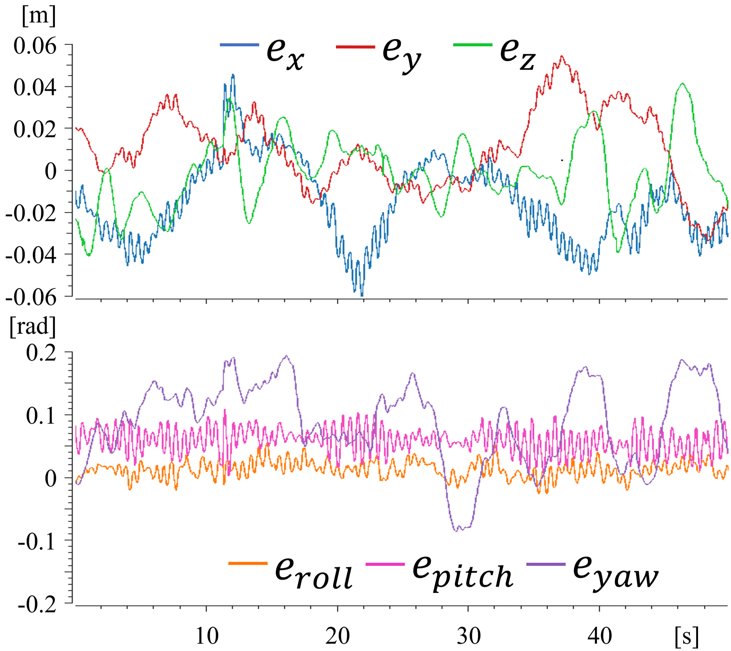
A hovering experiment was conducted to evaluate the stability of aerial locomotion. that is the relative pitch angle between the humanoid and flight unit described in Sec. II-E was 25 deg in this experiment. Fig. 9 shows position and attitude errors during hovering. RMS of those errors were and . The maximum absolute values of these errors were and .
(1)
(2)
(3)
IV-B2 Leg locomotion using thrust
We conducted walking experiments, using thrust control described in Sec. III-B and not using thrust. The relative pitch angle between the humanoid and flight unit was the same as in the aerial locomotion experiment. When without thrust control, a walking motion was not stable and fell down. As Fig. 10 show, walking without falling was achieved by using thrust to stabilize motion. For a body weight of 3.5kg, the sum of thrust exerted by rotors was about 15N. As described in Sec. III-B target position is updated with the current position. Generally, if the target position is updated in such a way, target linear acceleration becomes constant and translational motion will be uniformly accelerated. However, in this walking experiment, the foot can receive friction from the ground, and walking motion is achieved. Fig. 11 is a plot of position and attitude. Target roll and yaw angle are updated based on a robot model and actual attitude follows it. Walking velocity was 0.003 m/s which is relatively slow. This is because tracking of attitude control needs to be slow for stable motion.
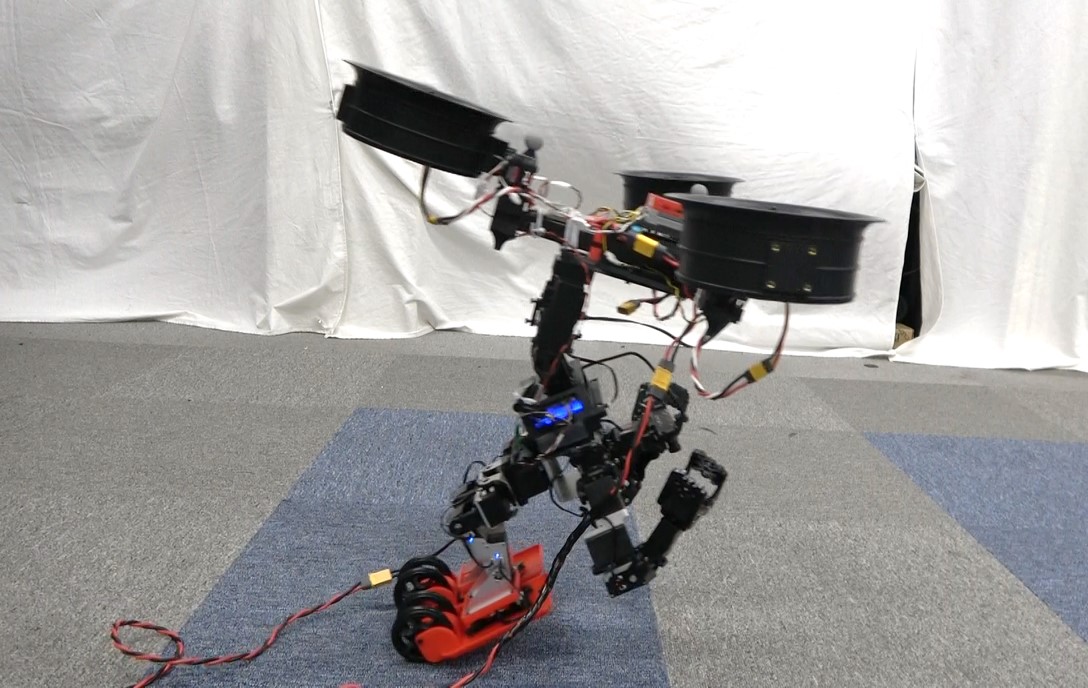
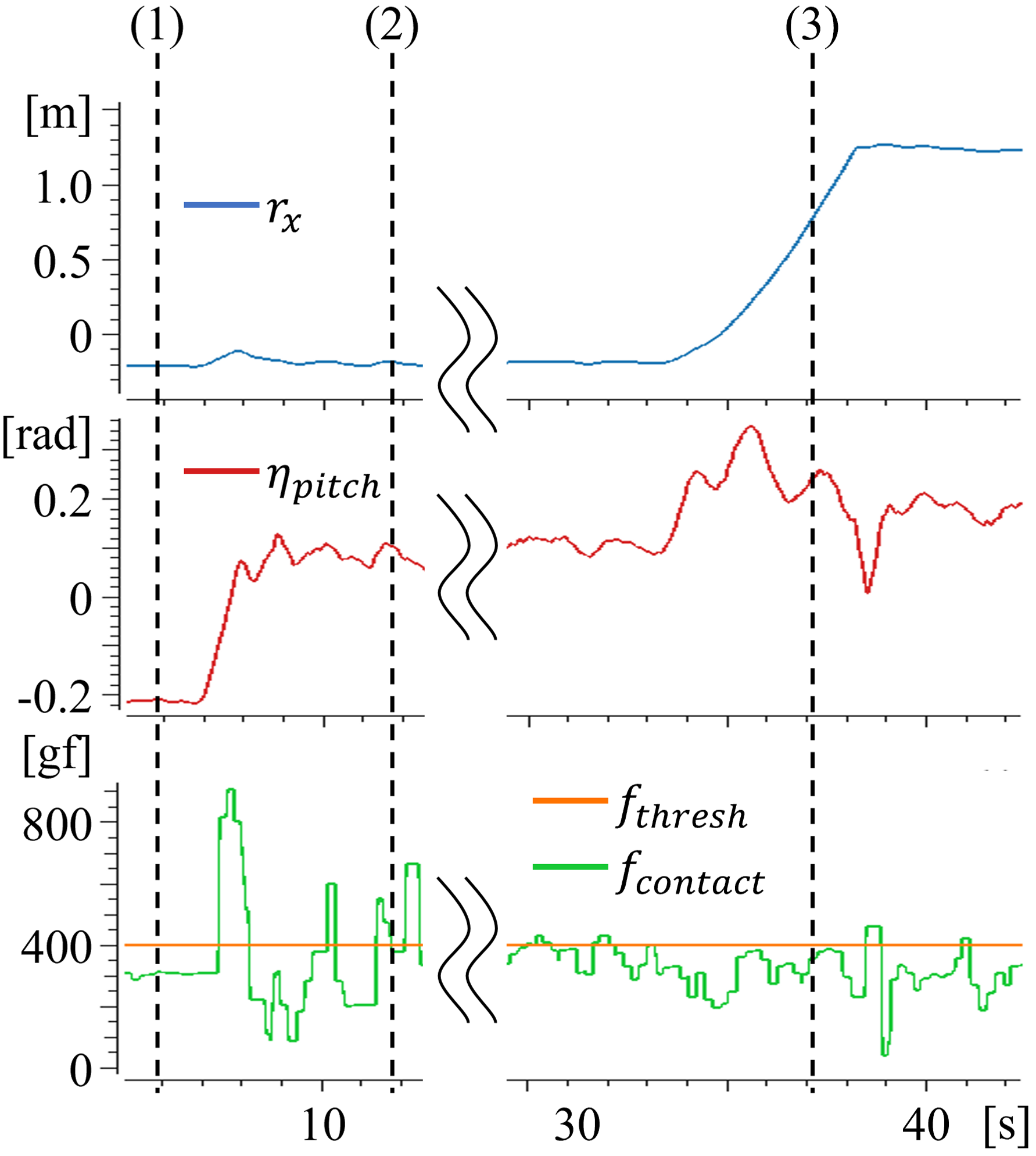
IV-B3 Wheel locomotion
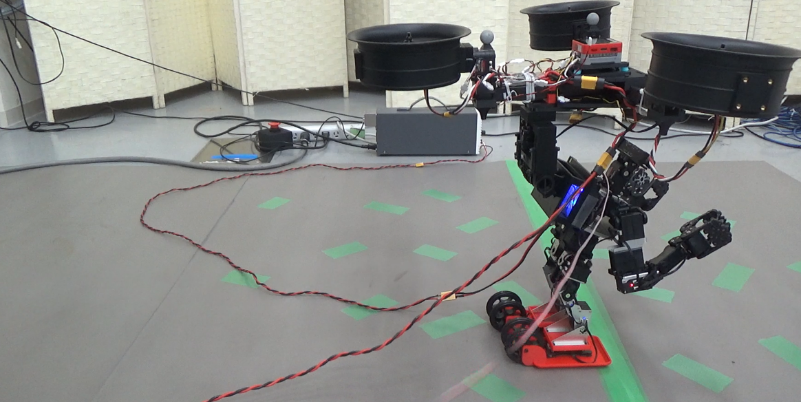
To evaluate the feasibility of multimodal locomotion on the ground, an experiment including transformation and wheel locomotion was conducted. Initially, the feet are completely contacted with the ground. Then start thrust control and drive the leg joint to stand by only wheels. At the beginning of the transformation, force feedback control described in Sec. III-C is started. In this experiment, the relative pitch angle between the humanoid and flight unit was 35 deg.
Fig. 13 shows the position of the trirotor and values on force sensors. In this work, we used a fully-actuated trirotor that can control position and attitude independently, however, during wheel locomotion, wheels receive reaction force from the ground, and flight unit moves forward, and the pitch angle of the body increased. Maximum pitch angle during moving forward was about 0.3. Maximum velocity of wheel locomotion was 0.4m/s and the sum of thrust exerted by rotors was about 28.
Wheel locomotion was faster than leg locomotion, however, the amount of thrust exerted by rotors was larger.
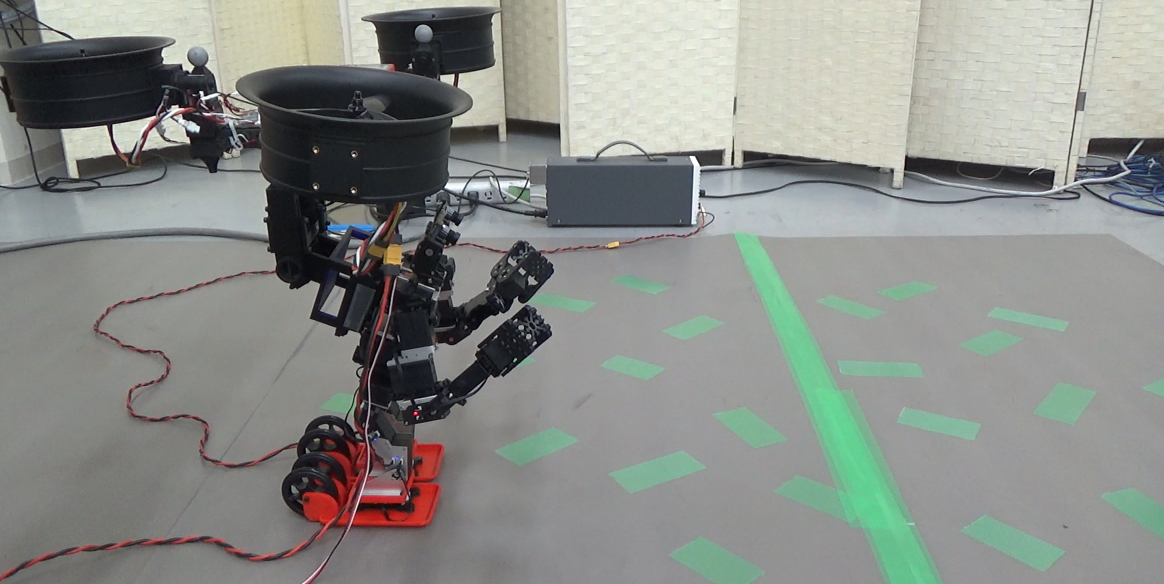
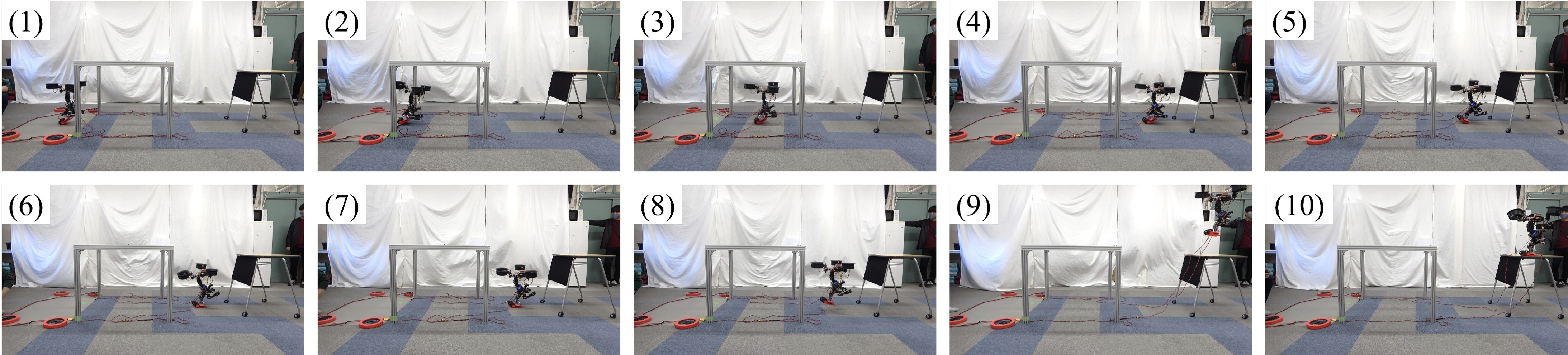
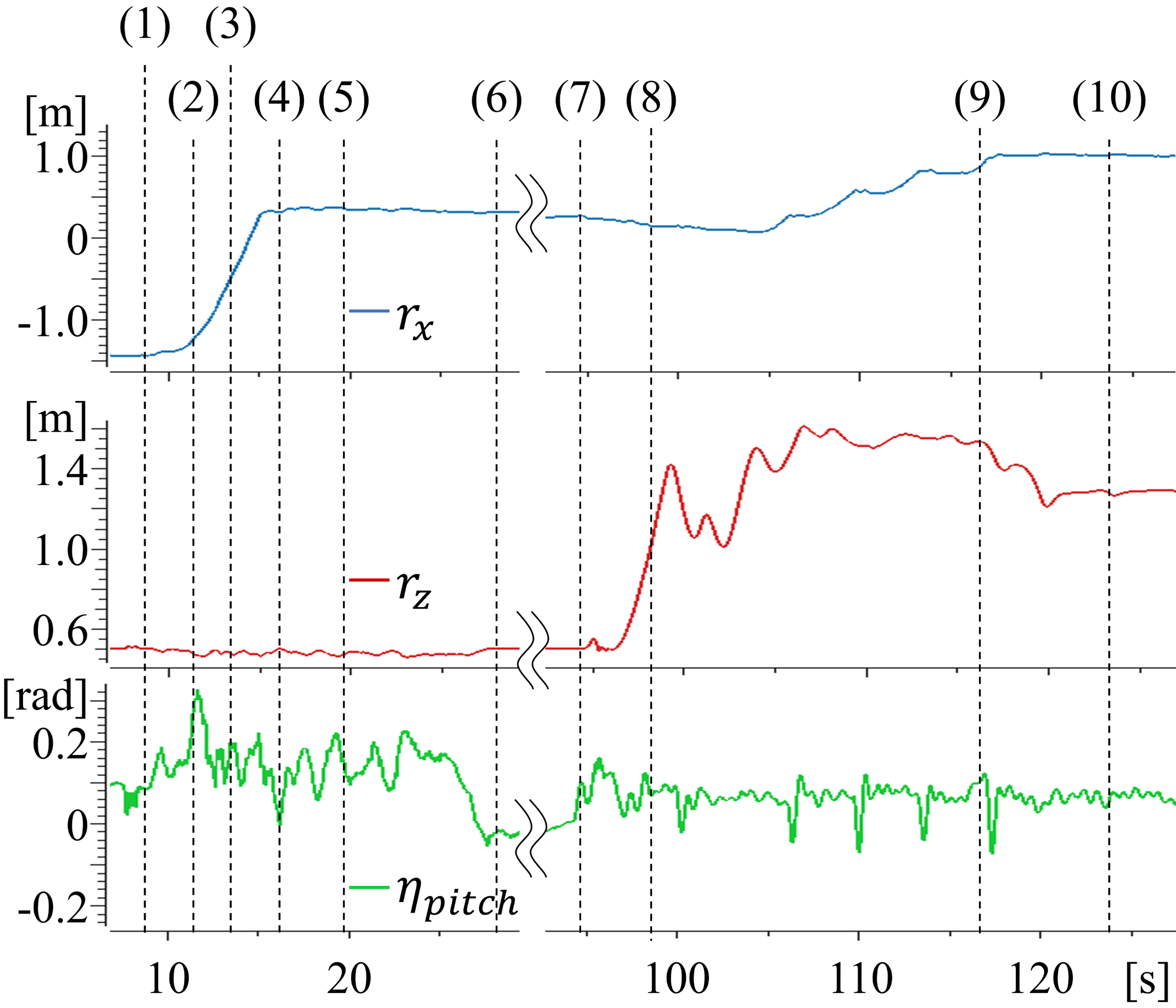
IV-C Mutimodal Locomotion Experiment
We conducted a multimodal locomotion experiment with this robot as shown in Fig. 14. In a planer terrain with a limitation of vertical clearance where flight is impossible, it runs by wheels. Then, it flies and lands on the scaffold in a high place. Fig. 15 is plots of the position and pitch angle of the body during this experiment. In this experiment, a transition from wheel locomotion and aerial locomotion was seamlessly performed and locomotion in multiple domains was achieved.
IV-D Aerial Manipulation Experiment
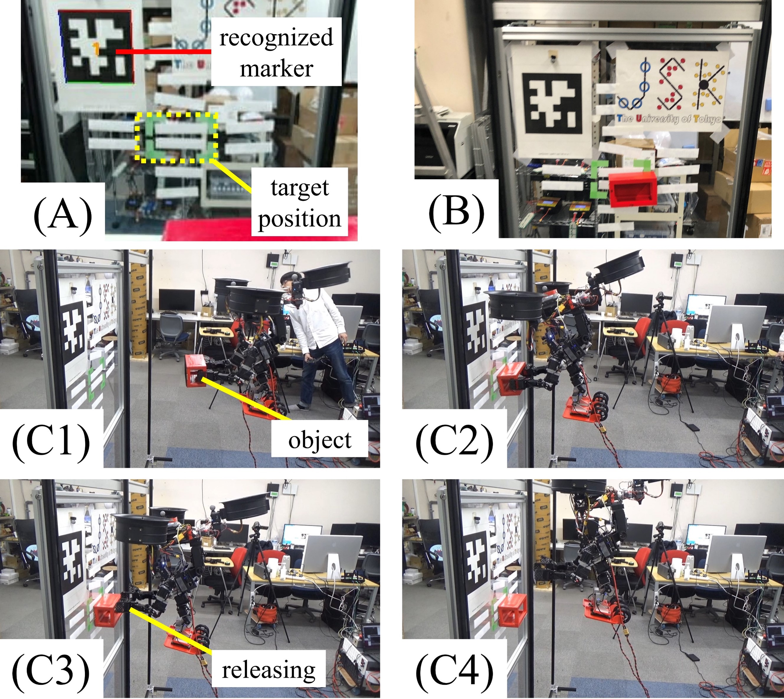
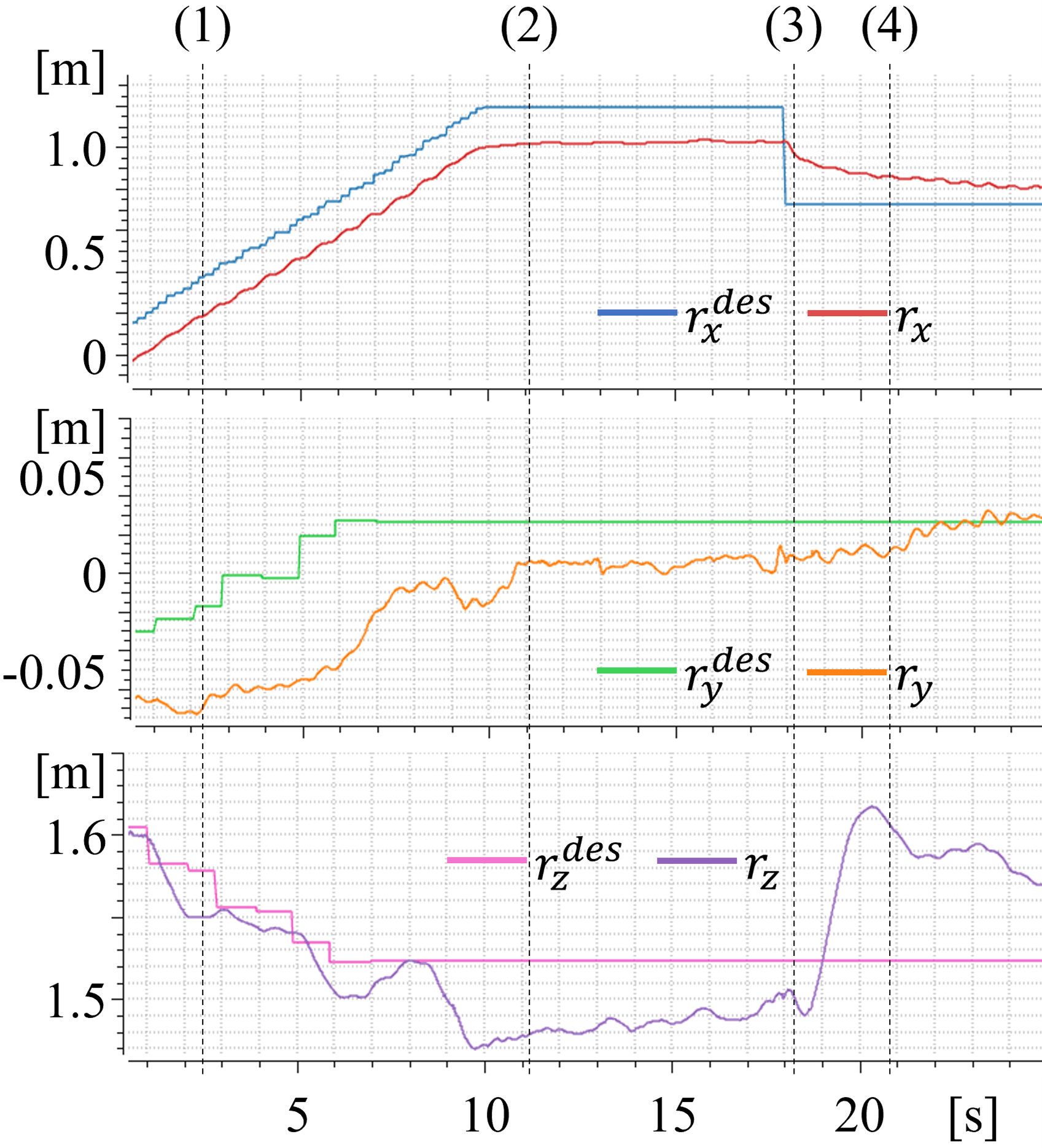
We conduct an aerial manipulation experiment using the proposed robot platform in Fig. 16 (C1)-(C4). A stereo camera module mounted on the head of KHR-W was used to capture the marker and set target position. An object grasped by arms is attached to a target position on a wall surface by pushing it. By observing a change of position, detect contact with the environment. After contacting for 3 seconds, release the object and leave from the wall.
Fig. 16 (A) and Fig. 16 (B) show the experimental environment and recognition result of the marker, a result of the experiment, respectively. Fig. 17 shows position data in this experiment. The errors of the attached position and target position are smaller than 0.1. As these results show, image recognition and manipulation abilities of humanoid could work in the air.
V CONCLUSIONS AND FUTURE WORK
In this work, we proposed a humanoid robot equipped with wheels and a flight unit to achieve rapid terrestrial locomotion and aerial locomotion abilities on humanoid. We developed a clutch module used for connection between the flight unit and humanoid to enable optimal configuration for multiple modes of locomotion. An integrated control framework for aerial, legged, and wheeled locomotion is proposed. Then, we construct a flying humanoid robot and conducted some experiments to evaluate our proposal. In locomotion experiments, aerial locomotion, leg locomotion, and wheel locomotion were archived. We also conduct a multimodal locomotion experiment which demonstrated the versatility of our proposed platform. Through an aerial manipulation experiment, recognition and manipulation abilities of humanoid were shown to be applicable in the air.
In future work, it is necessary to determine a suitable locomotion mode by a robot. By recognizing obstacles or walls using the field of image, it will be possible to determine the appropriate locomotion mode. Besides, the manipulation experiment in this work was a simple task. This robot can use its legs as end effectors in the air so transporting larger objects in multiple domains will be possible.
References
- [1] Kenji Kaneko, et al. Humanoid robot hrp-2. Proceedings - IEEE International Conference on Robotics and Automation, Vol. 2004, pp. 1083–1090, 2004.
- [2] Kunio Kojima, et al. Development of life-sized high-power humanoid robot JAXON for real-world use. In Proceedings of the 2015 IEEE-RAS International Conference on Humanoid Robots (Humanoids 2015), pp. 838–843, November 2015.
- [3] Yuta Kojio, et al. Unified balance control for biped robots including modification of footsteps with angular momentum and falling detection based on capturability. In Proceedings of The 2019 IEEE/RSJ International Conference on Intelligent Robots and Systems, pp. 497–504, nov 2019.
- [4] Shuuji Kajita, et al. Biped walking pattern generation by using preview control of zero-moment point. Proceedings - IEEE International Conference on Robotics and Automation, Vol. 2, pp. 1620–1626, 2003.
- [5] Shuuji Kajita, et al. Biped walking stabilization based on linear inverted pendulum tracking. IEEE/RSJ 2010 International Conference on Intelligent Robots and Systems, IROS 2010 - Conference Proceedings, pp. 4489–4496, 2010.
- [6] Taejin Jung, et al. Development of the humanoid disaster response platform drc-hubo+. IEEE Transactions on Robotics, Vol. 34, pp. 1–17, 2 2018.
- [7] G. Clark Haynes, et al. Developing a robust disaster response robot. Journal of Field Robotics, Vol. 34, pp. 281–304, 3 2017.
- [8] Jared R. Page, et al. The quadroller: Modeling of a uav/ugv hybrid quadrotor. pp. 4834–4841. Institute of Electrical and Electronics Engineers Inc., 10 2014.
- [9] Zhifeng Huang, et al. Jet-hr1: Two-dimensional bipedal robot step over large obstacle based on a ducted-fan propulsion system. In 2017 IEEE-RAS 17th International Conference on Humanoid Robotics (Humanoids), pp. 406–411. IEEE, 2017.
- [10] Kyunam Kim, et al. A bipedal walking robot that can fly, slackline, and skateboard. Science Robotics, Vol. 6, No. 59, p. eabf8136, 2021.
- [11] Tomoki Anzai, et al. Design and development of a flying humanoid robot platform with bi-copter flight unit. In 2020 IEEE-RAS 20th International Conference on Humanoid Robots (Humanoids), pp. 69–75. IEEE, 2021.
- [12] M. Zhao, et al. Design, modeling, and control of an aerial robot dragon: A dual-rotor-embedded multilink robot with the ability of multi-degree-of-freedom aerial transformation. IEEE Robotics and Automation Letters, Vol. 3, No. 2, pp. 1176–1183, April 2018.
- [13] Nobuki Sugito, et al. Aerial manipulation using contact with the environment by thrust vectorable multilinked aerial robot. In Proceedings of The 2022 IEEE International Conference on Robotics and Automation, pp. 54–60, May 2022.
- [14] Youming Qin, et al. Gemini: A compact yet efficient bi-copter uav for indoor applications. IEEE Robotics and Automation Letters, Vol. 5, pp. 3213–3220, 4 2020.
- [15] Junyan Hu, et al. An innovative tri-rotor drone and associated distributed aerial drone swarm control. Robotics and Autonomous Systems, Vol. 103, pp. 162–174, 5 2018.
- [16] Fan Shi, et al. Learning agile hybrid whole-body motor skills for thruster-aided humanoid robots. IEEE International Conference on Intelligent Robots and Systems, Vol. 2022-October, pp. 12986–12993, 2022.
- [17] Moju Zhao, et al. Design, modeling and control of a quadruped robot spidar: Spherically vectorable and distributed rotors assisted air-ground amphibious quadruped robot, 2023.
- [18] Sangyul Park, et al. Odar: Aerial manipulation platform enabling omnidirectional wrench generation. IEEE/ASME Transactions on Mechatronics, Vol. 23, pp. 1907–1918, 8 2018.
- [19] Tasuku Makabe, et al. Design and development for humanoid-vehicle transformer platform with plastic resin structure and distributed redundant sensors. In Proceedings of The 2022 IEEE International Conference on Robotics and Automation, pp. 8526–8532, May 2022.