Dynamics of active defects on the anisotropic surface of an ellipsoidal droplet
Abstract
Cells are fundamental building blocks of living organisms displaying an array of shapes, morphologies, and textures that encode specific functions and physical behaviors. Elucidating the rules of this code remains a challenge. In this work, we create biomimetic structural building blocks by coating ellipsoidal droplets of a smectic liquid crystal with a protein-based active cytoskeletal gel, thus obtaining core-shell structures. By exploiting the patterned texture and anisotropic shape of the smectic core, we were able to mold the complex nematodynamics of the interfacial active material and identify new time-dependent states where topological defects periodically oscillate between rotational and translational regimes. Our nemato-hydrodynamic simulations of active nematics demonstrate that, beyond topology and activity, the dynamics of the active material are profoundly influenced by the local curvature and smectic texture of the droplet, as well as by external hydrodynamic forces. These results illustrate how the incorporation of these constraints into active nematic shells orchestrates remarkable spatio-temporal motifs, offering critical new insights into biological processes and providing compelling prospects for designing bio-inspired micro-machines.
Active nematics (ANs), composed of elongated self-propelled units, have emerged as a paradigm to understand a range of biological processes, from the reorganization of active fibers during morphogenesis to the collective dynamics of bacterial populations and tissue growth marchetti2013 ; needleman2017 ; doostmohammadi2018 ; zhang2021auto . By studying these systems under the umbrella of ANs, it becomes possible to exploit the theoretical framework that has been developed for equilibrium liquid crystals over the course of several decades to the profit of biology.
In particular, nematic defects, singular points where the orientational order is disrupted, have been found to play a key role in the regulation of cellular function at both single-cell and multicellular levels maroudas2021 ; meacock2021 ; copenhagen2021 ; fardin2021 . However, the mechanism by which topological defects interact with their environment to produce functional outcomes remains an open question. In vitro ANs provide a model platform to investigate this. Frictional forces thampi2014 ; doostmohammadi2016 ; thijssen2021 ; mozaffari2021 ; martinez-pratScalingRegimesActive2021a , surface viscous anisotropy guillamat2016 ; guillamat2017 ; thijssenActiveNematicsAnisotropic2020 , spatial patterning of active stresses zhang2021spatio ; tang2021 ; mozaffari2021 ; zhang2022logic , or confinement wioland2013 ; ravnik2013 ; keber2014 ; zhang2016 ; khoromskaia2017 ; wu2017 ; ellis2018 ; guillamat2018 ; sokolov2019 ; pearce2019 ; opathalage2019 ; hardouin2020 ; rajabi2021 have recently been used to program defect motion and induce organized flows in the material, offering new fundamental insights and interesting perspectives for the design of bio-inspired micro-machines. However, the effect of substrate curvature, crucial in cellular processes, has been little explored experimentally, due to the challenges in producing controlled curved environments to probe ANs.
In a pioneering study, Keber et al. keber2014 studied for the first time the effect of imposing a constant Gaussian curvature to a microtubule-kinesin AN, in which bundles of motor-propelled cytoskeletal filaments slide relative to each other, thereby producing a two-dimensional nematic field. In this material, a large number of topological defects randomly nucleate and annihilate, typically inducing a chaotic dynamics. By confining the AN to the surface of a spherical vesicle, they were able to stabilize a regular dynamic state characterized by the motion of four topologically required defects lubensky1992 ; lopez2011 . These experimental results have been replicated using various theoretical and numerical approaches zhang2020dynamics ; brownTheoreticalPhaseDiagram2020 . Moreover, high activity conditions are predicted to lead to the emergence of novel structures, such as vortices sknepnek2015 ; khoromskaia2017 ; janssen2017 ; zhang2016 and stable rotating-bands sknepnek2015 ; henkes2018 ; castro2018 .
Imposing a gradient of Gaussian curvature is expected to induce spatio-temporal patterns of greater complexityalaimo2017 ; ehrig2017 ; pearce2019 . In curved geometries with non-uniform Gaussian curvature, such as an ellipsoidal or toroidal surface, curvature gradients act as external fields inducing defect attraction towards regions of like-sign Gaussian curvature or even defect unbinding under certain conditions bowick2009 ; bates2010 ; kralj2011 ; de2016 ; jesenek2015 . Such phenomena can dramatically influence the dynamics of the active system. For instance, when confining the AN to the surface of a prolate ellipsoid, curvature gradients are expected to trigger the segregation of defects to the poles bates2010 ; kralj2011 and the formation of tunable rotating states alaimo2017 . Although the interplay between non-uniform Gaussian curvature and defect dynamics has been experimentally explored for the first time using toroidal droplets, the sizes of these droplets were significantly larger than the active length scale that is proportional to the average distance between defects ellis2018 . As a result, the large number of defects that populated the droplet surface gave rise to chaotic regimes, and there is no experimental evidence of the regular dynamics predicted, particularly for the case of the ellipsoidal geometry.
In this work, we take advantage of the physical properties of smectic liquid crystals to fabricate ellipsoidal droplets with dimensions comparable to the typical length scale of the AN. By introducing these elongated droplets in a microtubule-kinesin active bath, we are able to stabilise an ellipsoidal AN layer at the aqueous/smectic interface of the droplet. In this configuration, we witness the emergence of two new time-dependent dynamic states, with dipolar and quadrupolar symmetry respectively, whose dynamics is controlled by the periodic motion of two pairs of topologically required defects. In both, the quadrupolar and the dipolar state, the system oscillates between two different regimes: i) a rotational regime, where defects rotate around the major axis of the ellipsoid, forming swirls at the poles and, under certain conditions, an equatorial rotating band, and ii) a translational regime, triggered by bending instabilities, where two pairs of defects commute from one pole to the other one, aligning the active flows longitudinally. The transition from chaotic to well-ordered modes is discussed in terms of a characteristic length scale defined by the balance between active and elastic stresses in constrained systems hemingway2016 . The prevalence of a final dipolar state is supported by nemato-hydrodynamic simulations that reconstitute the dynamics observed experimentally. While the main features of the defect dynamics result from the imposed ellipsoidal geometry, the preservation of chirality over time stems from the interplay between viscous anisotropy, enforced by the smectic substrate, and hydrodynamics. These findings provide a new light for understanding some biological processes and for the design of bio-inspired micro-machines.
Building an ellipsoidal active nematic
Smectic ellipsoidal droplets
Our ellipsoidal ANs consist of elongated droplets of octyl-cyanobiphenyl (8CB), a passive liquid crystal, coated by a layer of aligned microtubule bundles sheared by kinesin motors.
The fabrication of the smectic droplets relies on the temperature-induced bursting of water/8CB/water double emulsions. The latter are produced in a glass capillary microfluidic device utadaMonodisperseDoubleEmulsions2005a , using an aqueous solution of Pluronic F-127 (P2443, Sigma) () as inner phase, 8CB as middle phase, and an aqueous mixture of Pluronic F-127 () and glycerol () as outer phase. More details on the protocol to produce the double emulsions are available in the Materials and Methods section.
To obtain the ellipsoidal shape, the double emulsions must be produced and collected at a temperature ranging between and , so that 8CB is in the nematic phase. Upon quenching the system, a nematic-smectic phase transition is triggered, causing the destabilization and collapse of the double emulsions into ellipsoidal droplets of 8CB. This finding is noteworthy, because 8CB droplets produced by microfluidics or vortexing typically adopt a spherical shape. The molecular organization of the system in the shell geometry, prior to the formation of the droplet, seems to be the reason behind the exotic shape of the droplets generated with this method. The details of this transformation are the subject of an independent study. The resulting smectic ellipsoids are metastable, and tend to become spherical after approximately 48 hours, yet their elongated shape remains stable enough to conduct experiments on the active system. For this study, we have considered ellipsoidal droplets with principal semi-axes of length and , choosing those with an aspect ratio of .
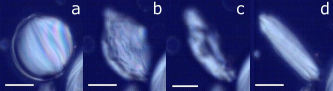
Under both bright field and polarized light, the smectic ellipsoids reveal a structure similar to that described for spherical smectic shells lopez2011nematic . The most outstanding feature of their optical texture is the presence of a set of meridional lines, which connect the two poles of the ellipsoid, dividing it into crescent domains, as shown in Fig. 1(e)-(f). These lines represent curvature walls where the director rotates by a constant angle. Consequently, the smectic layers, which are indicated by red lines in Fig. 1(f), are tilted in opposite directions in adjacent domains.
Adding an active nematic shell
To produce the ellipsoidal AN, the smectic droplets are dispersed in an aqueous active gel, where energy consuming kinesin motors cross-link and set into motion adjacent fluorescent-labeled microtubule bundles. In contrast to previous studies, where the active gel was encapsulated inside a droplet or vesicle keber2014 ; ellis2018 , here the active gel constitutes the continuous phase in which the droplets are dispersed. Through the depleting action of polyethylene glycol (PEG), the bundles gradually condense at the aqueous/8CB interface to progressively form an ellipsoidal AN sanchez2012 ; decamp2015 .
The active gel containing the passive droplets is introduced into a polyacrylamide-coated square glass capillary of mm inner width for observation. A constant supply of adenosine triphosphate (ATP) is ensured by the addition of phosphoenolpyruvate (PEP), which regenerates the activity of the nematic film. The chemical energy in the bulk can be renewed as often as needed through the dispersing solution, right before the activity is exhausted. An extended version of the protocol is provided in the Materials and Methods section.
The dynamic self-assembly of microtubules and motor clusters can be observed a few minutes after filling the capillary with the active mixture. The dispersing phase is populated with fluorescent filaments, tens of microns long, that continually extend and buckle, generating large active chaotic flows around the passive droplets. Initially, only a small portion of the microtubule bundles that contact the ellipsoidal surface is adsorbed. Their progressive accumulation on the droplet surface with time makes the active network stiffer, driving the active length scale to higher values martinez2019 ; kampmannControllingAdsorptionSemiflexible2013 ; stepanowAdsorptionSemiflexiblePolymer2001 . Our observations of approximately 50 droplets reveal two distinct states, the early quadrupolar state and the final dipolar state, both characterized by well-defined nematic order, large-scale flows, and remarkable periodic dynamics. The two states are described in the following section.
I Dynamic states of an active nematic ellipsoidal shell
Quadrupolar state: The transient dynamic state
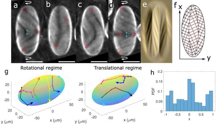
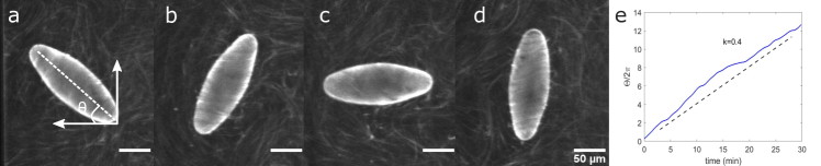
After approximately two hours of the experiment, under the given experimental conditions, the droplet surface has accumulated enough active material to sustain an organized state characterized by an ordered pattern of textures and flows. The dynamics of the system exhibits clear switching behavior, as indicated by the motion of defects. Specifically, the system commutes regularly between a long-lived regime of rotationally-moving defects that is interspersed with episodes where defects feature translational motion, as shown in Movie 1 in SI. A half-period of this dynamics is reproduced in Fig. 1 (a)-(d). Fig. 1(g) shows the trajectories described by the defects during a certain representative time for both the rotational and the translational regimes.
Fig. 1(a) and (d) show two snapshots of the droplet in the rotational regime. In this regime, each pole of the ellipsoid hosts a pair of defects, while the ellipsoid equator is decorated by a belt of and defects. Positive (self-propelled) and negative (dragged) defects are highlighted in red and cyan, respectively, in Fig. 1(a) and (d). It should be noted that only the defects on the visible side of the ellipsoid appear in these images, although full trajectories for all defects are represented in Fig. 1(g).
At the poles, the defects follow quasi iso-latitude trajectories, see Fig. 1(g) (left), while they maximize their separation distance due to elastic repulsion, as it will be discussed later. These defects turn about the ellipsoid major axis assembling swirls of the same handedness at the two poles of the ellipsoid, see Movie 1 in SI. The chirality of this motion is determined by spontaneous symmetry breaking and is randomly established when the AN is formed, remaining conserved over time.
To conciliate the defect dynamics at the poles, a defect belt appears simultaneously at the waist of the ellipsoid, setting a quadrupolar configuration of globally compensated torques. In the belt, oppositely charged defects form balanced pairs that do not contribute to the global topological charge of the system, which is , consistently with the global topological constraints for the ellipsoid hopfVektorfelderNdimensionalenMannigfaltigkeiten1927 ; poincareMemoireCourbesDefinies1881 . The optical texture obtained by fluorescence imaging shows the formation of transversal bands (nearly perpendicular to major ellipsoidal axis) displaying mirror symmetry with respect to equatorial plane, see Fig. 1(a) and (d). This pattern is compatible with the smectic structure of the substrate, shown in Fig. 1(e) and (f), with the smectic layers setting the easy flow directions guillamat2017 ; thijssenActiveNematicsAnisotropic2020 , see section 2 in SI for more details.
Because extensile ANs are intrinsically unstable against bend deformations, such a transversally aligned state is susceptible to instabilities. This instability results in the appearance of four crimps perpendicular to the aligned field, with two visible in Fig. 1(b) as dark longitudinal lines, while the other two are on the other side the droplet. This instability marks the onset of what we call the translational regime, where the two pairs of defects concurrently migrate along the crimps from pole to pole, locally reorienting the director field along the major axis of the ellipsoid, see Fig. 1(b), Fig. 1(g)(right) and Movie 1 in SI. As a result, the transversal bands get reoriented into longitudinal bands. The longitudinally aligned configuration is also unstable against bending, and the straight bands rapidly adopt parabolic shapes displaying mirror symmetry with respect to the equatorial plane, see Fig. 1(c). The equatorial belt with its accompanying population of positive and negative defects is progressively reconstituted, and the transversal bands reappear, see Fig. 1(d). This configuration is the same one shown in Fig. 1(b) with the pole defects having exchanged location. In the second half of the period, the whole process is repeated, and the two pairs of defects regain their initial location. This incessant switching between rotationally and translationally moving phases persists for up to nearly two more hours, during which the active material continues to accumulate at the surface of the ellipsoid.
To investigate the effect of curvature on the defect dynamics, we analyzed the positioning of the defects in terms of their probability distribution along the major axis of the ellipsoid, see Fig. 1(h). The histogram, which includes both positive and negative defects, aligns with two observations: firstly, positive defects tend to cluster around regions of maximal positive Gaussian curvature at the poles, and secondly, pairs of positive and negative defects with zero net topological charge persist in circulating along the equator. It is worth noting that this quadrupolar configuration is a transient state that eventually gives way to a more robust flow organization of a different symmetry, as described below.
Dipolar state: The final dynamic state
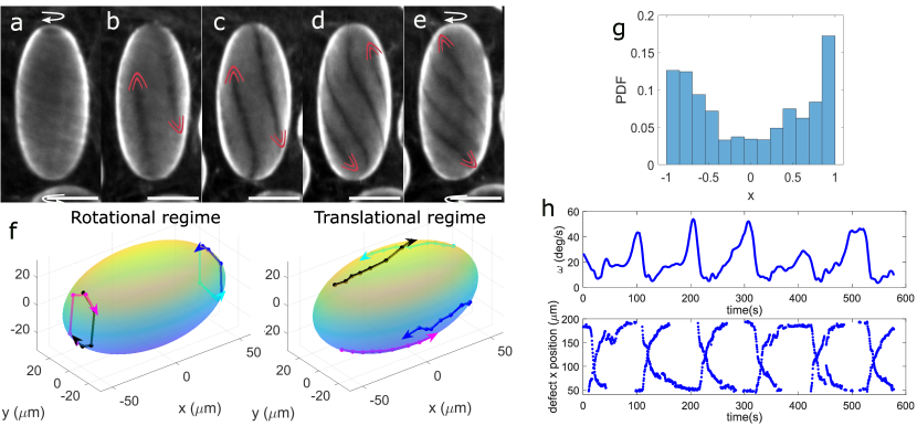
As time progresses, the amount of active material adsorbed on the ellipsoid surface appears to reach saturation. This likely makes the active material stiffer, thereby stabilizing the textures and flows at larger length scales. This results in the suppression of all non topologically required defects, and thus, in an asymptotic dynamic state regulated by the motion of only two pairs of defects. This final state displays some similarities and differences with the transient quadrupolar state described earlier. The most noticeable similarity is that the dynamics periodically switches between a rotational regime, where the two pairs of defects form swirls at the ellipsoid poles, and a translational regime, where the defects commute from pole to pole. The most important difference is that, during the rotational regime, the system displays dipolar rather than quadrupolar symmetry. A half-period of this new oscillatory dynamics is shown in Fig. 2(a)-(e), and representative defect trajectories for the rotational and translational regimes are plotted in Fig. 2(f).
The rotational regime, is characterized by the counter-rotation of the two pairs of defects around the poles, displaying opposite chirality, as depicted in Fig. 2(a), Fig. 2(f)(left) and Movie 2 in SI. This is in contrast to the quadrupolar state, where the defects co-rotate at the poles. In this counter-rotating configuration, there is no need for a defect belt at the equator to compensate the flow dynamics at the poles. This arrangement conforms to a dipolar structure, with loss of equatorial mirror symmetry, where the flows are well aligned along latitudinal lines, as shown in Fig. 2(a).
Bend instabilities act again to relax the accumulated stress on this aligned configuration, setting the onset of the translational regime, where longitudinal flows trigger the migration of defects towards opposite poles, as shown in Fig. 2(b)-(e) and Fig. 2(f)(right). Unlike in the quadrupolar state, where the straight longitudinal bands bend into a parabolic shape, the longitudinal bands here spontaneously tilt and eventually re-form into two swirls at the poles, completing the first half of the dynamics, see Fig. 2(b)-(e). In the second half, the entire process is repeated, and the defect pairs return to their initial positions. The chirality of the flows is preserved throughout the process. To visualize the defect trajectory over several dynamical cycles see Movie 3 and the left panel of Movie 4 in SI.
The positioning of defects along the major axis of the ellipsoid is shown in the histogram of Fig. 2(g), indicating that the defects preferentially accumulate at the poles where the Gaussian curvature is maximal, in agreement with theoretical predictions. Fig. 2(g) shows the average angular speed of defects as a function of their position along the major axis of the ellipsoid. A pattern of in-phase oscillations is clearly evidenced, where the maximum values of the angular velocity correspond to the rotational regime, and minimum values correspond to the translational regime, where the defects commute between poles. Additional details on the periodic oscillation of topological defects are presented in the SI, including the angular distances between defects as shown in Fig.S1 and Movie 4 in SI.
In summary, our findings demonstarte the existence of two oscillatory dynamic states in ANs confined to the ellipsoidal surface of a smectic droplet. Both gradients of Gaussian curvature and viscous anisotropy seem to control the active flows, leading to remarkably organized dynamic patterns. In the following section, we resort to numerical simulations to try to decouple the role of these two effects, otherwise impossible to disentangle in experiments.
II Coupling between curvature gradients, friction anisotropy, and hydrodynamic flows
Curvature effects
The final dipolar state observed experimentally is simulated by a thin shell of AN in a tangent plane between two concentric ellipsoids. Initially, we neglect the effects of the underlying smectic layers and focus on the impact of curvature gradients on the trajectories and dynamics of defects.
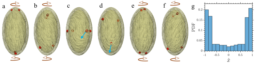
In the absence of active stresses, each pole is occupied by a pair of defects, with the director field tangentially aligned along the major axis of the ellipsoid to minimize elastic free energy. This configuration allows for a nearly uniform alignment of the director field in regions with low curvature. The active stresses bring the system out of this equilibrium configuration, and the defects start to rotate indefinitely on the antipodal points of a circumference centered at each pole of the ellipsoid, see Movie 5 in SI for a visual representation of this process. Away from the poles, the director field adopts a steady configuration with a slight tilt relative to the major axis. As the activity strength increases, the defects rotate faster, and the director field tilts further from the major axis. Similar to our experimental observations, when the activity surpasses a critical value, the defects display spiral trajectories and migrate toward opposite poles. The system develops well-organized spatio-temporal patterns, with defect dynamics that periodically switch from a circulation-dominant motion at the regions of maximal curvature, to linear translation near the equatorial plane, see Movie 6 in SI. Note that defects maintain their sense of rotation as they travel towards the opposite side of the ellipsoid, resulting in an inversion of the handedness at the poles every half-period, as shown in the sequence of images in Fig. 3(a)-(f). We further explore the residence time of the defects through a probability distribution function for finding defects along the major axis of the active system. Fig. 3(g) reveals that defects are primarily found in the regions of maximum Gaussian curvature. At the higher values of activity, the residence time at the poles decreases, and the histogram shown in Fig. 3 becomes more uniform.
The dynamics described in these simulations, which we refer to as frictionless system simulations, reproduce the periodic commutation between the rotational and translational regimes. However, in contrast with experiments, there is an inversion of the handedness at the poles every half period. Therefore, the experimental final state shown in Fig. 2 cannot be explained solely on the grounds of geometric considerations, and other parameters involved in the steering of the defects’ pathways must be examined. Indeed, the smectic droplet under the AN shell displays a textured surface. As discussed in the Supporting Information, we believe that the complex dynamics of the active system and the trajectories of the self-propelled defects are influenced by the anisotropic friction enforced by the smectic substrate. To address this question, in the next section, we consider the effect of anisotropic friction in our simulations.
Role of friction anisotropy
The effect of the smectic layers in contact with the AN is accounted for by adding a frictional damping force to the equations of motion that penalizes the fluid flow along certain directions, with a strength defined through a diagonal tensor . More details about this approach can be found in Section 2 of SI, where we discuss the role of frictional damping in the regulation of planar active flows. We first consider a uniform frictional pattern that penalizes flow along the long axis of the shell, aiming to mimic the structure of smectic layers, which provide an easy flow direction roughly parallel to the equatorial plane, see red lines in Fig. 1(f). In agreement with experiments, we observe topological defects organized in pairs at the poles, about the major axis of the ellipsoid. As defects spin around each other, the director field gets slightly tilted away from its original orientation. This simulation shows that the incorporation of anisotropic frictional damping forces improves agreement with the residence time distribution of the defects along the long axis observed in experiments, but fails to accurately predict the defects’ trajectories and, even more importantly, the handedness of rotation of the defects at the poles, see Movie 7 in SI.
Effect of external flow fields
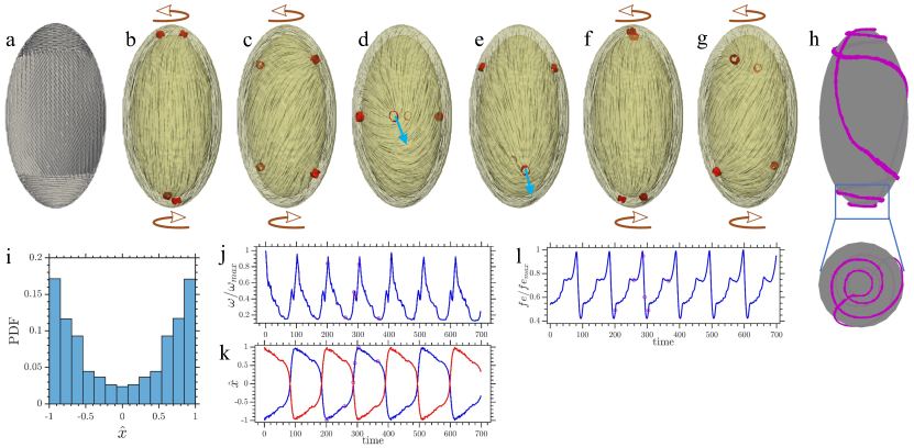
The discrepancies between the experimental and simulation results prompted us to adopt a non-uniform frictional pattern that embodies the complex interplay between the hydrodynamic interactions of the ellipsoidal droplets with the nearby capillary wall and the smectic structure of the inner ellipsoidal droplets. The proposed frictional pattern imposes two favorable paths that are almost mutually perpendicular. Near the poles, preferential lanes orient parallel to the equator, while on the main body, the easy direction is tilted with respect to the ellipsoid major axis, see Fig. 4(a). To rationalize this complex pattern, we need to investigate the rigid body behavior of the experimental droplets when they are dispersed in the active bath. Fig. 5 shows the temporal evolution of the orientation of the major axis of the droplet with respect to the horizontal axis. Although the confining volume inside the capillary is large compared to the droplet size, our analysis is restricted to two dimensions, since the buoyancy of the droplet keeps the droplet close to the top wall. One can appreciate that the rotation angle increases almost linearly with time for the final dipolar regime. These results suggest that the periodic final dynamics on the active shell is connected to the persistent rotations of the droplet, which arise from hydrodynamic interactions of the droplet with the confining boundary.
In order to shed light on these findings, we consider two defect pairs at the poles, while we adjust the boundary conditions close to the surface of the ellipsoid, to reproduce the experimental configuration (Movie 8 in SI). The spinning behavior of the defects induces strong shear flows in the thin gap between the droplet and the nearby substrate with opposite signs at the poles. This results in a net hydrodynamic torque that promotes a rigid body rotation of the ellipsoid perpendicularly to its major axis. Interestingly, as the ellipsoid continuously rotates, the surrounding hydrodynamic force couples to the anisotropic friction of the droplet, at the AN/smectic interface, leading to a resultant easy flow pattern that determines the navigation of defects. This hydrodynamic force is stronger at the equatorial region than at the poles, which are farther from the capillary wall, explaining the need to impose a non-uniform effective frictional pattern.
The hybrid template shown in Fig. 4(a) successfully replicates the dynamics observed for the final dynamic state in our experiments. Two pairs of defects periodically oscillate between two regimes, giving rise to vortices at the two opposite ends of the ellipsoid and to a linear translation away from the poles, as shown in Fig. 4(b)-(g). Note that this last configuration originates from the extensile nature of the active stresses, which induce diagonally oriented bending instabilities. Furthermore, the duration of the rotational regime being larger than that of the linear translation, leads to a higher likelihood for spotting defects at the poles, see Fig. 4(i), thereby explaining the propensity of defects for attraction to regions with higher positive Gaussian curvature displayed in Fig. 4(h). The pulse of the defect motion is further regulated by the anisotropic friction of the hybrid pattern which, in close agreement with experimental observations, see Fig. 2(g), amplifies the angular speed during circulatory motion at the poles and minimizes it near the equator of the droplet, as evidenced in Fig. 4(j)-(k). Note that the open circles on Fig. 4(j)-(l) correspond to time series snapshots displayed in Fig. 4(b)-(g). The continual oscillatory behavior between the two regimes can be understood by analyzing the temporal evolution of elastic free energy. At the poles, where defects reach the highest angular velocity, the elastic free energy is minimized. By injecting energy into the system, uniformly aligned active units are subject to bending instabilities, thereby enabling defects to escape from the poles and to travel diagonally toward the mid-plane, where the elastic free energy is maximized, as shown in Fig. 4(l). Notably, the chirality of the defect rotation persists over many periods, despite their continual exchange, in agreement with experiments. The final defect trajectories on AN ellipsoids are shown in Movie 9 in SI and are translated into the spatiotemporal variations of the nematic texture displayed in Movie 10 in SI.
III Final remarks and conclusions
We have presented an experimental system and a theoretical framework that enables to study in detail the dynamics of ANs confined to ellipsoidal smectic surfaces, where Gaussian curvature is non-uniform. The ability of the interfacial material to sense curvature gradients and the friction anisotropy imposed by the smectic substrate, drives periodic oscillations, self-regulated by external hydrodynamic forces that dictate remarkable chiral defect trajectories. Despite the periodic oscillation between a rotational and a translational regime enforced by the ellipsoidal geometry, the frictional anisotropy arising from the smectic texture of the droplet and hydrodynamic interactions with an external wall preserves the chirality of the defects.
The number of defects on the ellipsoidal surface evolves during the aging of the AN. Initially, the four topologically required defects are accompanied by additional pairs of and defects, which do not alter the total topological charge of the ellipsoid. In the rotational regime, the droplet displays quadrupolar symmetry: the two pairs of topologically required defects occupy the poles of the ellipsoid, while the additional defects form an equatorial belt. As time passes, this initial quadrupolar state is replaced by one with dipolar symmetry, resulting from the suppression of the defect belt. The reduction of the number of defects during the aging of the AN is likely due to an increase in the active length-scale, , resulting from the greater stiffness of the AN as the microtubule bundles adsorb at the interface (see Section 1 in SI).
The final dipolar dynamic state is robust against changes in the aspect ratio of the ellipsoid. Although for this study we have focused on ellipsoidal droplets with aspect ratio , we have also witnessed the emergence of a final dipolar state in ellipsoidal droplets with lower () and higher () aspect ratios. Such an oscillating chiral dipolar state, however, disappears when the smectic droplet has a spherical shape. In that case, the four defects follow non-regular trajectories and non-periodic dynamics. This behavior seems to stem from the more disordered organization of the smectic layers in the spherical geometry.
Our findings suggest that ellipsoidal active shells can serve to deepen our understanding of a wide range of biological processes, from tissue morphogenesis to mitosis maroudas2021 ; copenhagen2021 ; novak2018 ; zhu2017 , which rely on the coupling between defect dynamics and Gaussian curvature, or on the emergence of dipolar symmetry.
Materials and Methods
Production of smectic droplets
Microfluidic device fabrication
Ellipsoidal droplets were produced from thin double emulsions (W/LC/W) prepared using glass capillary microfluidics utadaMonodisperseDoubleEmulsions2005a . Our device is made of two cylindrical capillaries of 1mm outer diameter inserted into the opposite ends of a 1.02 mm square capillary. The two cylindrical capillaries are tapered on one side using a micropipette puller. Their tips are cut with a microforge to reach inner diameters of 60 m, for the injection capillary, and 120 m, for the collection capillary. The injection capillary, employed to inject the inner phase, is immersed in a solution containing 0.2v n-octadecyl-trimethoxysilane (376213, Sigma), 20v chloroform and 79.8v hexane, for 5 min to render its surface hydrophobic. Subsequently, the capillary is washed for 2min with chloroform, dried with compressed air and heated for at least 8 hours at . The cylindrical capillaries are then inserted facing each other into the square capillary. Their tips are aligned on the microscope, maintaining a separation distance of approximately 60 m. Dispensing needles are finally fixed at the three inlets of the device to inject the three phases constituting the double emulsions.
Production of smectic shells and ellipsoidal droplets
We introduce a 2wt Pluronic 127 solution through the injection capillary, and 8CB liquid crystal through the square capillary, which co-flow forming a composed jet at the entrance of the collection cylindrical capillary. The outer solution, composed of Pluronic 127 2wt and glycerol 60wt in Milli-Q water, is pumped from the other side of the square capillary, flow focusing the composed jet into the collection one. Such composed jet becomes unstable and breaks up into double emulsions. The device is locally heated at a temperature ranging between 33.5C and 40.5C, to maintain the 8CB LC in the nematic phase. We observe a stable dripping regime at typical flow rates of 1000L/hr, 400L/hr and 7500 L/hr for the inner, middle and outer fluids respectively. The shells are then collected in a solution with the same composition as the inner phase, preheated at 60C. In a second step, the collection vial is kept at room temperature for 15 minutes to trigger the N/SmA transition of the LC, inducing the bursting of the shells and the formation of the ellipsoidal droplets, as shown in FIGURE.
Microtubules polymerization
Polymerization was carried out by incubating at 37C for 30 min, an aqueous mixture of heterodimeric (,)-tubulin from bovine brain (Brandeis University Biological Materials Facility), M2B buffer (80 mM Pipes, 1 mM EGTA, and 2 mM ) (Sigma; P1851, E3889, and M4880, respectively), dithiothrethiol (43815, Sigma) reducing agent, and a non-hydrolysable guanosine triphosphate (GTP) analogue GMPCPP (guanosine-5-́ [(,)-methyleno] triphosphate) (NU-405, Jena Biosciences) that suppresses the dynamic instability of MTs. By adjusting GMPCPP concentration, tubulin heterodimers associate in a controlled way to produce a high-density suspension of short MTs (1–2 m). For fluorescence observation, 3 of the tubulin was labeled with Alexa 647 (A20006, Thermo Fisher Scientific). The final solution was kept at room temperature for 5 h, frozen in liquid nitrogen and stored at -80C for future use.
Kinesin expression
In this experiment, heavy-chain kinesin-1 K401-BCCP-6His from Drosophila melanogaster (truncated at residue 401, fused to biotin carboxyl carrier protein (BCCP), and labeled with six histidine tags) was expressed in Escherichia coli using the plasmid WC2 from the Gelles Laboratory (Brandeis University) and purified with a nickel column. After dialysis against 500 mM imidazole buffer, the concentration of the suspension was adjusted to (wt/v) with a sucrose solution and estimated by means of absorption spectroscopy. The final protein solution was stored at until used.
Active solution preparation
Kinesin/streptavidin motors clusters were prepared by incubating biotinylated kinesins with tetrameric streptavidin (43-4301, Invitrogen) at a 2:1 stochiometric ratio, for 30 min, under the reducing action of 2M DTT. The resulting suspension was mixed with a standard solution containing the M2B buffer, and a PEG (20 kDa; 95172, Sigma) depleting agent. To prevent protein denaturation and photobleaching during the fluorescence acquisition, 5,8 mM DTT, 0.2 mg/ml glucose oxidase, 0.04 mg/ml catalase, 2.1 mM Trolox and 3.5 mg/ml glucose antioxidants were incorporated to the mixture. The activity of the system was provided by chemical energy in the form of ATP (A2383, Sigma) (1.5 mM) and was constantly regenerated by the action of phosphoenolpyruvate (PEP) (P7127, Sigma) and pyruvate kinase/lactate dehydrogenase (PK/LDH) (434301, Invitrogen).
Sample preparation
The active gel was prepared by introducing 1L of microtubule suspension in 5L of active solution. Biocompatility and microtubule adsorption at the water/oil interface, in subsequent steps, were facilitated by the addition of 1L Pluronic F-127 (P2443, Sigma) 17wt and 1L Tween-80 (P1754, Sigma) 17wt surfactants to the previous solution. Afterward, 1L of the smectic droplets suspension was carefully incorporated. The final solution was gently introduced into a 0.6 mm square capillary, previously treated with an acrylamide brush. The latter coating was prepared by following reported protocolslau2009 to prevent the adhesion of the active material to the glass walls. The use of a square capillary of such dimensions has several advantages over a standard flow cell guillamat2018 . First, it allows us to manipulate small amounts of the active gel and to concentrate the droplets in a small volume. Second, the chemical energy (ATP) of the active bath can be renewed as often as needed since one of the capillary ends is kept open. Lastly, in the capillary, the evaporation of the active solution is reduced with respect to a standard flow cell.
Imaging
Active nematics observation, based on the fluorescence of labeled microtubules, was performed using a spinning disk confocal on a Nikon TI-E inverted microscope equipped with a Perfect Focus System (PFS) for continuous maintenance of focus. Images were typically captured every 500ms with a 10x objective and an Andor Zyla 4.2MP camera operated with NiS-Elements software. With the x10 objective, the confocal mode is not perfectly reached, giving rise to a depth of field of tens of microns, which allows us to focus the whole droplet hemisphere, a few microns in depth. Images for the 3D reconstruction of defect trajectories (Fig. 1(g), Fig. 2(f) and Movie 3 in SI) were acquired by simultaneously capturing 4 different planes, two of the top and two of the bottom planes of the droplet, at a rate of 0.7 frames/s.
Image analysis
Defect tracking was performed from confocal z-projection images, using the Fiji/imageJ plugin. For each frame of a movie, defects were identified as dark spots with comet-like shape. 2D Trajectories were further computed with a home-made MATLAB program. The angular speed of defects was calculated from their 3D trajectories, reconstructed by projecting 2D trajectories onto the ellipsoidal surface.
Simulation details
The systems considered here are described in terms of a nematic tensorial order parameter and a flow field . The standard theory of active nematodynamics is used to quantify their spatiotemporal evolution. For uniaxial systems, the nematic order parameter is written in the form where unit vector is the nematic director field and is an order parameter that measures the extent of orientational ordering. The evolution of this non-conserved order parameter obeys the strongly non-linear equation
| (1) |
where the advection term is generalized by , which accounts for the response of the nematic order parameter to the symmetric, , and antisymmetric, , parts of the velocity gradient tensor (). Here, , is the flow aligning parameter, chosen to be for flow aligning elongated units. The molecular field embodies the relaxational dynamics of the nematic, which drives the system toward the configuration with minimum Landau-de Gennes free energy
| (2) |
The free energy density, , is the sum of bulk and elastic energies given by:
| (3) | |||||
The relaxation rate is controlled by the collective rotational diffusion constant . The phenomenological coefficient sets the energy scale, controls the magnitude of the order parameter, and is the elastic constant in the one-elastic constant approximation. At the boundary surface with unit normal , the anchoring condition is imposed by adding a surface term to the free energy, . The fourth order Fournier-Galatola free energy density is adopted to apply the non-degenerate planar anchoring boundary condition
| (4) |
where controls the anchoring strength, , its projection to the surface , and .
The local fluid density and velocity are governed by the generalized incompressible Navier-Stokes equations, modified by a frictional dissipative term
| (5) |
The total asymmetric stress tensor is a sum of a passive and an active stress, and is the diagonal tensor describing frictional damping between the nematic fluid and the underlying substrate. The viscoelastic properties of the nematic are lumped in the passive stress, which is sum of the viscous and elastic terms
| (6) | |||||
and the active stress
| (7) |
Here, is the isotropic viscosity, is the isotropic bulk pressure, and measures the activity strength. A flow is generated when has spatial gradient with for extensile systems and for contractile ones. We employ a hybrid lattice Boltzmann method to solve the coupled governing partial differential equations (Eqs. 1, 5) marenduzzo2007 ; ravnik2013 ; zhang2018 ; sokolov2019 . The time integration is performed using an Euler forward scheme; the spatial derivatives are carried out using a second order central difference and the coupling is enforced by exchanging local fields between these algorithms at each time step. Simulations were performed on a three-dimensional lattice where the active layer were confined between two ellipsoid with a uniform shell of thickness lattice spacing and the inner prolate spheroid’s semi-minor and semi-major axes were chosen to be respectively, giving the aspect ratio of the inner shell to be slightly smaller than (uniform thickness of the shell results in a different aspect ratio for the outer shell, slightly smaller than ). All dimensions are expressed in lattice units. The medium viscosity was set to , and the collective rotational viscosity to . We chose the following parameters throughout the simulation , , (giving ). Planar anchoring conditions with strength and a no-slip velocity field at the surface of the inner and outer ellipsoids were enforced. The system was initialized with the director field tangentially oriented along the major axis. The thin shell confined between the ellipsoids was activated by applying uniform extensile active stresses to the nematic.
Acknowledgements.
This project has received funding from the European Union’s Horizon 2020 research and innovation program, under the Marie Sklodowska-Curie grant agreement No 754387, and from the French National Research Agency, under grant ANR-18-CE09-0028-02. The theoretical work was funded by the National Science Foundation, through the University of Chicago MRSEC. J.I.-M., and F.S. acknowledge funding from MICINN/AEI/10.13039/501100011033 (Grant No. PID2019-108842GB-C22). We thank B. Martínez-Prat, M. Pons, A. LeRoux, and G. Iruela (Universitat de Barcelona) for their assistance in the expression of motor proteins. We thank Brandeis University MRSEC Biosynthesis facility (supported by NSF MRSEC 2011846) for providing the tubulin.References
- (1) MC Marchetti, et al., Hydrodynamics of soft active matter. Rev. Mod. Phys. 85, 1143 (2013).
- (2) D Needleman, Z Dogic, Active matter at the interface between materials science and cell biology. Nat. Rev. Mater. 2, 17048 (2017).
- (3) A Doostmohammadi, J Ignés-Mullol, JM Yeomans, F Sagués, Active nematics. Nat. Commun. 9, 3246 (2018).
- (4) R Zhang, A Mozaffari, JJ de Pablo, Autonomous materials systems from active liquid crystals. Nat. Rev. Mater. 6, 437–453 (2021).
- (5) Y Maroudas-Sacks, et al., Topological defects in the nematic order of actin fibres as organization centres of hydra morphogenesis. Nat. Phys. 17, 251–259 (2021).
- (6) OJ Meacock, A Doostmohammadi, KR Foster, JM Yeomans, WM Durham, Bacteria solve the problem of crowding by moving slowly. Nat. Phys. 17, 205–210 (2021).
- (7) K Copenhagen, R Alert, NS Wingreen, JW Shaevitz, Topological defects promote layer formation in Myxococcus xanthus colonies. Nat. Phys. 17, 211–215 (2021).
- (8) MA Fardin, B Ladoux, Living proof of effective defects. Nat. Phys. 17, 172–173 (2021).
- (9) SP Thampi, R Golestanian, JM Yeomans, Active nematic materials with substrate friction. Phys. Rev. E 90, 062307 (2014).
- (10) A Doostmohammadi, MF Adamer, SP Thampi, JM Yeomans, Stabilization of active matter by flow-vortex lattices and defect ordering. Nat. Commun. 7, 10557 (2016).
- (11) K Thijssen, et al., Submersed micropatterned structures control active nematic flow, topology, and concentration. Proc. Natl. Acad. Sci. U.S.A. 118 (2021).
- (12) A Mozaffari, R Zhang, N Atzin, JJ de Pablo, Defect spirograph: Dynamical behavior of defects in spatially patterned active nematics. Phys. Rev. Lett. 126, 227801 (2021).
- (13) B Martínez-Prat, R Alert, F Meng, J Ignés-Mullol, J-F Joanny, J Casademunt, R Golestanian, F Sagués, Scaling Regimes of Active Turbulence with External Dissipation. Phys. Rev. X. 11, 031065 (2021).
- (14) P Guillamat, J Ignés-Mullol, F Sagués, Control of active liquid crystals with a magnetic field. Proc. Natl. Acad. Sci. U.S.A 113, 5498–5502 (2016).
- (15) P Guillamat, J Ignés-Mullol, F Sagués, Taming active turbulence with patterned soft interfaces. Nat. Commun. 8, 564 (2017).
- (16) K Thijssen, J Yeomans, A Doostmohammadi, Active nematics with anisotropic friction: the decisive role of the flow aligning parameter. Soft Matter 16, 2065–2074 (2020).
- (17) R Zhang, et al., Spatiotemporal control of liquid crystal structure and dynamics through activity patterning. Nat. Mater. 20, 875–882 (2021).
- (18) X Tang, JV Selinger, Alignment of a topological defect by an activity gradient. Phys. Rev. E 103, 022703 (2021).
- (19) R Zhang, A Mozaffari, JJ de Pablo, Logic operations with active topological defects. Sci. Adv. 8, eabg9060 (2022).
- (20) D Pearce, PW Ellis, A Fernandez-Nieves, L Giomi, Geometrical control of active turbulence in curved topographies. Phys. Rev. Lett. 122, 168002 (2019).
- (21) H Wioland, FG Woodhouse, J Dunkel, JO Kessler, RE Goldstein, Confinement stabilizes a bacterial suspension into a spiral vortex. Phys. Rev. Lett. 110, 268102 (2013).
- (22) M Ravnik, JM Yeomans, Confined active nematic flow in cylindrical capillaries. Phys. Rev. Lett. 110, 026001 (2013).
- (23) FC Keber, et al., Topology and dynamics of active nematic vesicles. Science 345, 1135–1139 (2014).
- (24) R Zhang, Y Zhou, M Rahimi, JJ de Pablo, Dynamic structure of active nematic shells. Nat. Commun. 7, 13483 (2016).
- (25) D Khoromskaia, GP Alexander, Vortex formation and dynamics of defects in active nematic shells. New J. Phys. 19, 103043 (2017).
- (26) KT Wu, et al., Transition from turbulent to coherent flows in confined three-dimensional active fluids. Science 355, eaal1979 (2017).
- (27) PW Ellis, et al., Curvature-induced defect unbinding and dynamics in active nematic toroids. Nat. Phys. 14, 85–90 (2018).
- (28) P Guillamat, et al., Active nematic emulsions. Sci. Adv. 4, eaao1470 (2018).
- (29) A Opathalage, et al., Self-organized dynamics and the transition to turbulence of confined active nematics. Proc. Natl. Acad. Sci. U.S.A. 116, 4788–4797 (2019).
- (30) J Hardoüin, J Laurent, T Lopez-Leon, J Ignés-Mullol, F Sagués, Active microfluidic transport in two-dimensional handlebodies. Soft Matter 16, 9230–9241 (2020).
- (31) M Rajabi, H Baza, T Turiv, OD Lavrentovich, Directional self-locomotion of active droplets enabled by nematic environment. Nat. Phys. 17, 260–266 (2021).
- (32) T Lubensky, J Prost, Orientational order and vesicle shape. Journal de Physique II 2, 371–382 (1992).
- (33) T Lopez-Leon, V Koning, K Devaiah, V Vitelli, A Fernandez-Nieves, Frustrated nematic order in spherical geometries. Nat. Phys. 7, 391–394 (2011).
- (34) YH Zhang, M Deserno, ZC Tu, Dynamics of active nematic defects on the surface of a sphere. Phys. Rev. E 102, 012607 (2020).
- (35) AT Brown, A theoretical phase diagram for an active nematic on a spherical surface. Soft Matter 16, 4682–4691 (2020).
- (36) R Sknepnek, S Henkes, Active swarms on a sphere. Phys. Rev. E 91, 022306 (2015).
- (37) LM Janssen, A Kaiser, H Löwen, Aging and rejuvenation of active matter under topological constraints. Sci Rep. 7, 5667 (2017).
- (38) S Henkes, MC Marchetti, R Sknepnek, Dynamical patterns in nematic active matter on a sphere. Phys. Rev. E 97, 042605 (2018).
- (39) P Castro-Villarreal, FJ Sevilla, Active motion on curved surfaces. Phys. Rev. E 97, 052605 (2018).
- (40) F Alaimo, C Köhler, A Voigt, Curvature controlled defect dynamics in topological active nematics. Sci Rep. 7, 5211 (2017).
- (41) S Ehrig, J Ferracci, R Weinkamer, JW Dunlop, Curvature-controlled defect dynamics in active systems. Phys. Rev. E 95, 062609 (2017).
- (42) MJ Bowick, L Giomi, Two-dimensional matter: Order, curvature and defects. Adv. Phys. 58, 449–563 (2009).
- (43) MA Bates, G Skačej, C Zannoni, Defects and ordering in nematic coatings on uniaxial and biaxial colloids. Soft Matter 6, 655–663 (2010).
- (44) S Kralj, R Rosso, EG Virga, Curvature control of valence on nematic shells. Soft matter 7, 670–683 (2011).
- (45) E De Oliveira, I De Oliveira, M Lyra, L Mirantsev, Tunable topological valence in nematic shells on spherocylindrical colloidal particles. Phys. Rev. E 93, 012703 (2016).
- (46) D Jesenek, S Kralj, R Rosso, EG Virga, Defect unbinding on a toroidal nematic shell. Soft matter 11, 2434–2444 (2015).
- (47) EJ Hemingway, P Mishra, MC Marchetti, SM Fielding, Correlation lengths in hydrodynamic models of active nematics. Soft Matter 12, 7943–7952 (2016).
- (48) AS Utada, et al., Monodisperse Double Emulsions Generated from a Microcapillary Device. Science 308, 537–541 (2005).
- (49) T Lopez-Leon, A Fernandez-Nieves, M Nobili, C Blanc, Nematic-smectic transition in spherical shells. Phys. Rev. Lett. 106, 247802 (2011).
- (50) T Sanchez, DT Chen, SJ DeCamp, M Heymann, Z Dogic, Spontaneous motion in hierarchically assembled active matter. Nature 491, 431–434 (2012).
- (51) SJ DeCamp, GS Redner, A Baskaran, MF Hagan, Z Dogic, Orientational order of motile defects in active nematics. Nat. Mater. 14, 1110–1115 (2015).
- (52) B Martínez-Prat, J Ignés-Mullol, J Casademunt, F Sagués, Selection mechanism at the onset of active turbulence. Nat. Phys. 15, 362–366 (2019).
- (53) T Kampmann, H Boltz, J Kierfeld, Controlling adsorption of semiflexible polymers on planar and curved substrates. J. Chem. Phys. 139, 034903 (2013).
- (54) S Stepanow, Adsorption of a semiflexible polymer onto interfaces and surfaces. J. Chem. Phys. 115, 1565-1568 (2001).
- (55) H Poincaré, Mémoire sur les courbes définies par une équation différentielle (I). Journal de Mathématiques Pures et Appliquées 7, 375–422 (1881).
- (56) H Hopf, Vektorfelder in n-dimensionalen-Mannigfaltigkeiten. Mathematische Annalen 96, 225–250 (1927).
- (57) M Novak, et al., The mitotic spindle is chiral due to torques within microtubule bundles. Nat. Commun. 9, 3571 (2018).
- (58) N Zhu, HK Kwong, Y Bao, TH Chen, Chiral orientation of skeletal muscle cells requires rigid substrate. Micromachines 8, 181 (2017).
- (59) A Lau, A Prasad, Z Dogic, Condensation of isolated semi-flexible filaments driven by depletion interactions. Europhys. Lett. 87, 48006 (2009).
- (60) D Marenduzzo, E Orlandini, JM Yeomans, Hydrodynamics and rheology of active liquid crystals: a numerical investigation. Phys. Rev. Lett. 98, 118102 (2007).
- (61) R Zhang, N Kumar, JL Ross, ML Gardel, JJ de Pablo, Interplay of structure, elasticity, and dynamics in actin-based nematic materials. Proc. Natl. Acad. Sci. U.S.A. 115, E124–E133 (2018).
- (62) A Sokolov, A Mozaffari, R Zhang, JJ de Pablo, A Snezhko, Emergence of radial tree of bend stripes in active nematics. Phys. Rev. X 9, 031014 (2019).
Dynamics of active defects on the anisotropic surface of an ellipsoidal droplet
Supplementary Information
Martina Clairand1,∗, Ali Mozaffari2,3,∗, Jerôme Hardoüin4,5, Rui Zhang2,6, Claire Doré1, Jordi Ignés-Mullol4,5, Francesc Sagués4,5, Juan J. de Pablo2,7, Teresa Lopez-Leon1
1 Laboratoire Gulliver, UMR CNRS 7083, ESPCI Paris, PSL Research University, 75005 Paris, France
2 Pritzker School of Molecular Engineering, The University of Chicago, Chicago, Illinois
60637, USA
3 OpenEye Scientific, Cadence Molecular Sciences, Boston, Massachusetts 02114, USA
4 Departament de Química Física, Universitat de Barcelona, 08028 Barcelona, Spain
5 Institute of Nanoscience and Nanotechnology, Universitat de Barcelona, 08028 Barcelona, Spain
6Department of Physics, Hong Kong University of Science and Technology, Clear Water Bay, Kowloon, Hong Kong
7Center for Molecular Engineering, Argonne National Laboratory, Lemont, Illinois
60439, USA
(Dated: )
Oscillatory dynamics of topological defects in the final dipolar state
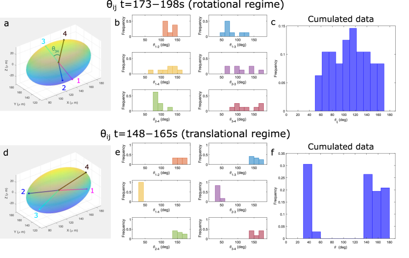
To visualize the oscillatory dynamics of the AN flows in the final dipolar dynamical state, we have reconstructed the 3D-trajectory of the topological defects at the surface of an ellipsoid (see Fig.2 (f) of the main text, Movie 3 and the left panel in Movie 4 in SI). The representations were obtained by tracking simultaneously the defects on the top and bottom planes of the droplet (left panel of Movie 3 in SI), and projecting the resulting 2D trajectories on each of the two hemi-ellipsoidal surfaces, via a custom MATLAB program. As shown in Movie 3 and Movie 4, oscillations appear as periodic cycles of defect rotation at the poles and translation from pole to pole. The defect configuration of each regime is well-characterized by the distribution of , which refers to the central angular distance between defect pairs (Fig. S1). During the translational regime (Fig. S1 (a-c)), the distribution is homogeneous, with comprised between and and a maximal occurrence near . In the rotational regime (Fig. S1 (d-f)), on the other hand, defect pairs near the poles are separated by the angles and , with values below , while opposite pairs of defects form angles ,, and , above .
Simulation of active nematics on a 2D planar interface with frictional forces
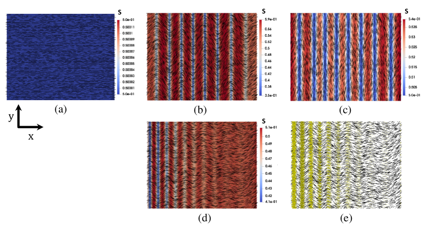
We use numerical simulations to investigate how frictional forces control the dynamics of active nematics confined to a 2D planar interface. Initially, the director field is aligned along the -axis, as shown in Fig. S2 (a). Once the extensile active force is applied on the system, bending instabilities yield the formation of topological defects and chaotic flows. However, the presence of frictional forces leads to regular spatio-temporal patterns in the flow and director fields, as shown in the remaining panels of Fig. S2.
We first examined the effect of incorporating an anisotropic frictional pattern where only the component of the tensorial damping term in Eq.5 is non-zero. This setup penalizes the flows parallel to the initial orientation of the director field (-axis) and provides an easy flow direction along the -axis. Initially, the system shows bending instabilities similar to those in the previous case, see Fig. S2 (b). However, due to the large elastic distortions and high shear stresses generated as a result of the formation of these elastic bands, at later times, the director undergoes additional distortions. The system finds it more energetically favorable to unbind pairs of defects and to form a stable nematic pattern with dominant splay deformation. The frictional forces imposed along the -axis impedes the growth of additional bending instabilities and the nematic structure remains stable, as shown in Fig. S2 (c). This result is closely related to the experimental observation made by Guillamat et al in a microtubule-kinesin active nematic in contact with 8CB liquid crystal aligned via a magnetic field, where the high friction anisotropy imposed by the smectic layer led to the formation of anti-parallel flowing lanes guillamat2016 .
We then consider a case where the substrate in contact with the active layer does not impose a directional frictional anisotropy but a gradient in the friction magnitude. Here, the strength of the frictional damping force, grows linearly along the -axis. This scenario can be achieved by having the active layer in contact with a substrate of varying viscosity. Fig. S2 (d-e) shows that lanes of anti-parallel flow develop with bands of different width. At the higher value of friction strength (higher values of in Fig. S2 (d-e)), the suppression of momentum propagation results in bands with a larger width along with smaller values of velocity.
With these examples we have demonstrated that by controlling the friction at a substrate, the otherwise chaotic active nematic flows can be tamed to precisely sculpt well-ordered spatio-temporal states and flow fields.
References
- (1) P Guillamat, J Ignés-Mullol, F Sagués, Control of active liquid crystals with a magnetic field. Proc. Natl. Acad. Sci. U.S.A 113, 5498–5502 (2016).