Localization-based OFDM framework for RIS-aided systems
Abstract
Efficient integration of reconfigurable intelligent surfaces (RISs) into the current wireless network standard is not a trivial task due to the overhead generated by performing channel estimation (CE) and phase-shift optimization. In this paper, we propose a framework enabling the coexistence between orthogonal-frequency division multiplexing (OFDM) and RIS technologies. Instead of wasting communication symbols for the CE and optimization, the proposed framework exploits the localization information obtainable by RIS-aided communications to provide a robust allocation strategy for user multiplexing. The results demonstrate the effectiveness of the proposed approach with respect to CE-based transmission methods.
Index Terms:
Reconfigurable intelligent surfaces, OFDM, robust optimization, resource allocationI Introduction
Reconfigurable intelligent surfaces (RISs) are considered among the enabling technologies for the next-generation (6G) of wireless networks due to their ability to control the wireless propagation environment [1].
In recent years, many research works have shown the capabilities of the RIS in terms of improved coverage, data rate, and mitigation of multi-user interference through accurate phase-shift optimization [2]. However, only a few works have focused on integrating the RIS into the existing communication protocols. To the best of the authors’ knowledge, the authors of [3] were the first to consider RIS-aided communications framework employing orthogonal-frequency division multiplexing (OFDM), proposing a joint channel estimation (CE) and RIS phase-shift optimization framework showing outstanding performance for a single user equipment (UE) scenario. Nevertheless, in multi-user systems, RIS channel estimation procedures need pilot sequences whose length is proportional to the number of RIS elements and the number of UEs in the system [4, 2]. Hence, the CE procedure may lead to an unfeasible overhead when serving a large number of users.
From a different perspective, the recent literature has shown the capability of using RIS to enhance the performance of localization algorithms [1], and even enable new localization procedures not feasible without an RIS [5]. Considering the relevance that integrated sensing and communication (ISAC) has gained to enable the connected intelligence promised by the 6G, it is natural to imagine the use of the (improved) localization information available in RIS-aided networks to help the scheduling decision: instead of wasting time for exchanging CE pilot sequences, the knowledge of the UEs position can be used to optimize the data transmission. In this line, the authors of [6] proposed a RIS phase shift optimization based on localization information able to maximize the average spectral efficiency. Furthermore, in [7], the authors provide a time division duplexing (TDD) framework to integrate communication and localization in RIS-aided systems.
This paper proposes an OFDM scheduling protocol for RIS-aided systems based on localization information. Following the time horizon provided by the OFDM structure, our RIS loads different configurations in different time slots, enhancing incoming signals in a space division manner. The configurations are stored in a codebook, optimized to provide maximum gain within the configuration subspaces. The propagation scenario analyzed is far-field, with both direct and reflected paths present. We assume that the direct path is Rician distributed, while the RIS reflected path is Line-of-Sight (LoS). We show that the position can be used to determine a robust allocation strategy able to effectively utilize the designed codebook while keeping the OFDM structure unchanged. The performance is tested using max-rate and max-min allocation in both throughput and fairness and compared with the performance of a RIS-aided system able to recover perfect channel state information (CSI) through a minimum overhead CE procedure. Even considering the overhead obtained by the localization signaling needed to infer the position of the UE in the system, we show that the proposed approach outperforms the CSI-based system.111The simulation code for the paper is available at https://github.com/lostinafro/ris-ofdm-loca-scheduling
Notation
Integer sets are denoted by calligraphic letters with cardinality . The complex Gaussian distribution is with mean and covariance matrix ; non-central -squared distribution with non-centrality and degrees of freedom is . Lowercase boldface letters denote column vectors ; represents the element-wise vector multiplication. The identity matrix of size is , and is a vector of zeros.
II System model
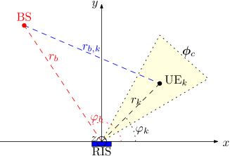
We consider an uplink (UL) RIS-aided communication scenario, where a single-antenna base station (BS), an RIS, and set of single-antenna UEs are present. The BS is assumed to have perfect knowledge of the UEs’ position, and it uses this information to make scheduling decisions.
Geometry
The scenario is shown in Fig. 1, where the axis points to the outgoing direction of the plane. The center of the RIS is positioned at the origin of the axis, parallel to and axis. The dimensions of the RIS are and , and it is formed by elements, having distance and , on the and axes respectively. We enumerate each element following the direction of the and axis, i.e., the element has center position , , . The BS is positioned at . The users are collected in the set , . Each user is positioned at . The distance between UE and BS is denoted as . For simplicity of presentation, the elevation angle of both BS and UE is set as , i.e., UEs, BS and RIS lay on the same plane. The design principles given here can be extended for different elevation angles.
RIS phase shift profile
Each element of the RIS is able to imprint a phase shift on the impinging electromagnetic wave222The RIS is considered ideal, i.e., no attenuation or inter-element coupling is considered for mathematical tractability.. The overall phase shift profile is a vector denoted as , collecting the phase shifts for each RIS’ element. A configuration codebook collects the pre-determined phase shift profiles that can be loaded by the RIS, i.e., RIS and BS share the knowledge of a finite set of RIS’ configurations. When configuration is loaded, the correspondent RIS phase shift profile is designed to enhance the signal coming from a sector of the area, steering it towards the BS.
Proposed data-frame structure
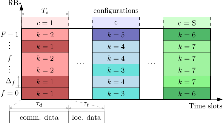
The time-frequency resource grid is formed by time slots, collected in the set , each of duration , and resource blocks (RBs), collected in the set , each having bandwidth . The first RB is assumed to have central frequency , i.e., wavelength , where denotes the propagation velocity of the wave. Hence, the wavelength of RB is . It is assumed that the coherence time is longer than the overall frame duration in time (), while is lower than the coherence bandwidth.
Each time slot comprises OFDM symbols; are reserved for data communication, while are reserved for localization waveform the BS can use to keep track of the user position through a specific algorithm, such as [5]. It is assumed that the BS can recover the position of each user without any error333The design of the localization algorithm is out of the scope of the paper. Future works will focus on the trade-off of localization and communication performance in this setting, taking into account the impact of the localization error in the overall scheduling strategy..
At the beginning of each time slot, the RIS loads a single configuration , which is kept for the whole time slot duration. It is assumed that the time for loading a configuration is lower than the time of the cyclic prefix (CP) of the first OFDM symbol, and hence the RIS switching through different configurations does not influence the transmitted data (differently from, e.g., [8]). UEs are multiplexed through orthogonal slot-RB allocation, as shown in the time-frequency example given in Fig. 2.
Signal model
Consider that a single time-frequency resource related to configuration and frequency is exclusively allocated to user . On that resource, the user transmits a symbols , , , with power . The received signal at the BS is given by
| (1) |
where we indicated as the direct BS-UE channel, as the BS-RIS-UE reflected channel while the RIS has configuration loaded, and as the additive white gaussian noise (AWGN) at the BS receiver side. The signal-to-noise ratio (SNR) at the RB is given by
| (2) |
where is the phase shift that the signal experiences through the direct path, while is the phase shift experienced through the reflective path comprehending the one imprinted by the RIS configuration . The SNR of a single resource is maximized when . In the following, the assumption made on the channels and their formulation is given.
Assumption 1.
In this work, the direct channel coefficient is assumed to be Rician distributed, i.e., it has a deterministic LoS component and a random Non-Line-of-Sight (NLoS) component; the reflected path has only a dominant deterministic LoS component.
According to Assumption 1, the vector collecting the channel of the direct and reflective paths for all the RBs are
| (3) | |||
| (4) |
where is the random NLoS component; the deterministic LoS component is represented by
| (5) |
which collects the different propagation delays for different RBs; is the Rician factor previously estimated in the environment [9]; the path loss is [10]
| (6) |
having path-loss exponent 444Here, we used the common assumption that the variation of the path loss on the different wavelengths is negligible. and BS and UE antenna gains and , respectively; finally, is the normalized array factor (AF) generated by configuration .
III Resource grid and codebook design
In this section, we propose a design of the codebook to cover the whole area of interest. We remark that the element phase shift term influences all the RBs in the same manner555Circuital-based RIS models show that the RIS phase shift is affected by the frequency [13]. We neglect this effect to concisely show the design principle of the proposed protocol, considering that this dependency is deterministic and can be straightforwardly included.; hence, we will design the phase shift for a single RB, e.g., , study the impact on the other frequencies, and finally provide a design of the configuration codebook to employ for the proposed paradigm.
III-A General phase-shift formulation
For each configuration , we aim to maximize the AF gain when the received signal comes from a specific angular direction , for . By the observation of eq. (7), we can infer that each element phase shift needs to compensate for the phase shift generated by the BS position, while let each term of the sum to be 1 when . Accordingly, we can design the phase shifts as
| (8) |
with
| (9) |
being set to cancel the residual phase shift given by the geometry of the RIS. Indeed, plugging (8)-(9) into eq. (7) yields
| (10) | ||||
which is maximized for if a user is located at . For , this design can remove the contribution of the AF in the overall phase of the reflective channel . Indeed, by means of finite geometric series, eq. (10) can be rewritten as [11, 12]
| (11) |
where . Eq. (11) shows that , i.e., where is the Heaviside step function. Moreover, eq. (11) is the AF of the uniform linear phased array, being negative only outside of the main lobe region [11]. Hence, as long as the allocated configuration and RBs guarantee that the normalized AF works in the main lobe for the user , the contribution of the AF in the total phase is zero, i.e., .
III-B Frequency dependency
Regarding the influence on the frequency domain, we can prove experimentally that the AF varies slowly with the different RBs. A depiction of the frequency dependence of the AF is given in Fig. 3; the plot is made for different angular positions and assuming that , , to show the frequency dependence only. It can be seen that the position of the nulls of the function change according to the user position: the higher the azimuth angle, the narrower the main lobe666Remark that for particular positions , the AF never changes, regardless the employed RB.. Nevertheless, even considering the user at °, to obtain a reduction of 20% of the array gain, a frequency hop of MHz from the first RB must be realized, i.e, RBs with numerology 0 [14]. Therefore, we assume that the system has a number of available RBs to minimize the effect of the variation of the AF gain while guaranteeing that the contribution on the phase provided by the design (8) is zero, regardless of the selected RB.
III-C Codebook design
To cover the whole area of interest using the proposed framework, we resort to an approach that enables us to create a codebook containing at least one configuration providing an AF gain of at least to any UE regardless of its position, for . To do so, we design a codebook having every consequent configuration to overlap at the angular direction that provides the desired minimum gain, similar to [8]. For the sake of simplicity, we set dB, but any other values can be considered with the same procedure. With negligible error, we approximate the main lobe of eq. (11) by a function [11, 8]. Thus, we find the argument such that , which gives the value of . Therefore, when
Now, define as and the angular directions where the AF gain for configuration is half of the maximum, where ; to let consequent configurations having overlapping half power angular direction, we impose , . Accordingly, the set of equation to satisfy is
| (12) |
To cover the whole area, we impose that , meaning that the first configuration has the half power direction towards the right limit of the area of interest. Therefore, by solving (12) in an iterative manner, we obtain
| (13) |
where the number of configurations to cover the area is
| (14) |
A visualization of the obtained codebook is given in Fig. 4.
IV Resource allocation
In this section, we present the allocation scheduling process based on the proposed framework.
Given the set of configurations , the set of available of RBs, and the position information of each user, we know the value of the deterministic part of the SNR for all the UEs, RBs and time-slots. Nevertheless, the actual SNR is a random variable: to provide a feasible communication rate, the spectral efficiency (SE) set for the data transmission must be lower than the achievable capacity. To overcome this issue, we define the -robust SE as the SE that assures that the data transmitted by UE on RB and under configuration are successfully decoded with probability , i.e., the SE satisfying
| (15) |
Lemma 1.
| (17) |
Proof.
In practice, knowing the deterministic part of the SNR allows us to compute the -robust SE for all the resources and use it to optimize the allocation. To this purpose, we further define the allocation variable , mapping each user with the corresponding time-frequency resource. Accordingly, the total SE of user is
| (18) |
To evaluate the system performance with different metrics, we focus on two classical problems: maximize the overall rate, and maximize the minimum rate.
Max-Rate
In order to maximize the overall communication throughput, we define the following optimization problem:
| (19) | ||||
| s.t. | (19.a) | |||
| (19.b) |
where constraint (19.a) enforces the integer condition on the allocation variable, and constraint (19.b) assures that each time-frequency resource is allocated to at most one user.
The optimal solution of problem (19) is trivial: each RB of each slot is given to the UE providing the highest -robust SE, i.e.,
| (20) |
Max-min
In order to maximize the minimum rate between the users, we define the following optimization problem:
| (21) |
In this case, the problem is not trivial, and an optimal solution is hard to achieve. Therefore, we resort to a heuristic scheme that iteratively allocates the RB to the UE with the smallest rate [15]. The procedure is given in Algorithm 1, where , and represents the double index in lexicographic order.
IV-A Joint vs. sequential allocation
The scheduling procedure described performs both the -robust rates evaluation and the allocation operation on the entire dimension of the tensor . While the optimization problems presented here are relatively simple, performing more complicated resource allocation schemes may be computationally infeasible in a real application. In those cases, we can resort to a sequential allocation: time slot allocation first, followed by RB allocation.
The time slot allocation is determined by comparing the angular position of the user with the angular pointing of the various configuration. Denoting as the configuration employed by user , we have
| (22) |
and the time slot allocation is obtained straightforwardly.
For the RB allocation, let us denote as the subset of the users allocated to configuration . Consequently, we can apply eq. (20) for a max-rate allocation, taking care of substituting to in the rule. Similarly, Algorithm 1 can be applied for max-min allocations, where now , and represents the index .
V Numerical results
| Parameter | Symbol | Value |
|---|---|---|
| Outer/inner radius | m | |
| BS position (Cartesian) | m | |
| RIS element spacing | ||
| Number of RIS elements | 10 | |
| Central frequency | 1.8 GHz | |
| Bandwidth | kHz | |
| RBs | 50 | |
| Time slots/Configurations | ||
| OFDM symbols | 14 | |
| OFDM data/localization symbols | 7, 7 | |
| Success probability | % | |
| Antenna gains | dB | |
| Path loss exponent | ||
| Reference path gain | dB |
In this section, we present our numerical results. To perform the simulations, we have deployed the users randomly in a ring having inner radius and outer radius . The parameters we used are listed in Table I. As a benchmark, we consider the CSI-based approach working as follows: before the communication data phase, minimal length pilot sequences [4] are sent by the UEs to perform CE, one complex symbol per OFDM symbol to cover all the RBs. The estimation is assumed to be noise-free, i.e., the BS has perfect CSI after the CE ends. In the following, we label csi the performance obtained by the CSI-based scheme, while jnt and seq the localization-based joint and sequential allocation performance. The main performance metrics used are the average total throughput obtained by the system, and Jain’s fairness index, given by
| (23) |
In eq. (23), represent the efficiency of the -th communication scheme given by and , where [4].
Fig. 5 shows the performance obtained by the max-rate allocation schemes. Fig. 5(a) presents the throughput as a function of the number of users when dB, while Fig. 5(b) as a function of the Rician factor when . Both localization-based paradigms outperform the CSI-based scheme. In particular, when the system is in an overloaded state, i.e., , the CE overhead increases in a prohibitive manner. Interestingly, even with a low number of users, the localization-based schemes achieve superior performance for every value of under test.
Fig. 6 shows the performance of the min-max allocation schemes. Fig. 6(a) presents the fairness as a function of the number of users when dB, while Fig. 6(b) the average throughput per user as a function of the Rician factor when . In this case, the fairness performance of jnt and the csi are comparable, both outperforming seq for every . Regarding the average throughput per user, the localization-based schemes outperform csi. In particular, jnt has a clear advantage to csi reaching similar fairness, but with an average rate more than doubled.
VI Conclusions
This paper proposed an OFDM framework for RIS-aided communications that exploit localization information to perform a robust resource allocation in a multi-user scenario. The results presented show the effectiveness of the proposed approach w.r.t. CE-based solutions. While the proposed solution is promising, the impact of localization accuracy needs to be studied by investigating the trade-off of transmitting data and localization symbols.
References
- [1] E. Björnson, et al., “Reconfigurable intelligent surfaces: A signal processing perspective with wireless applications,” IEEE Signal Processing Mag., vol. 39, no. 2, pp. 135–158, 2022.
- [2] M. Jian et al., “Reconfigurable intelligent surfaces for wireless communications: Overview of hardware designs, channel models, and estimation techniques,” Intelligent and Converged Networks, vol. 3, no. 1, pp. 1–32, 2022.
- [3] B. Zheng and R. Zhang, “Intelligent reflecting surface-enhanced ofdm: Channel estimation and reflection optimization,” IEEE Wireless Communications Letters, vol. 9, no. 4, pp. 518–522, 2020.
- [4] Z. Wang et al., “Channel estimation for intelligent reflecting surface assisted multiuser communications: Framework, algorithms, and analysis,” IEEE Transactions on Wireless Communications, vol. 19, no. 10, pp. 6607–6620, 2020.
- [5] K. Keykhosravi, M. F. Keskin, G. Seco-Granados, and H. Wymeersch, “SISO RIS-enabled joint 3d downlink localization and synchronization,” in ICC 2021-IEEE International Conference on Communications. IEEE, 2021, pp. 1–6.
- [6] A. Abrardo et al., “Intelligent reflecting surfaces: Sum-rate optimization based on statistical position information,” IEEE Trans. on Communications, vol. 69, no. 10, pp. 7121–7136, 2021.
- [7] R. Wang, Z. Xing, and E. Liu, “Joint location and communication study for intelligent reflecting surface aided wireless communication system,” arXiv preprint arXiv:2103.01063, 2021.
- [8] V. Croisfelt et al., “Random access protocol with channel oracle enabled by a reconfigurable intelligent surface,” 2022. [Online]. Available: https://arxiv.org/abs/2210.04230
- [9] L. Greenstein et al., “Moment-method estimation of the ricean k-factor,” IEEE Communications Letters, vol. 3, no. 6, pp. 175–176, 1999.
- [10] A. Albanese, F. Devoti, V. Sciancalepore et al., “MARISA: A self-configuring metasurfaces absorption and reflection solution towards 6G,” in IEEE INFOCOM 2022-IEEE Conference on Computer Communications. IEEE, 2022, pp. 250–259.
- [11] C. A. Balanis, Antenna theory: analysis and design. Wiley-Interscience, 2005.
- [12] W. Tang et al., “Wireless communications with reconfigurable intelligent surface: Path loss modeling and experimental measurement,” IEEE Transactions on Wireless Communications, vol. 20, no. 1, pp. 421–439, 2020.
- [13] H. Li et al., “Intelligent reflecting surface enhanced wideband MIMO-OFDM communications: From practical model to reflection optimization,” IEEE Transactions on Communications, vol. 69, no. 7, pp. 4807–4820, 2021.
- [14] 3GPP, “Medium Access Control (MAC) protocol specification,” 3rd Generation Partnership Project (3GPP), Technical Report (TR) 38.321, 10 2018, version 15.2.0.
- [15] B. Radunovic et al., “A unified framework for max-min and min-max fairness with applications,” IEEE/ACM Transactions on Networking, vol. 15, no. 5, pp. 1073–1083, 2007.