Suppression of Richtmyer-Meshkov instability via special pairs of shocks and phase transitions
Abstract
The classical Richtmyer-Meshkov instability is a hydrodynamic instability characterizing the evolution of an interface following shock loading. In contrast to other hydrodynamic instabilities such as Rayleigh-Taylor, it is known for being unconditionally unstable: regardless of the direction of shock passage, any deviations from a flat interface will be amplified. In this article, we show that for negative Atwood numbers, there exist special sequences of shocks which result in a nearly perfectly suppressed instability growth. We demonstrate this principle computationally and experimentally with stepped fliers and phase transition materials. A fascinating immediate corollary is that in specific instances a phase transitioning material may self-suppress RMI.
I Introduction
The classical Richtmyer-Meshkov instability (RMI) is a hydrodynamic instability characterizing the evolution of an interface following shock loading. In the case of a shock passing from a heavy material to a light material, the evolution of the interface follows a standard behavior, valleys evolve into peaks or jets and the initial peaks evolve into valleys. In contrast to other hydrodynamic instabilities such as Rayleigh Taylor (RT), RMI is known for being unconditionally unstable: regardless of the direction of shock passage, any deviations from a flat interface will be amplified. RMI has held a critical role in both scientific and technological applications including astrophysics [1], mining [2], many applications of fluid transport [3] including scramjets [1], and laser driven inertial confinement fusion (ICF) [4, 5] such as is pursued at the National Ignition Facility (NIF). For ICF, in particular, RMI is considered a critical limiting physical mechanism owing to its role in onset of mix which ultimately may quench burn [6, 5]; in a certain sense, the degradation due to RMI is one of the key bottlenecks to development of abundant clean energy via fusion. For these reasons, it is of great importance to develop methodologies to suppress growth of RMI.
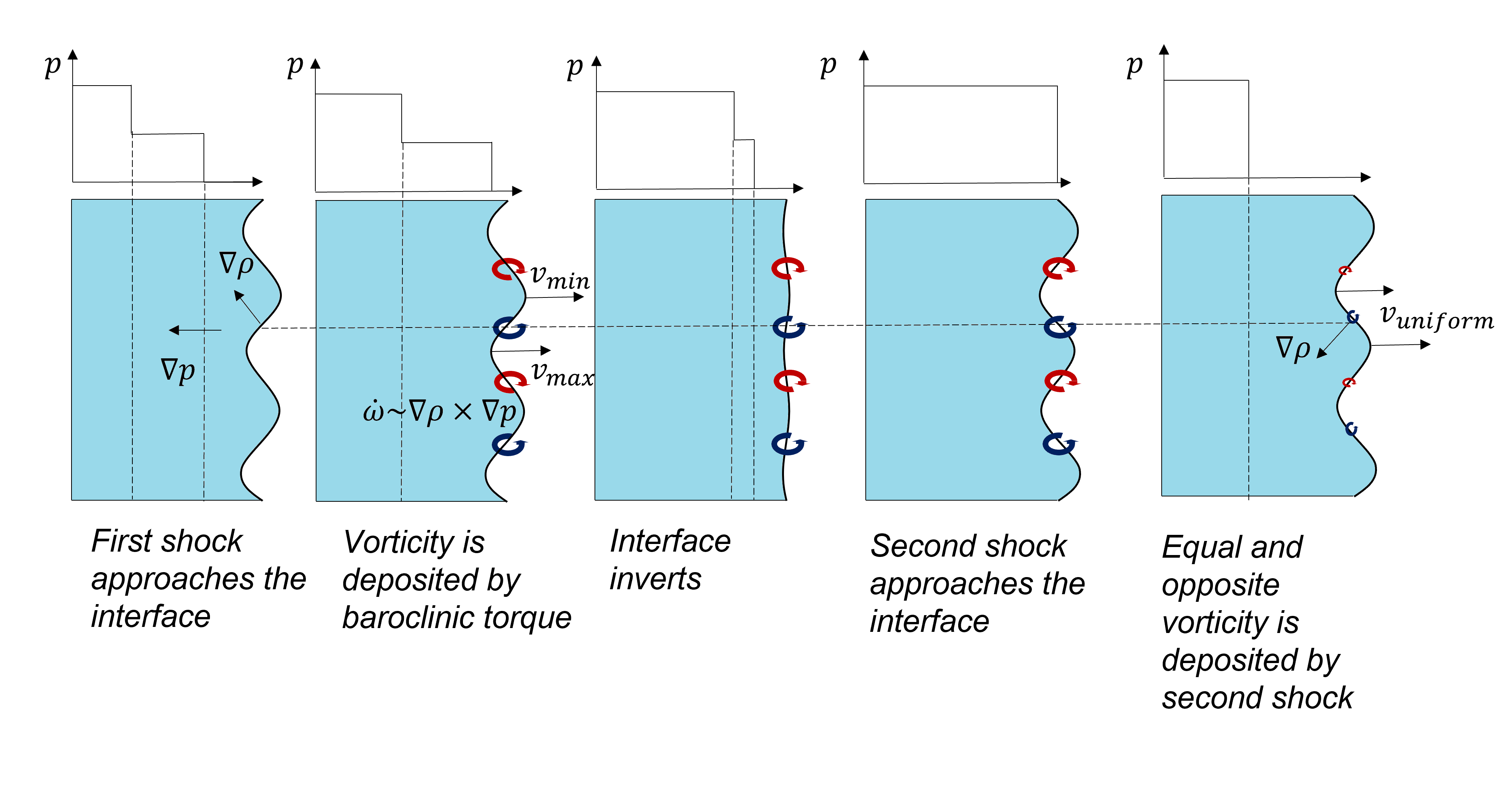
RMI has received intense study; see the reviews [7, 8] and the references therein. A productive description of RMI in terms of the vorticity field (cf. [9]) was introduced in [10, 11, 12]. See also [13]. In this conception of the instability physics, the passage of the shock through the interface deposits vorticity at the interface via the baroclinic mechanism. The variation in the sign of the vorticity arising from the non-planarity of the interface gives rise to the instability.
In this article, we advance the following conjecture: for a heavy-light interface loaded by two shocks in sequence, owing to the fact that the interface shape inverts (i.e. valleys become peaks and peaks become valleys), there will be a special time delay between the shocks such that the vorticity deposited by the second shock will be nearly equal and opposite the vorticity deposited by the first shock; thereby canceling (potentially to zero) and leaving the interface stable. The proposed RMI suppression principle which we refer to as double shock is illustrated in Fig. 1.

II A basic model
The classical paper by Richtmyer [16] modified earlier work due to Taylor [17] to derive the velocity of amplitude growth for a single sinusoidal surface perturbation of wavenumber
| (1) |
where is the jump in particle velocity arising from the shock, is the Atwood number, and is the initial amplitude.
We now suppose that the effects of two shocks in sequence may be superposed linearly giving the perturbation amplitude velocity
| (2) |
where
| (3) |
where the index denotes the first or second shock. Note the dependence on wavenumber . We observe that under a constant velocity following the first shock, the initial amplitude for the second shock will be
| (4) |
Now, we investigate whether there is a pair of shocks for which the amplitude growth is minimized. Minimizing , and solving equations (2),(3), and (4) we obtain an expression for the delay time between the two shocks as a function of the jumps in velocity
| (5) |
where is a geometric prefactor accounting for the effects of multiple wavenumbers
| (6) |
Equation (5) has the simple interpretation of the harmonic average of the particle velocity jumps with a prefactor coming solely from the Atwood number and the spectral content of the interface via . Evidently, for , this equations yields . We mention that, in the special case of a single wavenumber, and the velocity arrests completely; this phenomena was first pointed out by [18], labeled ‘freeze-out’, and a formula which is a special case of (5) was presented.
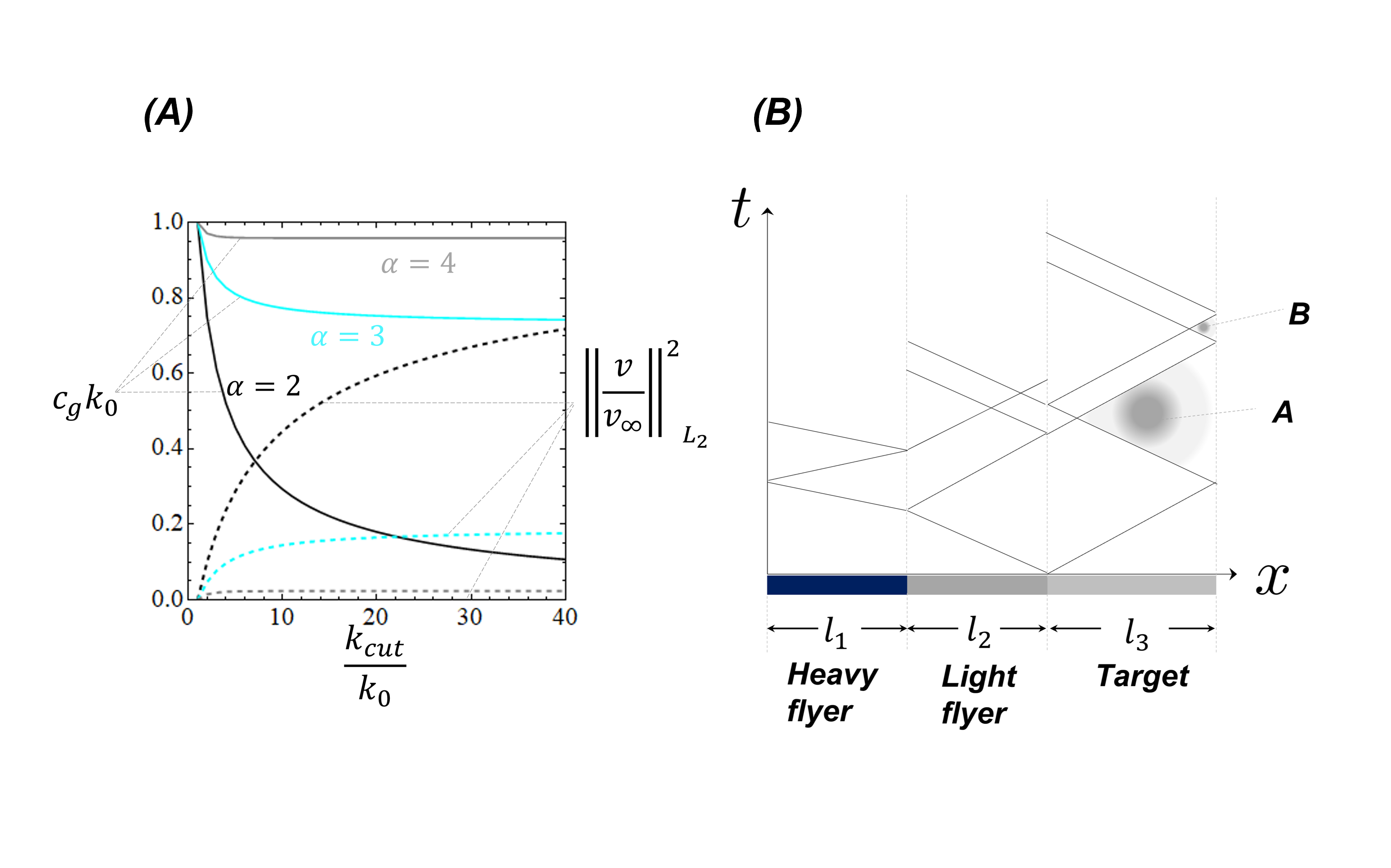
Evidently, depends on the spectral content of the initial interface via . We suppose that for and for . Taking to be a small integer and to be large provides a simple prototype for many realistic interfaces wherein the small scale features are much smoother below some lengthscale. Also, RMI effects of large wavenumbers may be regularized out by effects like strength, viscosity, or non-linearity. We show in Fig. 2(A) the geometric factor and the norm of the instability growth velocity (normalized by unmitigated jet velocity) plotted versus for . Note that we have normalized and by the smallest wavenumber . The case of is a prototype for an interface with sharp features such as a v-groove; the case of would correspond to a highly smooth interface where the spectral content decays rapidly with increasing wavenumber. Evidently, the jetting suppression is substantial particularly for not too large or for . In light of the case of , we observe that can be interpreted as the fractional reduction in delay time between the two shock waves relative to the optimal delay time for an interface with a single wave number.
To understand the shock structure, we consider the concrete case of a stepped flier. We consider the x-t diagram for the 1D setting as illustrated in Fig. 2 (B). The stepped flier consisting of heavy (navy) and light (gray) materials strikes the target (light gray). We remark that this is, in fact, quite a bit simpler than the 2D RMI picture we have thus far introduced however we can obtain a surprising amount of insight regarding the shock strengths and timing. The classical jump conditions from the balance of momentum (neglecting dissipative effects) is where is the pressure, is the density, and is the particle velocity.

For simplicity, we suppose that at the particle velocities experienced by the target and first flier, the shock speed is nearly constant. Further, we assume that the changes in density are not too large. With these assumptions, it is easy to develop explicit expressions for the particle velocity following the arrival of the first and second shock. The particle velocity of the first and second shock , respectively, are given by
| (7) |
and
| (8) |
where and are the density and shock speed of the th material indexed from left to right in Fig. 2. If the constant shock speed or small density change assumption is omitted, this still may be (analytically) solvable in certain cases, however the expressions become significantly more complex. An additional complexity here is that the topology of the intersecting shock waves in Fig. 2 may change depending on thicknesses and shock speeds; thus, the specific expression may actually change. Importantly though, the behavior of the stepped release velocity is somewhat robust with respect to these kinds of changes.
We estimate the time delay between the first and second shocks as where is the thickness of the first-shock flier. Equating this time delay and (5), we obtain an expression for the thickness which will best suppress the RMI.
We now consider scenarios in which shock-induced phase transitions can suppress RMI. In such a case, the material has multiple wave-speeds; the resulting behavior can be complex and difficult to treat analytically. To make progress, we suppose that there is a single wavespeed in both the parent and daughter materials. To have a stable multi-wave structure, we must have the condition that the lower pressure phase has a faster wave speed than the higher pressure phase: Given a certain sample size , it is easy to see that the time delay between the arrival of the first and second waves is Equating this with (5), we have a relationship between the length of the phase transition material and the wavenumber of the interface.
Similar to the preceding stepped flier discussion, we have the following simple estimate of the release velocity following the arrival of the first and second part of the shock wave: and
| (9) |
where is the phase transition pressure, , , are the shock speeds of the parent and daughter materials in the impacted material, is the shock speed in the impactor material, and is the average shock impedance. The densities (again assumed to have small variation) are in the impactor material and in the impacted material.
The pressure following passage of the second shock is
| (10) |
This is an important term to estimate because most phase transition materials have a relatively narrow pressure range in which the double shock structure holds; if the material is overdriven then the high pressure phase shock speed will overtake the low pressure shock.
An important corollary of this line of thought is that, in specific instances, a combination of experimental geometry and properties of the phase transition will lead to the self-suppression of RMI of a specific wavelength.
We remark that under very rapid compression conditions encountered in shock-compression experiments, the apparent transition pressure can vary to some degree due to effects of kinetic processes; we do not consider such effects herein but suggest that their future study in this context may also be interesting.
III Simulations and Experiments
We now present computational and experimental results which support the proposed RMI suppression strategies.
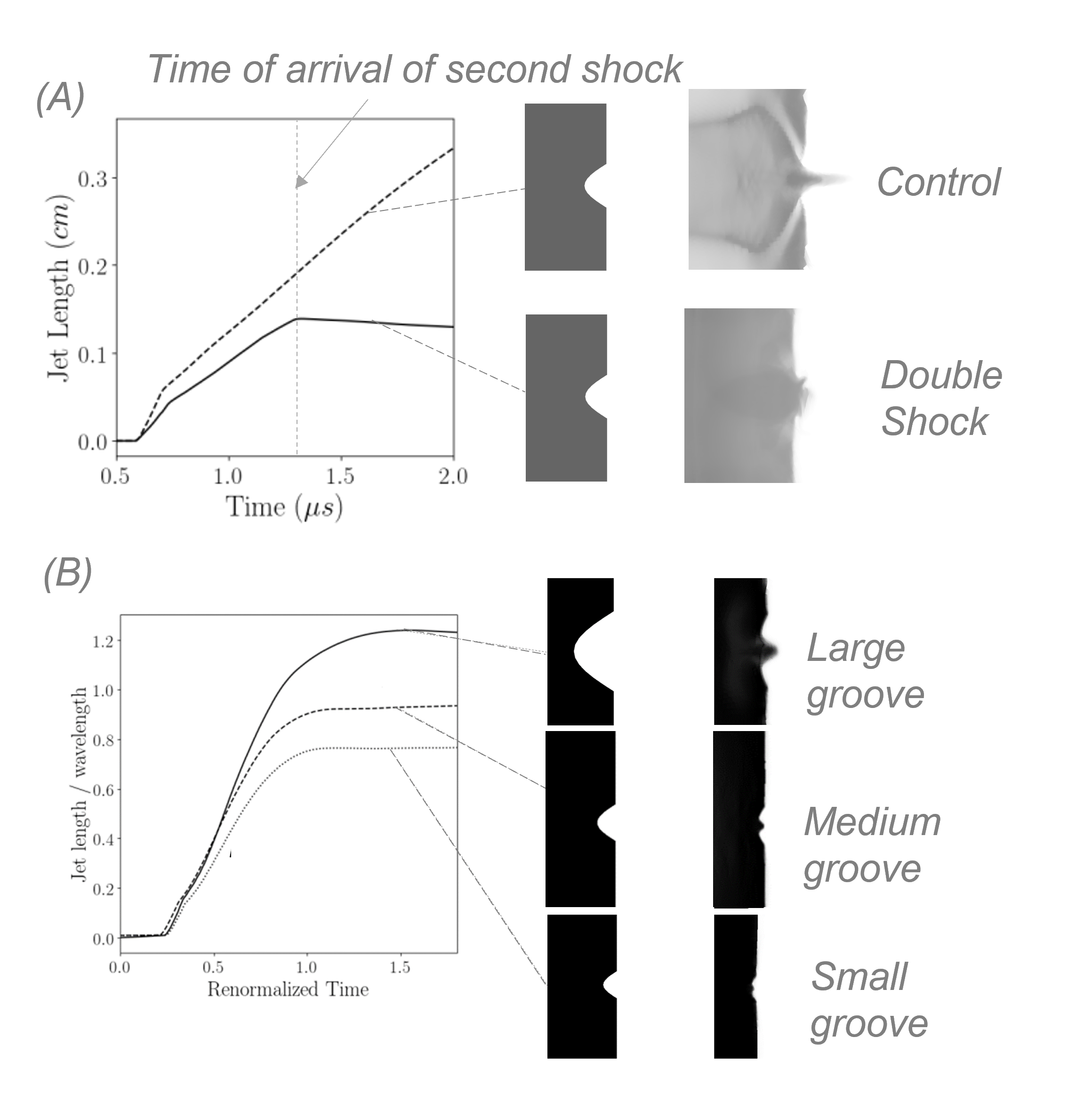
For our simulations, we use the high order production multiphysics code MARBL [20, 21, 22, 23]. We show in Fig. 3 (A) the results of two simulations wherein the jet length is computed as a function of time; the first is driven by a double shock well matched by our theory to the groove size and the second is a control case with a single shock selected to drive a free flat surface to the same particle velocity as the double shock case. Evidently, the suppression is very strong with the jet length arresting following passage of the second shock in contrast to a standard shock loading where the jet continues to grow linearly.
In Fig. 3 (B), we illustrate the variability of jetting with groove size for a shock wave passing through an iron target; iron undergoes a phase transition from (BCC) phase to (HCP) phase at a pressure of about GPa which exhibits a large volume change yielding the double shock-wave structure in this case. The analysis of instability suppression is complicated by the fact that the strength of iron is substantial; the yield strength itself will cause the jet to arrest. We must seek metrics which control for the sensitivity of arrest length to yield strength and demonstrate the sensitivity to double shock. As shown in [24], in the absence of a phase transition, one expects the product of asymptotic jet length times wave-number to exhibit this property. Thus, we plot jet length per wave length versus time and examine the variation in the asymptotic limits. We mention that the strain rate will affect the behavior of the jetting as measured by this metric; however, given the variation in groove sizes considered here, there is unlikely to be a substantial effect. The arrest length to wave length ratio decreases substantially as the wavelength is brought into alignment with the drive-timing provided by the experimental design. This demonstrates that the double shock principle, in the context of phase transitions, suppresses jetting.
We now report the results of two gas-gun experiments supporting the efficacy of the double shock principle. These experiments were conducted at Special Technologies Laboratory on their single-stage gas gun. The basic fact that we wish to exploit is that for a given two shock structure the amplitude growth rate should depend, according to our simple theory, on the wave number. Thus, we specifically design dynamic experiments with two grooves, one matching the drive and one significantly different where the jetting structure is preserved.
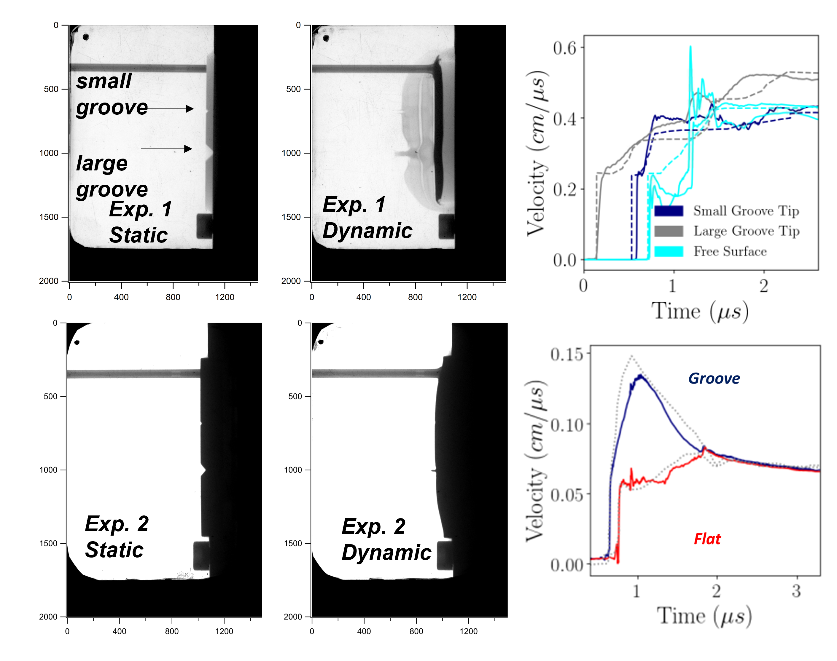
For experiment 1, we use a 39 mm diameter stepped flier (4mm thick tantalum back plate and 2.6 mm thick PMMA front) launched at 2.3 mm/. The target is a 2mm thick PMMA with a 0.6 mm deep 90 degree groove and a 2.4 mm deep 90 degree groove. Experiment 2 used a 38 mm diameter 8mm thick aluminum flier at = 1.315 mm/ striking a mm iron target with 0.6 and 2.4 mm deep 90 degree grooves. In both cases, the experiments are designed so that jetting from the smaller groove should be suppressed and jetting from the larger groove will not be well suppressed. We have used the equation of state LEOS 5060 for the PMMA target and SESAME-2140 for the iron target.
In Fig. 4, we show radiographs of the static configuration of the two experiments as well as a dynamic radiograph in late time as well as the velocimetry data for the two experiments. In the upper left of Fig. 4, the double shock experiment shows that the smaller groove (the groove well-matched to be suppressed) exhibits a strongly suppressed jet while the larger groove exhibits a standard jet. We remark that the smaller groove exhibits small secondary jets on the sides of the original grooves; we have observed that this occurs when the second shock arrives a little bit after optimal timing. In the lower left of Fig. 4, we show the late time behavior of the phase transformation experiment 2. Evidently, the jetting from the smaller groove is completely suppressed whereas the larger groove still exhibits some jetting.

On the right side of Fig. 4, we show comparisons of the experimental velocimetry traces to the simulation for experiment 1 and 2 respectively. The simulations agree well with the experimental velocimetry with very simple models and no tuning of material specific parameters. In particular, we point out that the late time velocities for the small groove and the flat surface are nearly identical while the large groove velocity remains much higher. This demonstrates suppression of jetting from the smaller groove as, in the absence of a well-tuned double shock drive, the velocities of the two groove measurements should be nearly identical.

The results presented in this letter suggest that the double shock jetting suppression principle can be successfully applied in practice. In future studies, we suggest that full-field radio-graphic measurements should be made to examine in detail complex, non-sinusoidal interfaces; we suspect that a generalization to large numbers of shocks is possible and that this approach could be applied to jetting suppression in ICF.
Acknowledgements.
This work was performed under the auspices of the U.S. Department of Energy by Lawrence Livermore National Laboratory under Contract DE-AC52-07NA27344 and was supported by the LLNL-LDRD Program under Project No. 21-SI-006. Lawrence Livermore National Security, LLNL-JRNL-846621.References
- [1] Ye Zhou et al. Rayleigh–Taylor and Richtmyer–Meshkov instabilities: A journey through scales. Physica D: Nonlinear Phenomena, 423:132838, 2021.
- [2] Garrett Birkhoff, Duncan P MacDougall, Emerson M Pugh, and Sir Geoffrey Taylor. Explosives with lined cavities. Journal of Applied Physics, 19(6):563–582, 1948.
- [3] Ye Zhou, Timothy T Clark, Daniel S Clark, S Gail Glendinning, M Aaron Skinner, Channing M Huntington, Omar A Hurricane, Andris M Dimits, and Bruce A Remington. Turbulent mixing and transition criteria of flows induced by hydrodynamic instabilities. Physics of Plasmas, 26(8):080901, 2019.
- [4] Karnig O Mikaelian. Extended model for Richtmyer–Meshkov mix. Physica D: Nonlinear Phenomena, 240(11):935–942, 2011.
- [5] Bruce A Remington et al. Rayleigh–Taylor instabilities in high-energy density settings on the national ignition facility. Proceedings of the National Academy of Sciences, 116(37):18233–18238, 2019.
- [6] Guy Dimonte, Guillermo Terrones, Frank J Cherne, and Praveen Ramaprabhu. Ejecta source model based on the nonlinear Richtmyer-Meshkov instability. Journal of Applied Physics, 113(2):024905, 2013.
- [7] Ye Zhou. Rayleigh–Taylor and Richtmyer–Meshkov instability induced flow, turbulence, and mixing. I. Physics Reports, 720-722:1–136, 2017.
- [8] Ye Zhou. Rayleigh–Taylor and Richtmyer–Meshkov instability induced flow, turbulence, and mixing. ii. Physics Reports, 723:1–160, 2017.
- [9] Alexandre J Chorin. Vorticity and turbulence. Springer Science & Business Media, 1994.
- [10] John F Hawley and Norman J Zabusky. Vortex paradigm for shock-accelerated density-stratified interfaces. Physical review letters, 63(12):1241, 1989.
- [11] JW Jacobs and JM Sheeley. Experimental study of incompressible Richtmyer–Meshkov instability. Physics of Fluids, 8(2):405–415, 1996.
- [12] Oleg A Likhachev and Jeffrey W Jacobs. A vortex model for Richtmyer–Meshkov instability accounting for finite atwood number. Physics of Fluids, 17(3):031704, 2005.
- [13] Dane M Sterbentz, Charles F Jekel, Daniel A White, Sylvie Aubry, Hector E Lorenzana, and Jonathan L Belof. Design optimization for Richtmyer–Meshkov instability suppression at shock-compressed material interfaces. Physics of Fluids, 34(8):082109, 2022.
- [14] Frank Joseph Cherne, James Edward Hammerberg, Malcolm John Andrews, V Karkhanis, and P Ramaprabhu. On shock driven jetting of liquid from non-sinusoidal surfaces into a vacuum. Journal of Applied Physics, 118(18):185901, 2015.
- [15] Karnig O Mikaelian. Richtmyer–Meshkov instability of arbitrary shapes. Physics of Fluids, 17(3):034101, 2005.
- [16] Robert D Richtmyer. Taylor instability in shock acceleration of compressible fluids. Technical report, Los Alamos Scientific Lab., N. Mex., 1954.
- [17] Geoffrey Ingram Taylor. The instability of liquid surfaces when accelerated in a direction perpendicular to their planes. i. Proceedings of the Royal Society of London. Series A. Mathematical and Physical Sciences, 201(1065):192–196, 1950.
- [18] Karnig O Mikaelian. Richtmyer-meshkov instabilities in stratified fluids. Physical Review A, 31(1):410, 1985.
- [19] Marc A Meyers. Dynamic behavior of materials. John Wiley & Sons, 1994.
- [20] Veselin A Dobrev, Tzanio V Kolev, and Robert N Rieben. High-order curvilinear finite element methods for lagrangian hydrodynamics. SIAM Journal on Scientific Computing, 34(5):B606–B641, 2012.
- [21] VA Dobrev, TE Ellis, Tz V Kolev, and RN Rieben. Curvilinear finite elements for lagrangian hydrodynamics. International Journal for Numerical Methods in Fluids, 65(11-12):1295–1310, 2011.
- [22] Robert W Anderson, Veselin A Dobrev, Tzanio V Kolev, Robert N Rieben, and Vladimir Z Tomov. High-order multi-material ALE hydrodynamics. SIAM Journal on Scientific Computing, 40(1):B32–B58, 2018.
- [23] Robert W Anderson, Veselin A Dobrev, Tz V Kolev, and Robert N Rieben. Monotonicity in high-order curvilinear finite element arbitrary lagrangian–eulerian remap. International Journal for Numerical Methods in Fluids, 77(5):249–273, 2015.
- [24] Antonio R Piriz, JJ Lopez Cela, Naeem A Tahir, and Dieter HH Hoffmann. Richtmyer-Meshkov instability in elastic-plastic media. Physical Review E, 78(5):056401, 2008.