Extended Depth-of-Field Lensless Imaging
using an Optimized Radial Mask
Abstract
The freedom of design of coded masks used by mask-based lensless cameras is an advantage these systems have when compared to lens-based ones. We leverage this freedom of design to propose a shape-preserving optimization scheme for a radial-type amplitude coded mask, used for extending the depth of field (DOF) of a lensless camera. Our goal is to identify the best parameters for the coded mask, while retaining its radial characteristics and therefore extended-DOF capabilities. We show that our optimized radial mask achieved better overall frequency response when compared to a naive implementation of a radial mask. We also quantitatively and qualitatively demonstrated the extended DOF imaging achieved by our optimized radial mask in simulations by comparing it to different non-radial coded masks. Finally, we built a prototype camera to validate the extended DOF capabilities of our coded mask in real scenarios.
Index Terms:
Lensless camera, extended depth-of-field, PSF engineeringI Introduction
Mask-based lensless cameras are formed by replacing the lenses from a traditional camera with a coded mask [1]. This replacement makes it possible to produce smaller, lighter, and cheaper cameras when compared to traditional lens-based ones. The most notable difference between these two types of cameras is that the coded mask of a lensless camera multiplexes the incoming light, mapping one point in the ambient scene to many pixels in the image sensor, thus encoding the ambient scene information in visually uninformative sensor measurements.
The sensor measurement formation process is often modeled as a two-dimensional (2D) convolution between the point spread function (PSF), which is an intensity impulse response in the spatial domain, of an optical system involving a coded mask and the incoming light from the scene [2, 3], as
| (1) |
where is a vector representing the captured sensor measurements, is the cropping function of an image defined by the effective area of the pixel of an image sensor, is a vector representing a PSF, is the 2D convolution operator, and is a vector representing the spatial light intensity of a scene. and are the pixel count of captured and scene images, respectively. We also define a matrix to simply denote the operations of 2D convolution followed by cropping. The model of Eq. (1) assumes a shift-invariant system as an approximation [4].
Ordinarily, the sensor measurements do not contain apparent visual information, and in order to reconstruct the scene information v, a reconstruction algorithm is employed. In general, the regularized error-minimization method with iterative algorithms, which is stable against noise, is often employed as the image reconstruction method. The minimization problem is defined as:
| (2) |
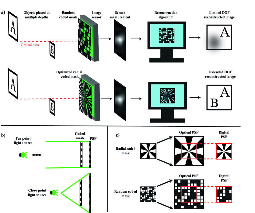
where is a vector representing a reconstructed image, is -norm of a vector, is a constant value for controlling the effectiveness of the regularization, is a regularizer, which is often a combination of linear transformation and -norm calculation. Figure 1(a) illustrates the complete pipeline of a mask-based lensless camera.
I-A Depth of Field in Lensless Imaging
Similarly to traditional lens-based cameras, mask-based lensless imagers have a limited depth of field (DOF), especially when shooting scenes that include a large distance range [9]. For a lensless system, this limitation stems from the fact that the PSF as a shadow of a coded mask is depth dependent. As illustrated in Fig. 1(b), object planes at different distances produce different PSFs. Considering this, the generalized forward model for imaging 3D scene is modeled as follows:
| (3) |
where is the distance of the object plane measured from the mask plane, and is the incoherent summation of the depth-dependent information. and are -dependent vectors of h and v, respectively, and is a -dependent matrix of A. Note that the effect of occlusion by opaque objects is ignored for simplicity. The reconstruction process using a single PSF is as follows:
| (4) |
where is the distance value to be used for reconstruction, is a matrix representing a forward operator corresponding to , and is a vector representing the reconstructed image with using . As indicated in Eq. (4), only the depth range that matches an assumed depth in the reconstruction process can be reconstructed correctly. In other words, the gap between an object’s real depth and the depth used for calibration of the PSF incurs a worse reconstruction. This limitation on the correctly-reconstructable distance range with a single reconstruction filter can be defined as a DOF of the lensless imaging system. This property is sometimes utilized in digital refocusing [5], depth-map acquisition [6], 3D imaging [3, 7, 8]; however, it is undesirable in applications such as 2D image analysis because it impairs the spatial characteristics of the image.
To address this issue, the simplest way is to set the distance between the sensor and the mask closer. This method can extend the DOF in the same way as existing lens cameras; however, the angular resolution of the imaging system is sacrificed because the angle of view is also extended at the same time. Another simple method is to measure the PSFs at multiple distances in advance, reconstruct multiple images using all of the PSFs, and merge only the areas in focus from the resulting images into a single image [10]. This method is often used for lens-based imaging as called focal-stack photography [11, 12]. However, the challenges of lensless imaging are that it requires numerous reconstruction processes and contrast calculation processes, which are computationally expensive. Furthermore, its synthesis accuracy depends on the complexity of the texture and structure of a scene. A more advanced method is to use compressive holography [13] to reconstruct a 3D tomographic image [3] and then generate an all-in-focus 2D image just by axial integration. Compressive holography reconstructs a sparse 3D tomographic image from a 2D image using a compressed sensing framework [14]. This method is very interesting as a new method for tomography, but its computational cost is high because it needs to solve an ill-posed problem. In addition, its accuracy severely depends on the sparsity of the scene.
To extend the DOF in lensless imaging while avoiding the above problems, several methods have been proposed that take advantage of the design freedom of a mask in lensless imaging. For example, Hua et al. proposed a method to realize an approximately depth-invariant PSF by sweeping the mask design during a single exposure, which, combined with post-imaging deconvolution, extends the DOF [15]. This method called SweepCam can be said to be an application of the focal-sweep method [16] to lensless cameras. This is a reasonable method to obtain an extended DOF image only with fast and stable computation, but it requires the use of a refreshable-type mask such as a liquid-crystal spatial light modulator (SLM) and sacrifices temporal resolution. As a method that can be realized with a fixed mask, Gill proposed the use of an odd-symmetry phase grating [18]. A lensless camera constructed using this mask has an extended DOF when compared to one using a normal mask [17]; However, one limitation is that the depth-invariant region of the PSF is limited to near the center of the mask, where incoming light of point-symmetric locations of the ambient scene are enforced to have their phases destructively interfere with each other at the image plane. As a result, the degree of depth-invariance is limited in principle.
On the other hand, in a past study, we proposed the radial coded mask whose PSF is the depth invariant in the whole area at the image plane [19]. A radial mask is an amplitude-transmission mask that has structure only in the rotational direction and no structure in the radial direction. Such a mask is usually used to measure optical transfer functions [2] or to generate a non-diffracting beam [20]. Figure 1(c) illustrates the concept of the depth-invariant PSF by a radial mask. From a geometry-based point of view, the change of a PSF due to a change in the object distance is manifested as a radial scaling of a PSF as also shown in Fig. 1(b). Therefore, by designing a coded mask that has no structure in the radial direction, it is possible to construct a lensless measurement system that cutoffs depth-dependent information, resulting in extended-DOF imaging using only a single deconvolution filter. In a previous study [19], this effect was verified by simulations but not by optical experiments. As for the structure of the radial mask, only one star-chart pattern with periodicity in the rotational direction was verified; however, the mask pattern should be optimized to maximize the goodness for spatial imaging while maintaining its characteristics of depth invariance.
I-B Coded Mask Optimization (Related Works)
A coded amplitude mask can be represented as a 2D tensor where the value of each element represents the light transmittance related to spatial coordinate at the mask plane. Here and are the vertical and horizontal pixel count of a spatially discretely represented mask. For the optimization of a light-transmittance pattern of a mask, i.e. the value of each element in a tensor M, Horisaki et al. [21] proposed a joint-optimization technique of the mask pattern and a reconstruction deep neural network. This work is positioned as an application of the techniques known as end-to-end optimization [22, 23] or deep optics [25, 26] to the design of lensless cameras. In the methodology, the simulation-based forward sensing model with mask variables and the reconstruction model based on a convolutional neural network (CNN) are simultaneously optimally designed by supervised training using a large amount of prepared data pairs.
In lensless imaging, optical transmittance is preferred to be designed in binary form to facilitate the implementation of the coded mask; however, using a training algorithm based on continuous optimization, the output transmittance should be a continuous value. Therefore, an additional technique is required to realize the binarization of mask variables. To address this issue, Horisaki et al. simply binarized the mask variables after training [21]. Instead of manual binarization, Bacca et al. also proposed the end-to-end optimization of the lensless imaging system, where they enforced mask parameters to be quantized, and these quantized values can be enforced to be and [24]. To the best of our knowledge, the coded mask optimization processes proposed in previous studies have generated random coded masks because they do not impose any constraints on the shape in the spatial structure of the coded masks’ parameters. When considering DOF extension, it is reasonable to constrain the mask shape to be radial, based on prior knowledge of physics.
I-C Paper Overview
In this work, we address the optimization of the radial mask for lensless imaging and the verification of the extended-DOF lensless imaging by optical experiments with a prototype. Our contributions are: (1) we proposed a radial-shape-preserving optimization scheme, in order to systematically identify the best parameters considering modulation transfer function (MTF) for a radial mask; (2) we quantitatively and qualitatively validated the extended DOF capabilities of the optimized radial coded mask through simulations; and (3) we built a prototype lensless camera and empirically validated the extended DOF of the radial coded mask.
II Radial mask optimization
In this section, we present the radial mask optimization process. We begin in Section II-A presenting a parameterization of the radial coded mask, in order to constrain the radial shape of the coded mask throughout the optimization process. Then section II-B presents our objective function and optimization scheme for the search for the best parameters of the radial mask. Finally, section II-C presents the results of the optimization process and compares the optimized mask to the original radial mask proposed in the literature.

II-A Radial Mask Parameterization
In past studies related to deep optics, the mask optimization process has been done independently for each element , which represents the light transmittance at the discretized Cartesian coordinates on the mask-plane. However, this cannot be done for this work, as it is unlikely for the radial characteristic of the mask to be preserved throughout the optimization process. In order to address this issue, we parameterize the coded mask by splitting its area into radial sections along angular coordinate, where each section originates in the center of the mask and expands to its edges. We then enforce every mask element inside the same radial section to have the same light transmittance value, as follows:
| (5) |
where is the index of the radial section, and indicates a set of spatial mask coordinates that belong to the -th radial section. In this scenario, the value of the light transmittance for the -th radial section is:
| (6) |
where represents a logistic sigmoid function, and is a single scalar value related to the light transmittance in the -th radial section. Here, the sigmoid function is employed to ensure that the values of light transmittance of the mask were in the interval . For simplicity of representation, we will not explicitly write the for the sigmoid function from this point onwards.
Here we denote a dimensionally-reduced radial-mask vector that represents all the light-transmittance parameters in a radial mask along angular axis , and represents the mapping of the light transmittance elements of the radial mask in angular coordinates to a coded mask in Cartesian coordinates. Assuming that the PSF h can be approximated as a mask vector itself, in which a diffraction effect is ignored, the PSF vector in Eq. (1) can be related to the dimensionally-reduced radial-mask vector as follows:
| (7) |
On the left side of Fig. 2 we demonstrate a common coded mask modeling approach, where the light transmittance on a position on the plane of the mask is denoted as . On the right side of Fig. 2, we show our proposed radial mask parameterization process. The number of radial sections is a hyperparameter, and it was determined manually before the optimization experiments. We empirically selected a value of for this parameter. This was decided based on the resolution used for the coded mask on the optimization experiments, which was pixels.
II-B Loss Function and Optimization Process
For optimization, we aim at improving the frequency response, i.e. MTF, of the lensless optical system. For this paper, we desire to increase MTF values of a coded mask across all frequencies. The MTF of a PSF h is defined as follows [2]:
| (8) |
where is the normalization operator with a value at zero frequency, corresponds to a 2D discrete Fourier transform, and computes the absolute values. Our proposed loss function for mask-parameter optimization is as follows:
| (9) | ||||
| (10) |
where represents the average over all elements. Note that as we aim to increase the overall MTF of the optimized coded mask, we multiply the averaged MTF by in order to use this loss in a minimization problem. The problem to be solved for obtaining the MTF-targeted optimized design of the radial mask can be simply written as:
| (11) |
where the is the vector representing the optimized radial coded mask having dimensionally-reduced optimized parameters. By solving Eq. (11) and applying the mapping function after optimization, the radial-shape-preserved MTF-targeted optimized coded mask with spatial light-transmittance parameters can be obtained.
II-C Optimization Experiment
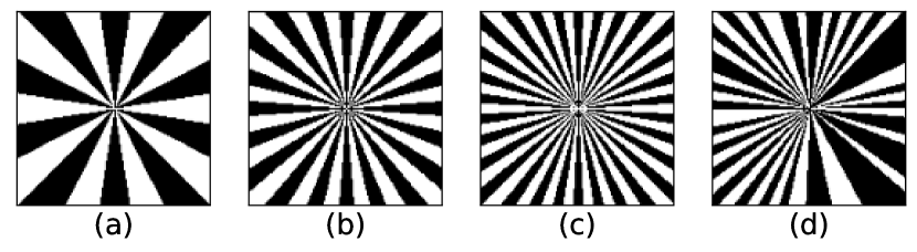
For the optimization, we used the Adam optimizer [27] with a learning rate of and optimized for epochs. The values of the vector that represents the radial mask were initialized randomly with a uniform distribution inside the interval . As baselines for this experiment, we used the widely-used star-chart-like radial mask as Ref. [19]. Such a radial mask has two important properties: (1) they are cyclical, meaning that all radial features are the same angle apart from their immediate neighbors, and (2) they are binary in terms of light transmittance. For the experiments, we compared our optimized mask against three baseline radial masks, where the first of them had 20 radial sections, the second had 40 radial sections, and the final one had 60 radial sections.
Figure 3 presents the baseline radial masks, as well as our optimized radial mask. Similarly to the baseline masks, our optimized mask also retained a binary pattern. The average light transmittance of the optimized mask is approximately 43 %, which is not distant to the 50 % of the baseline hand-crafted radial masks. Interestingly, neither the binarization nor the average light transmittance were enforced explicitly throughout training and were achieved solely by optimization through our proposed MTF-targeted loss. The main difference between the optimized mask and the baseline radial masks is that ours has an acyclic pattern for its radial sections.
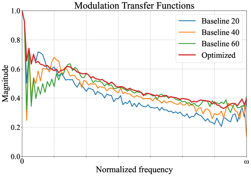
Figure 4 presents a comparison of the MTFs of the radial masks. For the baseline masks, we observed that the cyclic characteristic of the mask defines a trade-off between low-frequency and high-frequency response. That is because an increase in radial sections increases the high-frequency response of the mask, but incurs a decrease of sparsity around the area of the mask that reduces the low-frequency response. Our optimized mask, on the other hand, leveraged acyclicity to maintain areas with more and less sparsity, which improved the overall MTF values up to its Nyquist limit.
III Simulations
The primary goal of a radial mask is to extend the DOF of a lensless imaging system. So far, we have only searched for the best parameters for such a coded mask, without investigating its extended DOF properties. In this section, we determine the extended DOF of a radial mask through simulations. We also show that the reconstructed image from the lensless camera can be electronically refocused, after the image sensor measurement capture, by changing the scaling of the PSF of the coded mask.
III-A Conditions
The simulation was performed as a dual-depth object reconstruction, where we had two objects at two different distances from the lensless camera. We geometrically model the PSFs projected from both distances, and use them to generate the simulated sensor measurements for the full scene. The simulation of the sensing process was performed by calculating Eq. (3). We then reconstructed an image from the full sensor measurements by using a single PSF, that could be from either of the distances. Generally, for any type of coded mask, it is expected that the object placed at the same distance at which the PSF was calibrated should be reconstructed with a higher quality than objects at different distances from the lensless camera.
As baselines for comparison against the radial mask, we used a Fresnel zone aperture (FZA) [5, 28, 29] and a random mask [30, 31, 32] as examples. The random mask is a naive design for 2D lensless imaging that has good MTF up to cutoff frequency. The FZA is a coded mask with a structure only in the radial direction, opposite to the radial mask, and is suitable for digital refocusing applications.
For the lensless image reconstruction, we used two algorithms, namely the alternating direction method of multipliers (ADMM) method [33], and the untrained deep network (UDN) method [34]. Both methods are based on the iterative error-minimization algorithm involving regularization. For the regularization, the ADMM uses the minimization of 2D total variation (TV) [35] of a reconstructed image, while the UDN implements it by an untrained generative deep neural network, i.e., employment of deep image prior [36]. Compared to learning-based methods [37, 38, 39, 40], the results can be explainable and their precision is not restricted to a domain of learning.
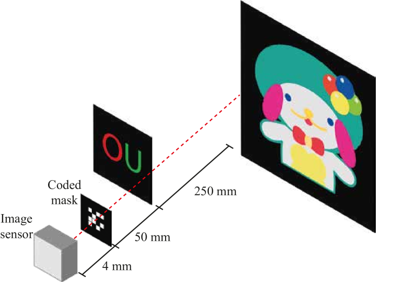
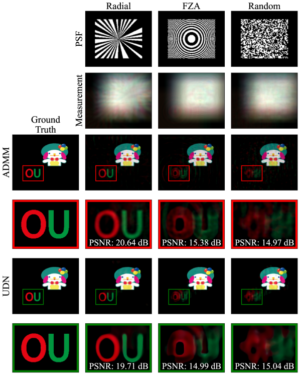
Figure 5 shows the simulated experimental setup. It involves a planar plush toy and a planar OU pattern positioned and away from the coded mask, respectively. The axial interval between the mask and an image sensor was set to . Figure 6 presents the mask patterns used for simulations, corresponding captured images, and reconstruction results with the ADMM and UDN algorithms using the PSF calibrated for a distance of . We set the size of the RGB captured measurements, simulated PSFs, and reconstructed images to pixels. In simulations, the noise was ignored to analyze the upper limit of the effect of the proposed methodology; however, a noise analysis can be drawn from the prototype camera experiments. The coded masks used in the simulations are the same ones that were used for the prototype camera experiment. In the reconstruction process, we used 150,000 iterations for the UDN algorithm and 100 iterations per channel for the ADMM algorithm. The optimization code was implemented in Pytorch with a computational environment including a GPU (GeForce 3090 by NVIDIA), 32 GiB RAM, and a 10-core CPU (i9-10900K by Intel).
III-B Reconstruction Results
We limited the effective area of the mask to approximately in the central region for increasing the stability of reconstruction [3], and the remaining perimeter of the mask was light-shielded. From the reconstruction results of Fig. 6, we observed that the plush toy was correctly reconstructed by all three types of coded masks. This was expected, as the PSF used for reconstruction was the one calibrated for the same distance as the plush-toy distance. The OU pattern, however, was closer to the lensless system than the calibrated PSF and was only reconstructed properly by the radial mask. Additionally, we note that the peak signal-to-noise ratio (PSNR) of the radial-mask reconstruction was significantly higher than that of the FZA and random coded masks. Table I(b)(a) presents a quantitative analysis of the OU pattern reconstruction between the three types of coded masks shown in Fig. 6. We note that the radial mask achieves the best reconstruction of the OU pattern in all metrics including SSIM [41] and LPIPS [42].

| ADMM | UDN | |||||
|---|---|---|---|---|---|---|
| PSNR (↑) | SSIM (↑) | LPIPS (↓) | PSNR (↑) | SSIM (↑) | LPIPS (↓) | |
| Radial | 20.64 | 0.6151 | 0.2290 | 19.71 | 0.6700 | 0.1451 |
| FZA | 15.38 | 0.4536 | 0.4285 | 14.99 | 0.5300 | 0.3876 |
| Random | 14.97 | 0.4862 | 0.6189 | 15.04 | 0.5111 | 0.5493 |
| Radial | FZA | Random | |
|---|---|---|---|
| MAE |
III-C Refocusing Ability
Additionally, we present in Fig. 7 the refocus of the reconstructed image after sensor measurements capture. We show that by changing the scaling of the PSF, it is possible to focus on either the closer object, or the farther object in the simulated scene. We note, however, that our optimized radial mask is capable of reconstructing both objects independently of the scaling used for the PSF. Table I(b)(b) presents a quantitative comparison between far-focus and close-focus PSFs for the three types of coded masks presented in Fig. 7. We note that the radial mask presents a lower mean absolute error (MAE) between far and close-focus PSFs, when compared to FZA and random masks. This justifies why the reconstruction algorithm is capable of reconstructing both objects successfully using either of the calibrated radial PSFs, which is not the case for the other types of coded masks.
IV Optical Experiments with a Prototype Camera
IV-A Setup
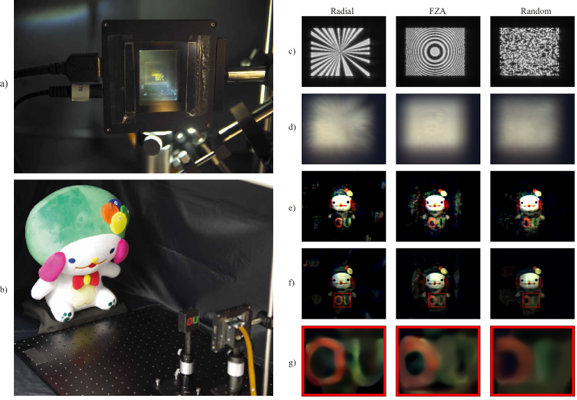
Finally, we create a prototype lensless camera, to validate the extended DOF of the radial mask in the real world. Similarly to the simulation, this experiment consists of reconstructing two objects at different distances from the lensless imager, but in a real scenario. Figure 8(a) shows a frontal view of the prototype lensless camera, which consists of an axial stack of a coded mask and an image sensor. The coded mask was implemented by a transmissive liquid-crystal SLM (LC2012 by HOLOEYE Photonics) and two polarization plates in the crossed Nicols configuration. All coded masks to be tested are originally binary, therefore, the light transmittance of the SLM was designed as binary, and central pixels with pitches were used for implementing the coded masks. The fill factor of the SLM was . Approximately behind the modulation plane of the SLM, we placed a color CMOS image sensor (BFS-U3-51S5C-BD by Teledyne FLIR) whose pixel count was with pitches. In the experiment, -bit RGB captured images were readout and they were downsampled to pixels for reconstruction. As well as simulations, the periphery of the mask was shielded for increasing reconstruction stability where the effective area of the mask was approximately . The center of the effective area of the SLM and the image sensor were aligned by translation stages, and the planes of the two elements were adjusted to be parallel.
Figure 8(b) shows the experimental setup including the camera and targets to be imaged. In front of a lensless camera prototype, we placed two diffuse reflective objects: a stuffed toy known as SANKEN, which is one of the symbols of Osaka University (SANKEN plush toy), and a black tape with the letters ’OU’ printed on it (OU letters). The SANKEN toy and the OU letters were placed at approximately and centimeters (cm) away from the mask, respectively. These objects were illuminated by a white LED light Installed around above the camera.
IV-B PSF Calibration
The top right in Fig. 8 shows the calibrated PSFs. The PSFs were calibrated by experimental capture of a spherical wave emitted from a light point source placed away from the camera, which was the same distance as the SANKEN toy. The light-point source we used was composed of a semiconductor laser whose central wavelength was 532 nm (Stradus 532 by Vortran Laser Technology), followed by a spatial filter (SFB-16DMRO-OBL40-25 by SIGMA KOKI) which contained a pinhole whose diameter was . The combination of the laser with the spatial filter generated a spherical wave.
IV-C Experiments
The second row of the right in Fig. 8 shows the captured lensless measurements. Although the captured image cannot be recognized by human vision, the encoded images of objects at multiple distances were multiply recorded based on the physical model in Eq. (3). The captured image also contains color information. Note that each coded image of Fig. 8 was normalized for visualization.
The PSF was calibrated by the point light source positioned away from the coded mask. Therefore, it was expected for the object at a distance to be correctly reconstructed for all three types of coded masks. The OU pattern object, however, was placed away from the coded mask and was expected to be more challenging to be reconstructed properly. The coded masks and reconstruction algorithms used here were the same as those used in the simulations. The reconstructions for the radial, FZA, and random coded masks using the ADMM and UDN algorithms are shown in the third and fourth rows of the right part of Fig. 8, respectively. The bottom row presents the close-up view of the OU letters reconstructed by the UDN algorithm. As expected, the plush toy was correctly reconstructed in all experiments, independently of the type of coded mask or the reconstruction algorithm employed. We note, however, that reconstruction with resolving the two letters on the OU pattern was only successful by the radial coded mask, due to its robustness against the scaling of its PSF, i.e., extended DOF characteristics. The reconstructions using the FZA and random masks, on the other hand, were blurred and the two letters seemed to mix together.
V Conclusion
We proposed a radial-shape-preserving optimization scheme for coded masks, which can be used to systematically create radial masks with better overall frequency response when compared to the conventional radial masks. We showed through simulations that the optimized radial mask was capable of extending the effective DOF of a lensless camera when compared to other types of coded masks. We also built a prototype lensless camera and empirically validated the extended DOF capabilities of the radial mask in real scenarios.
V-A Limitations
Theoretically, the PSF of a radial-shaped coded mask is depth-independent, meaning that it is not affected by radial scaling as illustrated in Figure 1(c). That would be the case if the effective area of the coded mask were larger than that of an image sensor. In practice, however, the coded pattern is often smaller than the effective pixel area of an image sensor, with the edges of the coded pattern being light-shielded. This shielding is necessary when the forward model is approximately described by a convolution because it suppresses the amount of information interception by the cropping function in sensing. In this case, even though the reconstruction processing works well and the coded pattern is depth-independent, the complete PSF formed by the coded pattern and its edge is actually depth dependent to some extent. In future work, we will address this issue by non-convolutional, e.g. matricial, modeling of the forward problem, and/or the application of more robust compressive reconstruction algorithms such as the primal-dual splitting method, and deep-unrolling method.
In addition, this work only addressed the amplitude-modulation-type coded mask. When compared to phase masks, one limitation of amplitude masks is the lower light-use efficiency and optical cut-off frequency. In theory, however, the essence of this work is that the PSF is radially-shaped, and the mask implementation method and its design should be free. Therefore, it is necessary for future works to develop masks for extended-DOF lensless imaging using phase masks with high light-utilization efficiency.
References
- [1] V. Boominathan, J. T. Robinson, L. Waller, and A. Veeraraghavan, “Recent advances in lensless imaging,” Optica, vol. 9, no. 1, pp. 1–16, Jan. 2022.
- [2] J. W. Goodman, Introduction to Fourier Optics. McGraw-Hill, 1996.
- [3] N. Antipa, G. Kuo, R. Heckel, B. Mildenhall, E. Bostan, R. Ng, and L. Waller, “DiffuserCam: lensless single-exposure 3D imaging,” Optica, vol. 5, no. 1, pp. 1–9, 2018.
- [4] L. Mertz and N. O. Young, “Fresnel transformation of images (Fresnel coding and decoding of images),” in Optical Instruments and Techinques, 1962, p. 305.
- [5] T. Shimano, Y. Nakamura, K. Tajima, M. Sao, and T. Hoshizawa, “Lensless light-field imaging with Fresnel zone aperture: quasi-coherent coding,” Appl. Opt., vol. 57, no. 11, pp. 2841–2850, 2018.
- [6] Y. Zheng and M. Salman Asif, “Joint Image and Depth Estimation With Mask-Based Lensless Cameras,” IEEE Trans. Comput. Imaging, vol. 6, pp. 1167–1178, 2020.
- [7] J. K. Adams, V. Boominathan, B. W. Avants, D. G. Vercosa, F. Ye, R. G. Baraniuk, J. T. Robinson, and A. Veeraraghavan, “Single-frame 3D fluorescence microscopy with ultraminiature lensless FlatScope,” Sci. Adv., vol. 3, no. 12, pp. 1–10, 2017.
- [8] F. Tian and W. Yang, “Learned lensless 3D camera,” Opt. Express, vol. 30, no. 19, pp. 34479–34496, Sep. 2022.
- [9] J. Tan, V. Boominathan, A. Veeraraghavan, and R. Baraniuk, “Flat focus: depth of field analysis for the FlatCam lensless imaging system,” in 2017 IEEE International Conference on Acoustics, Speech and Signal Processing (ICASSP), 2017, pp. 6473–6477.
- [10] Y. Hua, M. S. Asif, and A. C. Sankaranarayanan, “Spatial and axial resolution limits for mask-based lensless cameras,” Opt. Express, vol. 31, no. 2, pp. 2538–2550, Jan. 2023.
- [11] K. N. Kutulakos and S. W. Hasinoff, “Focal Stack Photography: High-Performance Photography with a Conventional Camera,” in International Conference on Machine Vision and Applications, 2009, pp. 332–337.
- [12] Z. Huang, J. A. Fessler, and T. B. Norris, “Focal stack camera: depth estimation performance comparison and design exploration,” Opt. Contin., vol. 1, no. 9, pp. 2030–2042, Sep. 2022.
- [13] D. J. Brady, K. Choi, D. L. Marks, R. Horisaki, and S. Lim, “Compressive Holography,” Opt. Express, vol. 17, no. 15, p. 13040, Jul. 2009.
- [14] E. J. Candes and M. Wakin, “An Introduction To Compressive Sampling,” IEEE Signal Process. Mag., vol. 25, no. 2, pp. 21–30, Mar. 2008.
- [15] Y. Hua, S. Nakamura, M. S. Asif, and A. C. Sankaranarayanan, “SweepCam - Depth-Aware Lensless Imaging Using Programmable Masks,” IEEE Trans. Pattern Anal. Mach. Intell., vol. 42, no. 7, pp. 1606–1617, 2020.
- [16] S. Kuthirummal, H. Nagahara, C. Zhou, and S. K. Nayar, “Flexible Depth of Field Photography,” IEEE Trans. Pattern Anal. Mach. Intell., vol. 33, no. 1, pp. 58–71, Jan. 2011.
- [17] P. R. Gill and D. G. Stork, “Lensless Ultra-Miniature Imagers Using Odd-Symmetry Spiral Phase Gratings,” in Imaging and Applied Optics, 2013, p. CW4C.3.
- [18] P. R. Gill, “Odd-symmetry phase gratings produce optical nulls uniquely insensitive to wavelength and depth,” Opt. Lett., vol. 38, no. 12, pp. 2074–2076, 2013.
- [19] T. Nakamura, S. Igarashi, S. Torashima, and M. Yamaguchi, ”Extended depth-of-field lensless camera using a radial amplitude mask.” in Imaging and Applied Optics Congress, OSA Technical Digest, Optica Publishing Group, 2020.
- [20] S. Rasouli, A. M. Khazaei, and D. Hebri, “Talbot carpet at the transverse plane produced in the diffraction of plane wave from amplitude radial gratings,” J. Opt. Soc. Am. A, vol. 35, no. 1, pp. 55–64, 2018.
- [21] R. Horisaki, Y. Okamoto, and J. Tanida, “Deeply coded aperture for lensless imaging,” Opt. Lett., vol. 45, no. 11, pp. 3131–3134, 2020.
- [22] V. Sitzmann, S. Diamond, Y. Peng, X. Dun, S. Boyd, W. Heidrich, F. Heide, and G. Wetzstein., “End-to-end optimization of optics and image processing for achromatic extended depth of field and super-resolution imaging,” ACM Trans. Graph., vol. 37, no. 4, pp. 1–13, 2018.
- [23] H. Zhou, H. Feng, W. Xu, Z. Xu, Q. Li, and Y. Chen, “Deep denoiser prior based deep analytic network for lensless image restoration,” Opt. Express, vol. 29, no. 17, pp. 27237–27253, Aug. 2021.
- [24] J. Bacca, T. Gelvez-Barrera and H. Arguello, ”Deep Coded Aperture Design: An End-to-End Approach for Computational Imaging Tasks,” in IEEE Trans. Comput. Imaging, vol. 7, pp. 1148–1160, 2021.
- [25] H. Haim, S. Elmalem, R. Giryes, A. M. Bronstein, and E. Marom, “Depth Estimation From a Single Image Using Deep Learned Phase Coded Mask,” IEEE Trans. Comput. Imaging, vol. 4, no. 3, pp. 298–310, 2018.
- [26] J. Chang, V. Sitzmann, X. Dun, W. Heidrich, and G. Wetzstein, “Hybrid optical-electronic convolutional neural networks with optimized diffractive optics for image classification,” Sci. Rep., vol. 8, no. 1, p. 12324, 2018.
- [27] D. P. Kingma, J. Ba, ”Adam: A Method for Stochastic Optimization,” in 3rd International Conference on Learning Representations (ICLR), 2015.
- [28] J. Wu, H. Zhang, W. Zhang, G. Jin, L. Cao, and G. Barbastathis, “Single-shot lensless imaging with fresnel zone aperture and incoherent illumination,” Light Sci. Appl., vol. 9, no. 1, p. 53, Apr. 2020.
- [29] T. Nakamura, T. Watanabe, S. Igarashi, X. Chen, K. Tajima, K. Yamaguchi, T. Shimano, and M. Yamaguchi, “Superresolved image reconstruction in FZA lensless camera by color-channel synthesis,” Opt. Express, vol. 28, no. 26, pp. 39137–39155, Dec. 2020.
- [30] T. Nakamura, K. Kagawa, S. Torashima, and M. Yamaguchi, “Super Field-of-View Lensless Camera by Coded Image Sensors,” Sensors, vol. 19, no. 6, p. 1329, 2019.
- [31] Y. Zheng, Y. Hua, A. C. Sankaranarayanan, and M. S. Asif, “A Simple Framework for 3D Lensless Imaging with Programmable Masks,” in 2021 IEEE/CVF International Conference on Computer Vision (ICCV), Oct. 2021, no. Iccv, pp. 2583–2592.
- [32] V. Boominathan, J. K. Adams, J. T. Robinson, and A. Veeraraghavan, “PhlatCam: Designed Phase-Mask Based Thin Lensless Camera,” IEEE Trans. Pattern Anal. Mach. Intell., vol. 42, no. 7, pp. 1618–1629, 2020.
- [33] S. Boyd, N. Parikh, E. Chu, B. Peleato, and J. Eckstein, ”Distributed optimization and statistical learning via the alternating direction method of multipliers,” Foundations and Trends in Machine Learning, Vol 3, pp 1-122, 2011.
- [34] K. Monakhova, V. Tran, G. Kuo, and L. Waller, ”Untrained networks for compressive lensless photography,” Opt. Express 29, 20913-20929, 2021.
- [35] L. I. Rubin, S. Osher, and E. Fatemi, “Nonlinear total variation based noise removal algorithms,” Phys. D, vol. 60, pp. 259–268, 1992.
- [36] D. Ulyanov, A. Vedaldi, and V. Lempitsky, “Deep Image Prior,” Int. J. Comput. Vis., vol. 128, no. 7, pp. 1867–1888, 2020.
- [37] A. Sinha, J. Lee, S. Li, and G. Barbastathis, “Lensless computational imaging through deep learning,” Optica, vol. 4, no. 9, pp. 1117–1125, 2017.
- [38] K. Monakhova, J. Yurtsever, G. Kuo, N. Antipa, K. Yanny, and L. Waller, “Learned reconstructions for practical mask-based lensless imaging,” Opt. Express, vol. 27, no. 20, pp. 28075–28090, 2019.
- [39] G. Barbastathis, A. Ozcan, and G. Situ, “On the use of deep learning for computational imaging,” Optica, vol. 6, no. 8, pp. 921–943, 2019.
- [40] J. Rego, H. Chen, S. Li, J. Gu, and S. Jayasuriya, “Deep Camera Obscura: An Image Restoration Pipeline for Pinhole Photography,” Opt. Express, vol. 30, no. 15, pp. 27214–27235, 2022.
- [41] Z. Wang, A. C. Bovik, H. R. Sheikh, and E. P. Simoncelli, “Image Quality Assessment: From Error Visibility to Structural Similarity,” IEEE Trans. Image Process., vol. 13, no. 4, pp. 600–612, Apr. 2004.
- [42] R. Zhang, P. Isola, A. A. Efros, E. Shechtman, and O. Wang, “The Unreasonable Effectiveness of Deep Features as a Perceptual Metric,” in 2018 IEEE/CVF Conference on Computer Vision and Pattern Recognition, Jun. 2018, no. 1, pp. 586–595.
![[Uncaptioned image]](/html/2303.11554/assets/figs/photo_vieira.jpg) |
José Reinaldo Cunha Santos A. V. Silva Neto received the B.S. in engineering and M.S. in computer science from the University of Brasilia, in 2019 and 2021 respectively. Currently, he is a PhD candidate on the computer science department of Osaka University. His research interests include computational photography, with a preference for lensless imaging, and deep learning techniques applied to computer vision. |
![[Uncaptioned image]](/html/2303.11554/assets/x9.png) |
Tomoya Nakamura received the Ph.D. degree from Osaka University, in 2015. He is currently an Associate Professor with SANKEN, Osaka University. His research interests include computational imaging, computational photography, and applied optics. He is a member of the Optica and the IPSJ. He received several honors and awards, including the International Display Workshops (IDW 2017), the Best Paper Award, and the 4th International Workshop on Image Sensor and Systems (IWISS 2018), the Open Poster Session Award 1st Place. |
![[Uncaptioned image]](/html/2303.11554/assets/figs/photo_makihara.jpg) |
Yasushi Makihara received the B.S., M.S., and Ph.D. degrees in engineering from Osaka University, in 2001, 2002, and 2005, respectively. He is currently a Professor with SANKEN (The Institute of Scientific and Industrial Research), Osaka University. His research interests include computer vision, pattern recognition, and image processing, including gait recognition, pedestrian detection, morphing, and temporal superresolution. He is a member of the IPSJ, the IEICE, the RSJ, and the JSME. He received several honors and awards, including the 2nd International Workshop on Biometrics and Forensics (IWBF 2014), the IAPR Best Paper Award, the 9th IAPR International Conference on Biometrics (ICB 2016), and the Honorable Mention Paper Award. He was the Program Co-Chair of the 4th Asian Conference on Pattern Recognition (ACPR 2017). |
![[Uncaptioned image]](/html/2303.11554/assets/figs/photo_yagi.jpg) |
Yasushi Yagi (Senior Member, IEEE) received the Ph.D. degree from Osaka University, in 1991. In 1985, he joined the Product Development Laboratory, Mitsubishi Electric Corporation, where he was involved in robotics and inspections. He became a Research Associate, in 1990, a Lecturer, in 1993, an Associate Professor, in 1996, and a Professor, in 2003, with Osaka University, where he was the Director of SANKEN (The Institute of Scientific and Industrial Research), from 2012 to 2015. He was the Executive Vice President of Osaka University, from 2015 to 2019. His research interests include computer vision, pattern recognition, biometrics, human sensing, medical engineering, and robotics. He is a fellow of the IPSJ and a member of the IEICE and the RSJ. He is a member of the Editorial Board of the International Journal of Computer Vision. He is the Vice President of the Asian Federation of Computer Vision Societies. He was awarded the ACM VRST2003 Honorable Mention Award, the IEEE ROBIO2006 Finalist of the T. J. Tan Best Paper in Robotics, the IEEE ICRA2008 Finalist for the Best Vision Paper, the PSIVT2010 Best Paper Award, the MIRU2008 Nagao Award, the IEEE ICCP2013 Honorable Mention Award, the MVA2013 Best Poster Award, the IWBF2014 IAPR Best Paper Award, and the IPSJ Transactions on Computer Vision and Applications Outstanding Paper Award (2011 and 2013). International conferences for which he has served as the Chair include ROBIO2006 (PC), ACCV (2007PC and 2009GC), PSVIT2009 (FC), and ACPR (2011PC, 2013GC, 2021GC, and 2023GC). He has al so served as an Editor for the IEEE ICRA Conference Editorial Board (2008 and 2011). He was the Editor-in-Chief of the IPSJ Transactions on Computer Vision and Applications. |