Rotating Objects via In-Hand Pivoting using
Vision, Force and Touch
Abstract
We propose a robotic manipulation method that can pivot objects on a surface using vision, wrist force and tactile sensing. We aim to control the rotation of an object around the grip point of a parallel gripper by allowing rotational slip, while maintaining a desired wrist force profile. Our approach runs an end-effector position controller and a gripper width controller concurrently in a closed loop. The position controller maintains a desired force using vision and wrist force. The gripper controller uses tactile sensing to keep the grip firm enough to prevent translational slip, but loose enough to allow rotational slip. Our sensor-based control approach relies on matching a desired force profile derived from object dimensions and weight, as well as vision-based monitoring of the object pose. The gripper controller uses tactile sensors to detect and prevent translational slip by tightening the grip when needed. Experimental results where the robot was tasked with rotating cuboid objects 90 degrees show that the multi-modal pivoting approach was able to rotate the objects without causing lift or translational slip, and was more energy-efficient compared to using a single sensor modality or pick-and-place.
I Introduction
Robotic manipulation can be prehensile or non-prehensile. Prehensile manipulation involves capturing the object (e.g., via grasping) and requires achieving stable control over the grasped object. During object transport, prehensile manipulation requires the object to be lifted and held stably in the grasp. Non-prehensile manipulation, on the other hand, is a type of manipulation where objects are manipulated without grasping them. Non-prehensile manipulation allows a robot to perform a wider range of tasks than prehensile manipulation and can be more energy-efficient than prehensile manipulation because it does not require the robot to use as much force to move the object. In this study, we focus on performing pivoting actions on objects grasped by a parallel gripper. As shown in Fig.1, this action takes an interesting middle ground between non-prehensile and prehensile manipulation. On the one hand, it requires the object to be grasped and gives the robot more stable control over the pose of the object. On the other hand, the action does not require the target object to be lifted, requiring much less effort than performing a full pick and place [1]. With less force exerted, this approach allows the manipulation of objects heavier than the maximum payload of a robot [2].
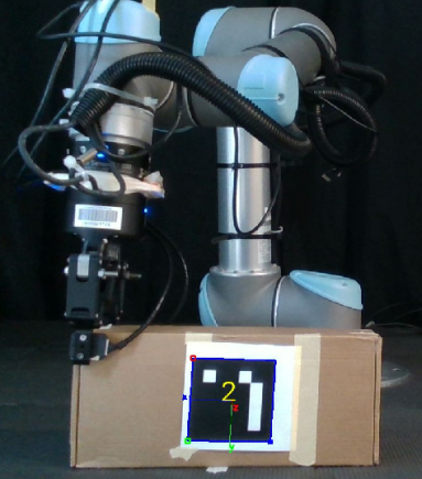
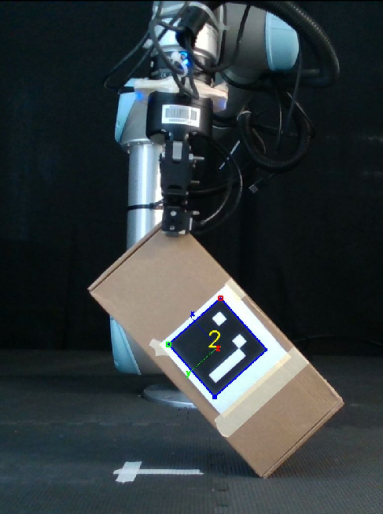
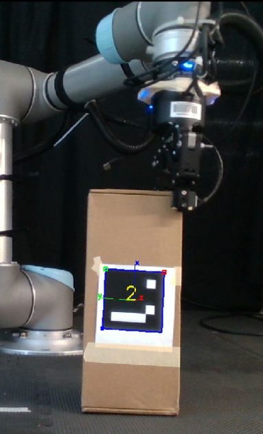
This study investigates reorienting an object grasped by a parallel gripper using pivoting actions. To achieve in-hand manipulation with a simple parallel gripper with no dexterous capabilities, we make use of extrinsic environmental factors [3]. Specifically, once the object is grasped, gravity is used to induce slip and rotate the object in-hand when lifting the gripper. Meanwhile, friction with the surface provides an opposing force to fully pivot the object. Thus, to allow this friction, the object must also be kept in contact with the surface during the motion.
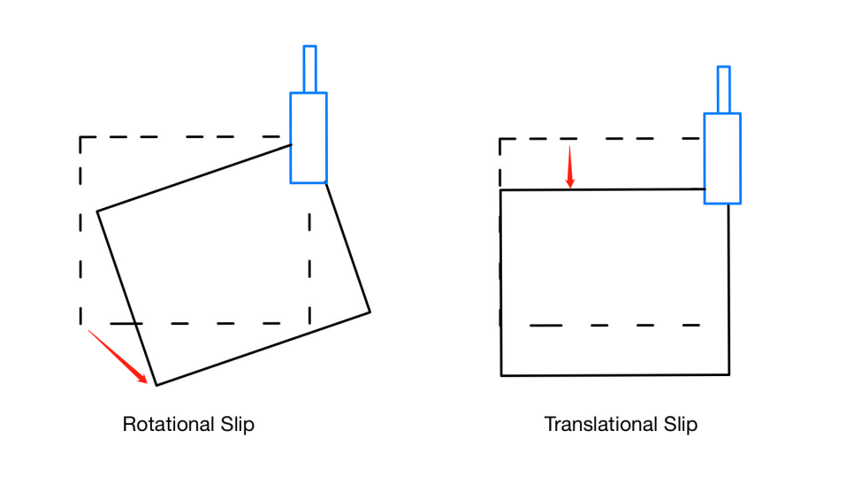
As shown in Fig.1, to avoid the need to turn the gripper along with the box, which introduces additional kinematic constraints on the robot, the box is allowed to rotate around the grasp point. Enabling slip in the grasp of the object is a non-trivial problem. To achieve the desired slip, the appropriate gripper force or finger width needs to be chosen in accordance to the properties of the object. To gain better insight into the forces that can induce in-hand slip, we follow other works on slip detection [4, 5, 6] in differentiating slip into two types, rotational slip and translational or linear slip. As shown in Fig.2, in rotational slip, the object is allowed to rotate while remaining grasped, with its centre of rotation at the grasp point and remaining in place as the object moves. Translational or linear slip involves the object moving away from the original grasping point. These two types of slip can occur on their own or simultaneously. For an in-hand pivoting task, the goal is to avoid translational slip, while allowing rotational slip [7].
Similarly, the trajectory of the pivoting motion also needs to be adjusted to ensure the object remains in contact with the surface. Visual information may be used to determine the object’s pose, but contact with the surface may be challenging to estimate visually. On the other hand, force data can be used to derive whether the object is lifted by the robot, but otherwise would provide little information about the object’s pose.
We propose using multi-modal sensing in closed-loop control that can adjust both the robot arm trajectory and the gripper width to complete a pivoting action. The object state
will be continuously detected through force/torque data at the parallel fingers and wrist of the gripper, as well as visual information from an RGB-D camera. Pivoting of the grasped object will then be achieved through motion planning with the arm’s end-effector coupled with a position controller, while slip will be managed by adjusting the gripper width. Overall, the main contributions of this study are:
-
•
A vision and force-based position controller for the arm trajectory that integrates an analytical force profile and object pose information
-
•
A tactile sensor-based gripper width controller for parallel grippers that tightens based on detected slip
-
•
Experiments on a real robot that validate the effectiveness of multi-modal sensing for the pivoting task
II Related Works
Pivoting provides an alternative to pick-and-place methods for reorienting the pose of an object. A significant advantage of the pivoting motion is the ability to extend manipulation to reorienting heavy, large and/or long objects [8, 9, 10, 11] that cannot be picked up by robot. Previous works focus on in-hand pivoting where the object is held in air [7, 12] while others target pivoting using a surface to support the motion [8, 9, 10, 11]. For our purposes, we will focus on pivoting with the assistance of a surface.
To achieve pivoting, planning based approaches are frequently adopted [8, 9, 11, 13, 14]. Closed loop control is also common, such as using impedance and admittance control to optimise a force planner [10]. Machine learning methods are also used to control robot behaviour using complex input data [7, 12]. Our solution aims at a learning-free control algorithm for the gripper width as well as end effector position during a pre-planned pivoting motion.
II-A Contact Control
Adopting a purely open loop approach can often be limiting as the robot only considers the environment’s initial states and is unaware how its interactions influence them [15]. In terms of the pivoting action, the motion of the robot needs to be updated based on the object’s contact with the surface to induce friction and complete a full pivot.
For similar tasks, force and torque data is often used to estimate the state of the robot held object’s contact with its surroundings. Ma et al. detected extrinsic contact between a grasped object and the environment using tactile sensors mounted to a parallel gripper [16]. Molchanov et al. used a data-driven approach, training machine learning models with tactile data to perform regression and classification for the presence and location of contact between object and environment [17]. Doshi et al. used force/torque data to estimate how a wrench applied to an object would affect its motion using a contact model [18]. Hogan et al. used high-resolution tactile sensors to localise the pose of held object and estimate contact and slip status. Both [18] and [19] also developed and experimentally tested closed loop controllers for manipulation.
Vision inputs are also used to compliment tactile data. Yu et al. trained a model with visually detected pose estimates for an object of known geometry, as well as tactile data from a wrist force/torque sensor and robot encoders [20]. The model was used to detect the contact arrangement of a held object, and achieved more accurate estimates than using vision alone.
We take a multi-modal approach to maintain extrinsic contact, using vision-based pose estimation and force-based position control compared with a simpler vision-only method.
II-B Slip Control
To achieve an angled pivoting position with relatively simple motions, gravity is used to induce slippage at the fingertips of the gripper, allowing change of pose without having to regrasp an object. To detect slip, tactile sensing at the contact with the object is often used [21]. Costanzo et al.’s line of work investigated, separately, the prevention of both rotational and translational slip, as well as enabling rotation while preventing linear slip [4, 22, 23]. They input force and torque data into an analytical friction model to estimate slippage, and develop a controller that prevents undesired slip with minimum force [23]. Wang et al. similarly used a friction model to develop a slip estimation algorithm and a gripper controller [24]. Data-based approaches are also prominent, with Toskov et al. and Chen et al. both training machine learning models to enable slip under gravity, with Toskov et al. focusing on rotational slip [7] and Chen et al. focusing on translational slip [25]. While existing works predominantly pivot the objects in the air [23, 24, 7, 25], we will attempt to detect and control slip while maintaining contact between the object and the surface it rests on, which allows the robot to reorient objects without needing to pick up and lift them, reducing effort required.
III Approach
For simplicity, we focus on box-shaped objects with only one of three dimensions within the gripper’s graspable width.
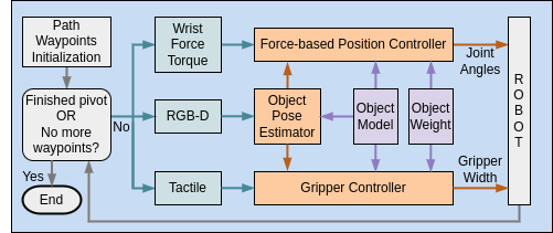
The pivoting task is divided into three sub-tasks. The first task covers visual object pose detection where the 6D pose of the box is estimated. The second task generates the grasp pose, which is placed on a point along the top edge of the box based on a user input. Finally, closed loop gripper width control is used to grasp the object, and further regulates slip during the pivot motion. A force-based end-effector position controller is also used to amend a pre-planned end-effector path, aiming to maintain contact between the grasped box and the surface. The control loop runs until the robot is able to complete the pivoting task, or when all waypoints of the pre-planned path have been executed. This overall structure of the system is illustrated in Fig.3.
III-A Object Pose Estimation
An RGB-D side camera is used to detect the ArUco marker placed in the center of the largest surface of the box. Based on this marker detection as well as the box dimensions, the box pose can be inferred by offsetting the marker’s pose by half of the box’s respective dimension. The 6D pose of the box’s axis of origin is defined at its centre point with an orientation that aligns the axes so that they are parallel with the length, width and height of the box.
III-B Grasp Pose Synthesis
From the box’s pose, a feasible grasp pose is generated using the known dimensions of the box. The gripper grasps the box such that the gripper is perpendicular to the table surface, i.e. the gripper is pointing down into the table. The grasp pose is also positioned ensuring that the sensing elements of the tactile sensors make full contact with the box. Given that there is only one graspable dimension, the robot can only grasp along one surface of the box.
The placement of the grasp pose on the top corner of the box prevents the box from being stopped by the gripper palm during the pivoting motion, and allows it to fit through the gap between the fingers. The grasp point relative to the box, as well as the orientation of the gripper, is maintained during the pivoting action. For a given grasp point, the pivot direction is always chosen such that the grasp point and pivot point are on opposite sides of the box. This is demonstrated in Fig.1.
III-C Closed Loop Control
To successfully pivot the box we employ a robot end-effector position controller and a gripper controller. These controllers will adjust both the robot end-effector path and the gripper width respectively throughout the pivoting motion.
We analyse the expected forces applied to the sensors during the pivot process assuming equilibrium conditions during the pivot action, corresponding to a constant speed rotation, as illustrated in Fig.4. Torque applied on the box by the gravitational force , with the centre of mass assumed to be at the centre of the box, is balanced by the forces applied to it from the pivoting motion .
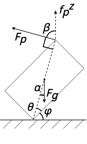
The wrist sensor measured force in the vertical (z) direction is the vertical component of the pivoting force , :
| (1) |
The above equation can then be expressed with respect to the pivot angle between the base of the box and the surface, , and specific properties of the box, including the angle between its base and diagonal, , its mass , and gravity constant :
| (2) |
This expected force profile is used in relation to the force measured by the wrist sensor to control the robot.
Initial Gripper Width: Determining an adequately loose grip is essential to allow the box to rotate in-hand. To grasp the box, the gripper fingers are set to continue closing until the total force in the direction normal to the box surface, as measured by the two tactile sensors, exceeds a threshold.
This force threshold is set to ensure that the gripper does not experience translational slip initially. This requires the static friction force between the gripper fingers and the box to be greater than the pivoting force applied to the box at the start of the motion, when the pivot angle is infinitesimally small. The static friction force is calculated from empirically tested friction coefficient and the normal force exerted through contact as measured by the tactile sensors, giving the grip force threshold:
| (3) |
Force-based Position Controller: The robot force-based position controller controls and updates the arm’s path throughout the pivoting motion.
We represent a complete pivoting motion with the pivot point of the object remaining in contact with the surface by the ideal pivoting force profile described by Equation 2. The controller will then maintain contact by tracking this profile. The force exerted by the robot is controlled by applying a vertical offset to a pre-planned arc path for the end-effector.
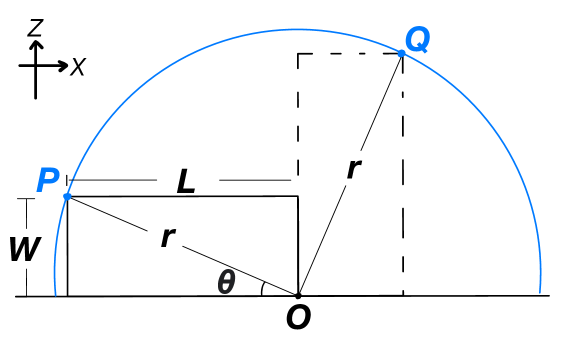
Initially, a Cartesian path consisting of 50 waypoints is generated to traverse an arc parameterised by the box’s dimensions. 50 waypoints are used as a balance between time taken to complete the movement and maintaining the arc with radius as the distance between the grasp point and the pivot point. For a box grasped at the top corner, the radius would become its diagonal, as seen in Fig.5.
To pivot the box from point to point , the movement required to get to each waypoint on the arc trajectory from the starting point is given as:
| (4) |
| (5) |
where is the length of the box, the arc radius is the diagonal of the box and is the pivot angle between the surface and the base of the box.
The MoveIt motion planning API is then used to generate and execute the timed trajectory for the robot end effector between each waypoint. It computes straight line path segments between the start and end using linear interpolation. The velocity and acceleration of the trajectory is then derived with an algorithm termed iterative parabolic time parameterisation, which generates parabolic blends to smooth the planned paths and adhere to velocity and acceleration limits [26].
Using the above information including Equation 2, the position controller is implemented, and described in Alg.1. At each waypoint, the ideal force is predicted using the rotation angle of the box, estimated using vision. The measured force is then compared to the ideal force to produce an error, and accumulated in . The vertical offset that should be applied is then calculated from the force error using Proportional-Integral (PI) control, with proportional constant and integral constant , both empirically tuned. The offset is applied to all waypoints, and adjusted incrementally during each iteration. This aims to maintain the offset that minimises the error between the two force values. The pre-planned waypoint is updated by applying this offset to the vertical dimension, and trajectories are generated by MoveIt so that the robot moves in accordance to the adjustment. If at any point the rotation angle is estimated to be greater than or equal to 90°, it is assumed that the pivot is complete and the program will terminate.
Due to the MoveIt planning computation, the robot pauses momentarily before each consecutive movement to the next waypoint. This causes a discontinuous, slow motion that becomes slower with more waypoints.
Gripper Controller: The slip of the object is controlled to perform the pivoting movement. We estimate the slip type as either translational or rotational. During pivoting, the desired slip is rotational slip and translational slip as a result of gravity should be avoided. We ignore the no slip case as this was not possible for our chosen configuration. Hence it is sufficient to only explicitly detect and control translational slip.
To detect the type of slip, we utilise the direction of force measurements at different points of the tactile sensing elements. Our method uses distributed sensing elements on the tactile sensor, and assumes the tactile sensor consists of nine physical elements in a 3x3 square array [27]. Each element measures the displacement of the tip of the sensing pillar, and predicts applied force from this displacement. We focus on the displacement and force values in the vertical dimension, parallel to gravity, as this is the major indicator of slip.
In the event of gravity-induced translational slip, the downwards movement of the box will be captured by the tactile sensor as a global downwards force across all sensing elements on the tactile sensor. This is in contrast to when the box undergoes rotational slip, where local sensing elements measure forces in different directions, as the centre of rotation is roughly at the centre of the sensor. The direction of the applied force in the vertical dimension is simply taken as the sign of the measured value. We also set a small magnitude threshold of 0.1 to exclude noise. Slip type is only estimated for sensing elements that are detected to be in contact, through an in-built algorithm of the tactile sensors which is based on the normal force applied to the element.
If the tactile sensors detect translational slip, the gripper width incrementally closes until it is no longer detected. Each step of the increment is times the max distance between the gripper fingers. If the tactile sensors detect rotational slip, then the gripper width is unaltered. The gripper will also loosen its grip if at least one of the pillars experience excessive deformation, to prevent damage to the sensors and the box. We choose the displacement threshold to be slightly higher than values seen in trial runs keeping the heaviest box in midair while avoiding slip, representing the expected highest force situation. The gripper control algorithm is summarised in Alg. 2. It is executed at the tactile sensor sample rate of 500 Hz.
IV Experiments
IV-A Setup
The proposed pivoting system was tested using a UR5 robot arm with the Robotiq 2F-85 gripper and a FT-300 Force/Torque sensor attached to the end effector. The fingers of the gripper have two Contactile PapillArray 3x3 tactile sensor arrays attached, capable of measuring 3D displacement, force, and torque [27]. In some experiments involving high-force grasping, the tactile sensors are replaced with flat rubberised fingers to avoid damaging the sensors. The gripper has the tactile sensors mounted unless specified otherwise. The camera used is the Intel RealSense D435i, placed to the side of the robot. The hardware setup is shown in Fig. 6.
Cardboard boxes with varying dimensions are used for the experiment, shown in Fig. 7. Their mass and mass distributions are adjustable by adding iron weights inside.
IV-B Procedure
A series of experiments are designed to verify the validity of our approach. The goal of all experiments is to complete a rotation of the box without lifting it off the surface or letting the box slip out of the gripper’s grasp. A simple pick-and-place method is performed as a baseline. We compare five different methods, including the application of controllers introduced in Section III-C, under four different conditions. Each applicable combination was repeated 10 times for each of the three boxes.
IV-C Methods
Pick&Place: Picking up a box from the centre of its top edge, the robot first lifts up the box completely and then rotates it in the air by , and completes pivoting after lowering it down. The gripper is set to close as hard as possible, with the tactile sensors replaced with flat, rubberised fingers. The lifted height before pivoting is set just high enough so that the robot can complete pivoting without hitting the surface, to represent the lowest effort situation using this method.
Open Loop: No controllers are used. The gripper is set to close as hard as possible and the tactile sensors are also replaced with flat, rubberised fingers. The arm’s trajectory is planned as an ideal arc based on the box’s dimensions.
Vision: A vision-based controller is used. The gripper is set to close as hard as possible with the tactile sensors replaced with flat, rubberised fingers. The arm’s trajectory is planned as an ideal arc based on the box’s dimensions and adjusted with offsets. However, the vertical offset is calculated from the estimated height of the box from the surface.
Gripper: Only the gripper controller is used, both to grasp the object and to control slip during pivoting. The arm’s trajectory is planned as an ideal arc, not updated during the movement.
Force: Only the force-based position controller is used. The gripper is set to close as hard as possible with the tactile sensors replaced with flat, rubberised fingers. The arm’s path is planned as an ideal arc and updated during the movement using the error between measured force and predicted force.
Force+Gripper+Vision: All three sensors are used. The gripper controller is used to grasp the object and control slip. Vision is used to track the rotation angle between the surface and the box’s lowest edge for force estimation. The arm’s path is planned as an ideal arc and updated during the movement by the force-based position controller, and the gripper width is updated by gripper controller.
IV-D Independent Variables
-
1.
Pivoting types: The robot performs two types of pivoting. It either pivots a box from standing on its longer edge to standing on its shorter edge, or from its shorter edge to its longer edge.
-
2.
Noise: A 5cm noise value for the base dimension of the box can be added, causing the arc trajectory to have a larger radius. No noise represents the ideal arc trajectory.
IV-E Evaluation Metrics
To assess the performance of the robot in each experiment, five quantitative measures are established:
-
•
Success Rate (%): The percentage of all attempts where the robot fully completes the rotation.
-
•
Slip Off Rate (%): The percentage of all attempts where the box slips off from the gripper during the movement.
-
•
Lift Up Rate (%): The percentage of all attempts where the box is lifted off the surface during the movement, regardless of whether contact was re-established later during the motion.
-
•
Time Taken (s): The total time it takes the robot to move the object from the start to end position.
-
•
Work (Joules): The amount of both translational work and rotational work done applied by the robot on the object to move the object from the start to goal pose.
Slip off and lift up events are observed by the experimenter, while the work is calculated from force measurements from the wrist mounted force/torque sensor, and displacement derived from the object pose estimation.
A pivot action is considered failed when the robot cannot complete the rotation. Lift up and slip off rates are used to distinguish between perfect success (i.e. neither leaving nor being pushed too hard into the surface) and conditional success, which is less efficient in terms of effort and has a higher risk of damaging the object or environment.
IV-F Results
The detailed results for all experiments can be found in Table I, with the aggregate results presented in Table II. The combined controller approach achieves 100% rate with 0 lift up and 0 slip off events. This approach also requires the least work among all approaches while the pick&place method required the highest work. However, it lags behind other methods in terms of completion time. Instead, the open loop approach requires the least time to complete the movement.
| Short-to-Long Pivot | Long-to-Short Pivot | |||||||||||||||||||
| Without Noise | Added Noise | Without Noise | Added Noise | |||||||||||||||||
| sec | J | sec | J | sec | J | sec | J | |||||||||||||
| Succ. | Lift | Slip | Time | Work | Succ. | Lift | Slip | Time | Work | Succ. | Lift | Slip | Time | Work | Succ. | Lift | Slip | Time | Work | |
| Small Box (Dimensions: cm, Weight: kg) | ||||||||||||||||||||
| Pick&Place | 100 | 100 | 0 | 16.4 | 8.0 | NA | NA | NA | NA | NA | 100 | 100 | 0 | 18.2 | 8.0 | NA | NA | NA | NA | NA |
| Open Loop | 0 | 100 | 0 | - | - | 0 | 100 | 0 | - | - | 100 | 0 | 0 | 10.4 | 2.7 | 0 | 100 | 0 | - | - |
| Vision | 100 | 100 | 0 | 22.7 | 4.4 | 100 | 100 | 0 | 23.2 | 4.7 | 100 | 100 | 0 | 24.1 | 2.2 | 100 | 100 | 0 | 24.3 | 2.3 |
| Gripper | 100 | 0 | 0 | 27.0 | 1.6 | 0 | 100 | 0 | - | - | 100 | 0 | 0 | 29.6 | 1.9 | 0 | 90 | 10 | - | - |
| Force | 100 | 100 | 0 | 22.9 | 6.4 | 100 | 100 | 0 | 23.5 | 5.8 | 100 | 0 | 0 | 23.8 | 3.1 | 100 | 80 | 0 | 21.7 | 2.1 |
| Gripper+Force+Vision | 100 | 0 | 0 | 25.3 | 1.1 | 100 | 0 | 0 | 24.4 | 1.7 | 100 | 0 | 0 | 26.4 | 1.5 | 100 | 0 | 0 | 24.9 | 1.8 |
| Large Box (Dimensions: cm, Weight: kg) | ||||||||||||||||||||
| Pick&Place | 100 | 100 | 0 | 16.1 | 6.6 | NA | NA | NA | NA | NA | 100 | 100 | 0 | 16.6 | 5.9 | NA | NA | NA | NA | NA |
| Open Loop | 0 | 100 | 0 | - | - | 0 | 100 | 0 | - | - | 70 | 0 | 0 | 10.8 | 4.0 | 0 | 100 | 0 | - | - |
| Vision | 0 | 100 | 0 | - | - | 0 | 100 | 0 | - | - | 100 | 90 | 0 | 24.4 | 5.5 | 100 | 100 | 0 | 28.1 | 3.1 |
| Gripper | 100 | 90 | 0 | 26.8 | 2.4 | 30 | 100 | 10 | 28.3 | 4.3 | 100 | 0 | 0 | 26.7 | 1.9 | 100 | 100 | 0 | 34.0 | 2.5 |
| Force | 0 | 100 | 0 | - | - | 0 | 100 | 0 | - | - | 100 | 0 | 0 | 24.4 | 5.4 | 100 | 80 | 0 | 25.1 | 3.3 |
| Gripper+Force+Vision | 100 | 0 | 0 | 25.5 | 1.8 | 100 | 0 | 0 | 25.8 | 1.9 | 100 | 0 | 0 | 26.2 | 2.3 | 100 | 0 | 0 | 26.9 | 1.9 |
| Long Box (Dimensions: cm, Weight: kg) | ||||||||||||||||||||
| Pick&Place | 0 | 100 | 0 | - | - | NA | NA | NA | NA | NA | 0 | 100 | 0 | - | - | NA | NA | NA | NA | NA |
| Open Loop | 90 | 10 | 0 | 9.3 | 8.7 | 0 | 100 | 0 | - | - | 100 | 0 | 0 | 10.8 | 12.7 | 0 | 100 | 0 | - | - |
| Vision | 100 | 100 | 0 | 24.6 | 4.1 | 100 | 100 | 0 | 28.2 | 4.0 | 100 | 100 | 0 | 28.7 | 5.3 | 100 | 100 | 0 | 31.0 | 5.2 |
| Gripper | 90 | 0 | 10 | 28.7 | 3.6 | 90 | 100 | 10 | 35.1 | 9.8 | 100 | 0 | 0 | 29.8 | 7.0 | 0 | 100 | 50 | - | - |
| Force | 100 | 0 | 0 | 23.9 | 4.5 | 100 | 100 | 0 | 24.9 | 4.9 | 100 | 0 | 0 | 26.1 | 7.1 | 100 | 0 | 0 | 27.4 | 4.8 |
| Gripper+Force+Vision | 100 | 0 | 0 | 29.3 | 2.9 | 100 | 0 | 0 | 30.4 | 3.3 | 100 | 0 | 0 | 30.6 | 3.9 | 100 | 0 | 0 | 33.1 | 3.7 |
| sec | J | ||||
|---|---|---|---|---|---|
| Succ. | Lift | Slip | Time | Work | |
| PickPlace | 66.7 | 100 | 0 | 16.8 | 7.1 |
| Open Loop | 30 | 67.5 | 0 | 10.3 | 7.0 |
| Vision | 83.3 | 99.2 | 0 | 25.9 | 4.1 |
| Gripper | 67.5 | 56.7 | 7.5 | 29.6 | 3.9 |
| Force | 83.3 | 55 | 0 | 24.4 | 4.7 |
| Force + Gripper + Vision | 100 | 0 | 0 | 27.4 | 2.3 |
V Discussion
V-A Highest Performance and Robustness
Performance: The combined approach of vision, force-based position and gripper control had the highest success rate and lowest work among all approaches. It was able to adjust both the gripper width and the movement path so that the object was not lifted off the ground. However, the long completion time of 27.4 seconds on average is the disadvantage of our approach. This is due to the motion planning of each subsequent end-effector waypoint when applying the control offset, which requires more time than other approaches. The fastest approach was the open loop method with an average completion time of 10.3 seconds, as it only plans once for the entire trajectory. On the other hand, this also indicates that the pivoting action is capable of faster completion than the traditional pick-and-place method (16.8 seconds on average). If a more responsive control methodology such as pure joint velocity control without planning was implemented, the closed loop solution may also achieve speeds approaching the open loop method.
The lift and slip rates indicate the importance of the gripper controller. For methods that do not use gripper controller, closing the gripper as hard as possible avoids translational slip. This is reflected in the very low slip rate across all methods, even when the boxes have been lifted off the surface. Meanwhile, without the gripper controller, rotational slip could not be achieved consistently, and was prone to influences by other factors such as the box’s mass, shape and mass distribution. Without rotating in the gripper, the pivot point would lose contact with the surface as the box cannot maintain a pose that keeps its diagonal in line with the radius of the trajectory. This corresponds to higher lift rates compared to methods with gripper controller.
Robustness: To test robustness, noise was intentionally added into the system in the form of a 5cm offset to one of the box dimensions. This had the effect of increasing the radius of the initial planned arc trajectory. As expected, the open loop approach always failed in this case. The single-modal closed loop approaches were still capable of completing full pivots in many cases, with success rates of 67.5-83.3%, despite high lift rates of 55-99.2%, corresponding to a frequent deviation from the ideal planned trajectory, but a recovery to complete the pivot. Out of all methods, the combined approach was the most robust, succeeding in all tests.
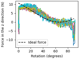
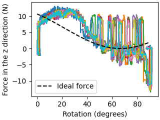
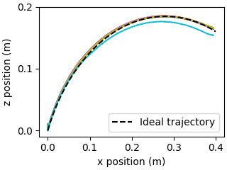
To examine the performance and robustness of our position controller in further detail, we plot the wrist force in the z-direction, as well as the pivot path in Fig. 8. In Fig. 8(a), the measured force profile followed the targeted ideal profile closely. The large negative peaks at the beginning and end of the pivot are due to the initial grasp of the box, and slight overshooting which pushed the box into the surface, respectively. It can be seen in Fig. 8(c) that the pivot could easily adhere to the ideal trajectory in all but one trial.
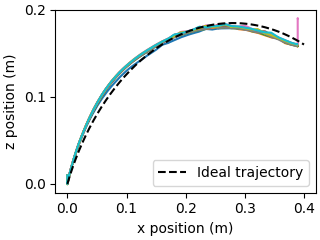
However, when noise is added to the initial planned path, the system can no longer track the force profile as cleanly. In Fig. 8(b), the measured force profile diverted from the calculated ideal, and large fluctuations are also present. This is due to the frequent vertical adjustments that the gripper needs to make in its path to compensate for the applied noise. As compared to the noise-free case when the gripper moved in a relatively smooth motion, the assumption of constant speed is less valid. Between the peaks, during the stop in motion of the robot arm, the force profiles remain close to ideal predictions. Despite diversions from the ideal force profile, the pivot path as shown in Fig. 8(d) remained very close to the ideal plan. Influenced by the increased base dimension of the box, an increase to the radius of the path is observed as pivoting begins, corresponding to the large difference in the force plot. The controller then begins acting and the movement converges back to the ideal path, allowing all trials to pivot successfully. If larger forces are involved when handling heavier or larger objects, however, it may be necessary to also consider the dynamic effects of the robot movement, or otherwise implement smoother movement for the gripper.
V-B Effects of different objects
Mass: During our experiments, it was observed that the mass of the box could directly affect the success rate. For the force-based position and vision control methods performing short-to-long pivots, pivoting the large box was always unsuccessful. The failed cases were caused by the low weight of the large box, which is the lightest out of all three boxes. This could not generate enough torque around the gripper fingers to induce rotational slip for the purpose of pivoting. Sufficient torque about the gripper fingers is necessary to create rotational slip as the the box is more capable of overcoming the friction force generated by the grasp. On the contrary, the long box showed a 0% success rate in terms of the pick&place method. During those experiments, the mass was the main reason for failure as the weight of the box caused too much slip for the robot to rotate the box 90.
Object shape and Mass distribution: Besides the mass, the shape of the objects and their mass distributions also affect the gravitational torque around the gripper fingers. The long-to-short pivoting case has a higher torque than the short-to-long case, since the grasp point is further from the centre of mass, roughly at the centre of the box. This helps to induce rotational slip at the grasp point and complete the pivot action. As seen in Table I, the success rates for the long-to-short pivots were generally higher for all methods, and the lift rates were generally lower. This was especially significant for the single-modal approaches without gripper control, as they lack the means to regulate the extrinsic influence of gravitational torque by varying gripper width.
However, the iron weights used to manually adjust the weight of the boxes would not have been perfectly distributed around the centre, making the estimation of the torque around the fingers less accurate.
V-C Artificial Markers for Pose Estimation
In the vision component of our system, the ArUco marker plays an important role in detecting the object’s pose and further tracking the angle between the surface and the box’s lowest edge among all approaches. More generalisable methods for pose estimation may include point cloud clustering and feature matching in the 3D space [28]. Such algorithms can also be used to derive the dimensions of the object. Although this may introduce inaccuracies to the vision component, our tests have shown that by using closed loop approaches, the system can succeed in the face of such inaccuracies.
V-D Single vs Multi-modal
In our combined approach, all three modules are necessary for the "perfect" pivoting. Based on the results in Table II, each single-modal controller was not able to pivot the box with 100% success rate. Both vision and force-based position controllers have higher success rate than the gripper module, as our chosen challenge scenario introduced noise to the ideal arc trajectory, which could only be amended by those two controllers. For some specific scenarios (i.e. light weight box), the box can easily be lifted without inducing enough rotational slip, and the gripper controller can be more important to complete pivoting. In the case of vision control, the robot only begins to offset the trajectory after the box has been lifted, causing a high lift rate of 99.2%.
VI Conclusions and Future Work
We present a closed loop, multi-modal solution utilising vision, force/torque and tactile sensors for manipulating objects via pivoting. The system is able to control the robot to maintain contact with the surface, and modulate the gripper width to induce the desired type of slip.
Based on the experiments conducted, we observe a clear advantage of our approach in terms of success rate, robustness, as well as the work done in pivoting the box compared to the open loop and pick-and-place method. The limitations of our approach are its slow execution speed. For future works, we will consider implementing joint velocity control, as well as removing the use of markers for object detection and generalising this approach for many different shapes of objects. Additionally, using learning to perform force-based position and gripper width control will be considered.
This paper should be considered as a proof-of-concept that demonstrates the feasibility of our pivoting approach by taking advantage of multi-modal sensing. While our work featured only cubic objects tracked via fiducial markers, we believe that our approach can be generalised to rigid objects with modifications. The marker-based pose detection can be swapped with a model-based 6D pose detector [29]. A model-based [30] or model-free grasp synthesis approach [31] can be used for obtaining a robust 6D grasp pose. In our work, pivoting on an edge of the box was obvious, however, to generalise it to any given object, further geometric reasoning would be needed for finding a suitable pivot point or edge on the object. Furthermore, a more sophisticated control approach might be needed for contact configuration regulation [18].
References
- [1] Y. Aiyama, M. Inaba, and H. Inoue, “Pivoting: A new method of graspless manipulation of object by robot fingers,” in IROS, 1993.
- [2] S. Saeedvand, H. Mandala, and J. Baltes, “Hierarchical deep reinforcement learning to drag heavy objects by adult-sized humanoid robot,” Applied Soft Computing, 2021.
- [3] N. C. Dafle, A. Rodriguez, R. Paolini, B. Tang, S. S. Srinivasa, M. Erdmann, M. T. Mason, I. Lundberg, H. Staab, and T. Fuhlbrigge, “Extrinsic dexterity: In-hand manipulation with external forces,” in ICRA, 2014.
- [4] M. Costanzo, G. De Maria, and C. Natale, “Slipping control algorithms for object manipulation with sensorized parallel grippers,” in ICRA, 2018.
- [5] T. M. Huh, H. Choi, S. Willcox, S. Moon, and M. R. Cutkosky, “Dynamically reconfigurable tactile sensor for robotic manipulation,” IEEE Robotics and Automation Letters, 2020.
- [6] M. Meier, F. Patzelt, R. Haschke, and H. J. Ritter, “Tactile convolutional networks for online slip and rotation detection,” in International Conference on Artificial Neural Networks, pp. 12–19, Springer, 2016.
- [7] J. Toskov, R. Newbury, M. Mukadam, D. Kulić, and A. Cosgun, “In-hand gravitational pivoting using tactile sensing,” in Conference on Robot Learning, 2022.
- [8] M. Raessa, W. Wan, and K. Harada, “Planning to repose long and heavy objects considering a combination of regrasp and constrained drooping,” Assembly Automation, vol. 41, no. 3, pp. 324–332, 2021.
- [9] A. Zhang, K. Koyama, W. Wan, and K. Harada, “Manipulation planning for large objects through pivoting, tumbling, and regrasping,” Applied Sciences, vol. 11, no. 19, p. 9103, 2021.
- [10] F. Shi, M. Zhao, M. Murooka, K. Okada, and M. Inaba, “Aerial regrasping: Pivoting with transformable multilink aerial robot,” in ICRA, 2020.
- [11] E. Yoshida, M. Poirier, J.-P. Laumond, O. Kanoun, F. Lamiraux, R. Alami, and K. Yokoi, “Pivoting based manipulation by a humanoid robot,” Autonomous Robots, vol. 28, no. 1, pp. 77–88, 2010.
- [12] R. Antonova, S. Cruciani, C. Smith, and D. Kragic, “Reinforcement learning for pivoting task,” arXiv preprint arXiv:1703.00472, 2017.
- [13] Y. Hou, Z. Jia, and M. T. Mason, “Fast planning for 3d any-pose-reorienting using pivoting,” in ICRA, pp. 1631–1638, IEEE, 2018.
- [14] Y. Hou, Z. Jia, and M. T. Mason, “Reorienting objects in 3d space using pivoting,” arXiv preprint arXiv:1912.02752, 2019.
- [15] B. Siciliano and L. Villani, Robot force control. Springer, 1999.
- [16] D. Ma, S. Dong, and A. Rodriguez, “Extrinsic contact sensing with relative-motion tracking from distributed tactile measurements,” in ICRA, 2021.
- [17] A. Molchanov, O. Kroemer, Z. Su, and G. S. Sukhatme, “Contact localization on grasped objects using tactile sensing,” in IROS, 2016.
- [18] N. Doshi, O. Taylor, and A. Rodriguez, “Manipulation of unknown objects via contact configuration regulation,” in ICRA, 2022.
- [19] F. R. Hogan, J. Ballester, S. Dong, and A. Rodriguez, “Tactile dexterity: Manipulation primitives with tactile feedback,” in ICRA, 2020.
- [20] K.-T. Yu and A. Rodriguez, “Realtime state estimation with tactile and visual sensing for inserting a suction-held object,” in IROS, 2018.
- [21] Q. Li, O. Kroemer, Z. Su, F. F. Veiga, M. Kaboli, and H. J. Ritter, “A review of tactile information: Perception and action through touch,” IEEE Transactions on Robotics, vol. 36, no. 6, pp. 1619–1634, 2020.
- [22] M. Costanzo, G. De Maria, and C. Natale, “Two-fingered in-hand object handling based on force/tactile feedback,” IEEE Transactions on Robotics, vol. 36, no. 1, pp. 157–173, 2019.
- [23] M. Costanzo, G. De Maria, and C. Natale, “Detecting and controlling slip through estimation and control of the sliding velocity,” Applied Sciences, vol. 13, no. 2, p. 921, 2023.
- [24] C. Wang, X. Zang, H. Zhang, H. Chen, Z. Lin, and J. Zhao, “Status identification and object in-hand reorientation using force/torque sensors,” IEEE Sensors Journal, vol. 21, no. 18, pp. 20694–20703, 2021.
- [25] Y. Chen, C. Prepscius, D. Lee, and D. D. Lee, “Tactile velocity estimation for controlled in-grasp sliding,” IEEE Robotics and Automation Letters, vol. 6, no. 2, pp. 1614–1621, 2021.
- [26] T. Kunz and M. Stilman, “Turning paths into trajectories using parabolic blends,” tech. rep., Georgia Institute of Technology, 2011.
- [27] H. Khamis, R. I. Albero, M. Salerno, A. S. Idil, A. Loizou, and S. J. Redmond, “Papillarray: An incipient slip sensor for dexterous robotic or prosthetic manipulation–design and prototype validation,” Sensors and Actuators A: Physical, vol. 270, pp. 195–204, 2018.
- [28] J. Guo, X. Xing, W. Quan, D.-M. Yan, Q. Gu, Y. Liu, and X. Zhang, “Efficient center voting for object detection and 6d pose estimation in 3d point cloud,” IEEE Transactions on Image Processing, 2021.
- [29] Y. Xiang, T. Schmidt, V. Narayanan, and D. Fox, “Posecnn: A convolutional neural network for 6d object pose estimation in cluttered scenes,” 2018.
- [30] J. Tremblay, T. To, B. Sundaralingam, Y. Xiang, D. Fox, and S. Birchfield, “Deep object pose estimation for semantic robotic grasping of household objects,” in Conference on Robot Learning (CoRL), 2018.
- [31] A. Mousavian, C. Eppner, and D. Fox, “6-dof graspnet: Variational grasp generation for object manipulation,” in IEEE/CVF International Conference on Computer Vision (CVPR), 2019.