Particle-hole symmetry protects spin-valley blockade in graphene quantum dots
Abstract
Particle-hole symmetry plays an important role for the characterization of topological phases in solid-state systems Zirnbauer (2021). It is found, for example, in free-fermion systems at half filling, and it is closely related to the notion of antiparticles in relativistic field theories Maurice (1930). In the low energy limit, graphene is a prime example of a gapless particle-hole symmetric system described by an effective Dirac equation McCann and Koshino (2013); Castro Neto et al. (2009), where topological phases can be understood by studying ways to open a gap by preserving (or breaking) symmetries Haldane (1988); Qi and Zhang (2011). An important example is the intrinsic Kane-Mele spin-orbit gap of graphene, which leads to a lifting of the spin-valley degeneracy and renders graphene a topological insulator in a quantum spin Hall phase Kane and Mele (2005), while preserving particle-hole symmetry. Here, we show that bilayer graphene allows realizing electron-hole double quantum-dots that exhibit nearly perfect particle-hole symmetry, where transport occurs via the creation and annihilation of single electron-hole pairs with opposite quantum numbers. Moreover, we show that this particle-hole symmetry results in a protected single-particle spin-valley blockade. The latter will allow robust spin-to-charge conversion and valley-to-charge conversion, which is essential for the operation of spin and valley qubits.
Carbon-based materials, such as monolayer and bilayer graphene, are interesting hosts for spin and spin-valley qubits, thanks to their weak spin-orbit (SO) coupling Kane and Mele (2005); Konschuh et al. (2012); Kurzmann et al. (2021); Banszerus et al. (2021a) and weak hyperfine interaction Wojtaszek et al. (2014); Fischer and Loss (2009). Bilayer graphene (BLG) is attracting in particular increasing attention, as it presents a gate-tunable band gap, McCann and Koshino (2013); Icking et al. (2022), which can be used to electrostatically confine charge carriers into quantum point contacts and quantum dots (QDs) Eich et al. (2018); Banszerus et al. (2020a, 2021a); Kurzmann et al. (2021); Garreis et al. (2021); Lee et al. (2020). The small size of this gap (up to meV) allows forming ambipolar quantum dots, which is not possible in standard semiconductors Banszerus et al. (2018, 2020b); Tong et al. (2021). Another attracting feature is that, at low energy, charge carriers have an orbital magnetic moment caused by the finite Berry curvature McCann and Koshino (2013); Knothe and Fal’ko (2018, 2020). These orbital magnetic moments are aligned perpendicular to the BLG plane and allow to control the valley degree of freedom, as they have opposite signs for the two valleys ( and ) and for electrons and holes, as illustrated in Fig. 1a. This property is a consequence of the particle-hole symmetry that is imprinted in the low-energy Hamiltonian of bilayer graphene,
as well as on the intrinsic Kane-Mele SO coupling term Kane and Mele (2005); Konschuh et al. (2012). Here, is the effective mass of the charge carriers in BLG with the free electron mass , are momentum operators and are Pauli matrices () acting on the spin, valley and sublattice space, respectively. Both and are invariant under the particle-hole transformation , which effectively flips the sublattice, the valley, and the spin indices, . As a consequence, the hole spectrum in BLG mirrors the electron spectrum around the and points.
This symmetry remains true in BLG quantum dots. In this case the orbital states are quantized and form shells with four states, which are grouped by the intrinsic spin-orbit coupling into Kramers’ doublets, , and , . Every electron state in the energetically lower (higher) Kramers’ pair in the conduction band has a corresponding hole state in the energetically higher (lower) Kramers’ pair in the valence band, as illustrated in Fig. 1b. This is in stark contrast to the single-particle spectrum of QDs in carbon nanotubes, where the spin-orbit coupling caused by the curvature breaks the particle-hole symmetry Pei et al. (2012); Laird et al. (2015). Here, we show that this symmetry is almost perfectly preserved also when electron and holes are physically separated into different quantum dots and that it leads to a very strong single-particle blockade in the transport through electron-hole double quantum dots (DQDs).
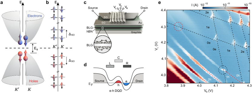
The DQD devices are fabricated as schematically shown in Fig. 1c. The devices consist of BLG encapsulated between two crystals of hexagonal boron nitride (hBN) resting on a graphite crystal that acts as a back gate. A pair of metallic split gates (SGs) on top is used to create a narrow conducting channel (see Methods). Two layers of interdigitated finger gates across the channel are used to modulate the band-edge profile along the channel and to confine electrons and holes in neighboring QDs, as illustrated in Fig. 1d Banszerus et al. (2021b, a). The charge stability diagram in Fig. 1e gives an overview of the different charge configurations of the investigated device at mV (see Suppl. Sec. A, for reversed bias). At finger gate voltages and 4.1 V, a hole QD is formed underneath the central finger gate C, whereas at and 4.1 V an electron-electron DQD is formed under the left (L) and right (R) gate. The dashed lines indicate the charge transitions of the electron (black) and hole (red) QDs. The intersections of the electron and hole charging lines, correspond to the formation of an ambipolar electron-hole DQD.
We now focus on the triple point of the charge transition , highlighted by the black dashed-circle in Fig. 1e. For positive bias voltages, a steady tunnel current through the DQD involves the transition , i.e. it is only possible if electron-hole pairs with opposite quantum numbers (e.g. and ) can continuously be created. As the SO coupling has opposite sign for electrons and holes, this is possible only in two configurations, and , illustrated in the two panels of Fig. 2a. These two configurations, which are energetically offset by , result in two sharp current-peaks in the bias triangle, as shown in Fig. 2b. The value of extracted from the separation of the peaks along the detuning axis eV, is in excellent agreement with the value of measured in an electron-electron DQD realized in the same device (eV, see Suppl. Sec. B) and in other BLG QD experiments Kurzmann et al. (2021); Banszerus et al. (2020c, 2021a). The separation of the two resonances remains constant when applying a perpendicular magnetic field, only their position changes with respect to the baseline of the bias triangle, as can be seen in Fig. 2c. In contrast, the separation between and increases slightly when applying a parallel magnetic field, and a third resonance, , appears in between, as shown in Fig. 2d. This behavior can be well understood, as explained below.
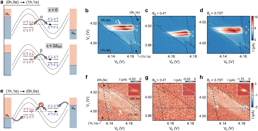
Before turning to this, we consider the case of negative bias voltage applied to the e-h DQD device. In this case, tunnel transport through the DQD requires the continuous annihilation of electron-hole pairs, i.e. , which is only possible if the electron and hole have opposite quantum numbers. However, since electrons and holes tunnel in from the leads with random quantum numbers, transport is blocked as soon as the QDs are occupied by charge carriers with incompatible quantum numbers, as sketched in Fig. 2e. This blockade is robust up to very high detuning energies, because it can only be overcome by involving excited states that are separated in energy from the low energy spectrum by the band-gap, which is typically of the order of meV. The blockade is nicely visible in Fig. 2f, where the tunnel current inside the bias triangle is entirely suppressed, except for a faint contribution that can be attributed to co-tunneling. The current is slightly enhanced only at the corners of the bias triangle (see dashed circles), which correspond to the configurations where the electron or hole states are aligned with the Fermi level of source or drain, respectively. Under this condition, incompatible charge-carriers can tunnel back into the leads and new ones, possibly with matching quantum numbers, can enter the QD, lifting the blockade and allowing a small current through the DQD. This is confirmed by measurements on another DQD (Suppl. Sec. C) and by simulations based on the single particle spectrum of BLG QDs and Pauli’s master equation Bonet et al. (2002); Knothe et al. (2022) (Suppl. Sec. D), which shows the lifting of the blockade only at the corners of the bias triangle, as shown in the inset of Fig. 2f-h. Applying perpendicular magnetic fields leaves the blockade intact and reduces the co-tunneling current below the noise floor Banszerus et al. (2021a); Möller et al. (2021), as shown in Fig. 2g. The difference between the average current inside the bias triangle and the co-tunneling current outside is below 10 fA, i.e not measurable. For parallel magnetic fields, the blockade also remains intact, but with a stronger enhancement of the tunnel current at the corners of the triple point, which is in agreement with the simulation (see Fig. 2h).
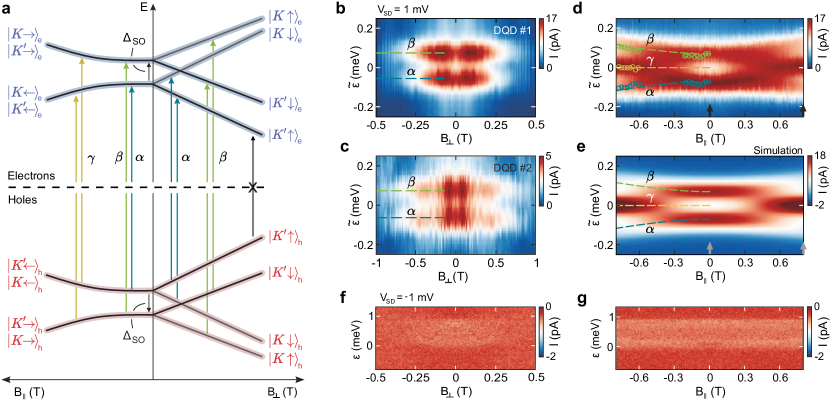
The picture of the symmetry-protected valley blockade presented above is based on the careful analysis of all possible transitions between single-hole and single-electron states in the left and right QD, and on magneto-transport measurements that support the assignment of the states involved into the various transport processes. The magnetic-field dependent energy dispersion of the first hole and electron states is depicted in Fig. 3a. When applying a perpendicular magnetic field, , the degeneracy of the Kramers’ pairs is lifted, and each state shifts due to the spin and valley Zeeman effect . Here, is the Bohr magneton, the spin g-factor Mani et al. (2012); Sichau et al. (2019); Lyon et al. (2017) and the valley g-factor, which quantifies the strength of the Berry curvature induced valley-dependent orbital magnetic moment Knothe and Fal’ko (2020). From Fig. 2c and Suppl. Fig. S5b, we extract for our DQD system. Electrons and holes with opposite quantum numbers experience the same ”Zeeman shift”, and therefore, the splitting between the and transitions remains constant with . This is clearly reflected in the magneto-transport measurements presented in Fig. 3b,c, which show the current measured along the detuning axis of the triple point (see arrow in Fig. 2b) as a function of .
The situation is different for in-plane magnetic fields, , where the spin-Zeeman effect competes with the SO coupling, which polarizes the spins out-of-plane for zero -field Konschuh et al. (2012). With increasing , the spins are tilted into the plane of the BLG, aiming for the same spin direction within a Kramers’ pair, and for opposite spin directions in different Kramers’ pairs (see Fig. 3a, left side). The energy difference between Kramers’ pairs increases according to . This means that the required detuning for the transition decreases, while the one for the transition increases, as can be seen in Fig. 3d. Both and eventually vanish for T, as the overlap between states in different Kramers’ pairs is reduced with the increasing tilt of the spins into the plane of the BLG. Instead, transitions involving states from the same Kramers’ pair of electron and hole states become possible, i.e. pair-creation of the form or . They appear as a third resonance, , which is nicely visible in Fig. 3d. This behavior is confirmed by our simulation, assuming the energy spectrum in Fig. 3a with eV, and .
We confirm the robustness of the blockade for both perpendicular (Fig. 3f) and parallel (Fig. 3g) magnetic fields by repeating the measurements of Figs. 3b,d for negative bias. As argued above, the robustness is a direct consequence of the absence of energetically accessible excited states and of the particle-hole symmetry manifested in the spin and valley texture of our system, which forbids ground-state to ground-state transitions. This is in stark contrast to the usual singlet-triplet Pauli-blockade in conventional semiconductors Johnson et al. (2005); Borselli et al. (2011), which can be lifted by tunneling via excited states. The robustness of the blockade also indicates that (i) spin- or valley-flipping tunnel processes are negligible, and (ii) there is no mixing between the states within a Kramers’ pair.
The experimental data are fully consistent with a description of the electron-hole DQD that is particle-hole symmetric. It should be noticed, however, that such a symmetry is not a priori granted in the system, since electrons and holes are physically separated into two different QDs on different layers of the BLG, and that the inversion symmetry is broken due to the electric displacement field, as illustrated by the schematic in Fig. 4a. Note that that the displacement field induced extrinsic Rashba SO coupling is not relevant for breaking the electron-hole symmetry, as discussed in Suppl. Sec. E. There are, however, other two possible symmetry breaking mechanisms. The first one is a difference in the valley g-factors for electrons and holes, which might be possible since the valley g-factor sensibly depends on the geometry of the QD Knothe and Fal’ko (2020); Tong et al. (2021); Knothe et al. (2022) and electrons and holes sit in two different QDs. Different valley g-factors, i.e. , would break the electron-hole symmetry of the system at finite (see Fig. 4b), and lead to a splitting of the and resonances with increasing (see Suppl. Sec. F). The second mechanism that could break the electron-hole symmetry is a difference in SO coupling for electrons and holes, . This could originate from the fact that at low -values electrons and holes are located on the different layers of BLG McCann and Koshino (2013); Banszerus et al. (2020c). Thus, they can experience a different proximity-enhanced SO coupling, caused by varying inter-atomic distances or crystallographic orientations between BLG and the top and bottom hBN crystal. Assuming different SO coupling energies in the top (t) and bottom (b) layer (see Fig. 4a,b), the Kane-Mele spin-orbit Hamiltonian of BLG takes then the form Banszerus et al. (2020c)
which breaks the layer symmetry. Such a layer dependent SO coupling would cause a splitting of the transition with a separation proportional to the asymmetry of the SO coupling between the two layers .
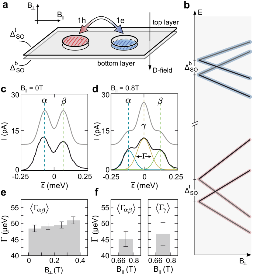
To quantify these effects, we extract the full width at half maximum () of the resonances , , and by fitting Gaussian line shapes and assuming a constant background and an equal width of the and peaks (see Fig. 4c,d). For increasing , we observe a slight broadening of the and resonance, as shown in Fig. 4e. Attributing this broadening entirely to a difference of valley g-factors between the electron and hole QD, we get an upper limit for the valley g-factor mismatch below 1% of , which is consistent with the high symmetry of our gate design. For parallel magnetic fields, Fig. 4f shows that the average width is comparable with , indicating very similar SO couplings in the two layers. From the uncertainty of the line widths, we estimate the layer asymmetry of the Kane-Mele SO coupling to be eV, i.e below 10% of .
This careful analysis confirms that the system is very close to perfect particle-hole symmetric, with a rich and well-understood single-particle spectrum, in full agreement with the topologically non-trivial Kane-Mele model of a quantum spin Hall insulator.
Moreover, we demonstrated that the electron-hole symmetry leads to a strong single-particle spin and valley blockade, which is robust up to high detuning energies.
This is in contrast to singlet-triplet Pauli spin blockade typically observed in conventional semiconductors Johnson et al. (2005); Borselli et al. (2011) (including BLG Tong et al. (2022)), where the blockade is restricted to detuning energies below the singlet-triplet splitting, which can be limited by a finite valley splitting as e.g. in silicon Borselli et al. (2011).
Furthermore, at finite magnetic fields, the electron-hole symmetry protected blockade in BLG cannot be lifted by spin and valley relaxation, as observed in GaAs Johnson et al. (2005).
The symmetry protected spin-valley blockade mechanism in BLG allows for spin-to-charge and valley-to-charge conversion, making it a promising read-out mechanism for spin and valley qubits.
Methods
Sample fabrication.
The devices are fabricated from mechnically exfoliated BLG flakes encapsulated between two hBN crystals of approximately 25 nm thickness using conventional van-der-Waals stacking techniques. A graphite flake is used as a BG. Cr/Au SGs with a lateral separation of 150 nm are deposited on top of the heterostructure. Isolated from the SGs by 15 nm thick atomic layer deposited Al2O3, we fabricate two layers of 70 nm wide FGs with a pitch of 150 nm. Details of the fabrication process can be found in Ref. Banszerus et al. (2020a).
Measurement technique.
All measurements are performed in a dilution refrigerator at a base temperature of mK, using standard DC measurement techniques.
QDs are created following previous studies of gate-defined BLG QDs Eich et al. (2018); Tong et al. (2021); Banszerus et al. (2021b).
Throughout the experiment, a constant BG voltage of V and a SG voltage of V is applied to define a p-type channel between source and drain. The estimated band gap is around 20 meV. For better comparability, the data in Figs. 3b,c,f,g is shown symmetrically around zero magnetic field.
Acknowledgements
The authors thank F. Lentz, S. Trellenkamp and D. Neumeier for help with sample fabrication.
This project has received funding from the European Union’s Horizon 2020 research and innovation programme under grant agreement No. 881603 (Graphene Flagship) and from the European Research Council (ERC) under grant agreement No. 820254, the Deutsche Forschungsgemeinschaft (DFG, German Research Foundation) under Germany’s Excellence Strategy - Cluster of Excellence Matter and Light for Quantum Computing (ML4Q) EXC 2004/1 - 390534769, through DFG (STA 1146/11-1), and by the Helmholtz Nano Facility Albrecht et al. (2017). K.W. and T.T. acknowledge support from JSPS KAKENHI (Grant Numbers 19H05790, 20H00354 and 21H05233).
Data availability
The data supporting the findings are available in a Zenodo repository under accession code XXX.
Author contributions
L.B. C.V. and C.S. conceived this experiment.
L.B., S.M., K.H. and E.I. fabricated the device, L.B., S.M. and C.V. performed the measurements and analyzed the data. S.M. and F.H. performed the simulation of the current. K.W. and T.T. synthesized the hBN crystals. C.V. and C.S. supervised the project. L.B., S.M., C.V., F.H. and C.S. wrote the manuscript with contributions from all authors. L.B. and S.M. contributed equally to this work.
Competing interests
The authors declare no competing interests.
References
- Zirnbauer (2021) M. R. Zirnbauer, J. Math. Phys. 62, 021101 (2021).
- Maurice (1930) D. P. A. Maurice, Proc. R. Soc. London A 126, 360 (1930).
- McCann and Koshino (2013) E. McCann and M. Koshino, Rep. Prog. Phys. 76, 056503 (2013).
- Castro Neto et al. (2009) A. H. Castro Neto, F. Guinea, N. M. R. Peres, K. S. Novoselov, and A. K. Geim, Rev. Mod. Phys. 81, 109 (2009).
- Haldane (1988) F. D. M. Haldane, Phys. Rev. Lett. 61, 2015 (1988).
- Qi and Zhang (2011) X.-L. Qi and S.-C. Zhang, Rev. Mod. Phys. 83, 1057 (2011).
- Kane and Mele (2005) C. L. Kane and E. J. Mele, Phys. Rev. Lett. 95, 226801 (2005).
- Konschuh et al. (2012) S. Konschuh, M. Gmitra, D. Kochan, and J. Fabian, Phys. Rev. B 85, 115423 (2012).
- Kurzmann et al. (2021) A. Kurzmann, Y. Kleeorin, C. Tong, R. Garreis, A. Knothe, M. Eich, C. Mittag, C. Gold, F. K. de Vries, K. Watanabe, T. Taniguchi, V. Fal’ko, Y. Meir, T. Ihn, and K. Ensslin, Nat. Commun. 12, 6004 (2021).
- Banszerus et al. (2021a) L. Banszerus, S. Möller, C. Steiner, E. Icking, S. Trellenkamp, F. Lentz, K. Watanabe, T. Taniguchi, C. Volk, and C. Stampfer, Nat. Commun. 12, 5250 (2021a).
- Wojtaszek et al. (2014) M. Wojtaszek, I. J. Vera-Marun, E. Whiteway, M. Hilke, and B. J. van Wees, Phys. Rev. B 89, 035417 (2014).
- Fischer and Loss (2009) J. Fischer and D. Loss, Science 324, 1277 (2009).
- Icking et al. (2022) E. Icking, L. Banszerus, F. Wörtche, F. Volmer, P. Schmidt, C. Steiner, S. Engels, J. Hesselmann, M. Goldsche, K. Watanabe, T. Taniguchi, C. Volk, B. Beschoten, and C. Stampfer, Adv. Electron. Mater. 8, 2200510 (2022).
- Eich et al. (2018) M. Eich, R. Pisoni, A. Pally, H. Overweg, A. Kurzmann, Y. Lee, P. Rickhaus, K. Watanabe, T. Taniguchi, K. Ensslin, and T. Ihn, Nano Lett. 18, 5042 (2018).
- Banszerus et al. (2020a) L. Banszerus, A. Rothstein, T. Fabian, S. Möller, E. Icking, S. Trellenkamp, F. Lentz, D. Neumaier, K. Watanabe, T. Taniguchi, F. Libisch, C. Volk, and C. Stampfer, Nano Lett. 20, 7709 (2020a).
- Garreis et al. (2021) R. Garreis, A. Knothe, C. Tong, M. Eich, C. Gold, K. Watanabe, T. Taniguchi, V. Fal’ko, T. Ihn, K. Ensslin, and A. Kurzmann, Phys. Rev. Lett. 126, 147703 (2021).
- Lee et al. (2020) Y. Lee, A. Knothe, H. Overweg, M. Eich, C. Gold, A. Kurzmann, V. Klasovika, T. Taniguchi, K. Wantanabe, V. Fal’ko, T. Ihn, K. Ensslin, and P. Rickhaus, Phys. Rev. Lett. 124, 126802 (2020).
- Banszerus et al. (2018) L. Banszerus, B. Frohn, A. Epping, D. Neumaier, K. Watanabe, T. Taniguchi, and C. Stampfer, Nano Lett. 18, 4785 (2018).
- Banszerus et al. (2020b) L. Banszerus, S. Möller, E. Icking, K. Watanabe, T. Taniguchi, C. Volk, and C. Stampfer, Nano Lett. 20, 2005 (2020b).
- Tong et al. (2021) C. Tong, R. Garreis, A. Knothe, M. Eich, A. Sacchi, K. Watanabe, T. Taniguchi, V. Fal’ko, T. Ihn, K. Ensslin, and A. Kurzmann, Nano Lett. 21, 1068 (2021).
- Knothe and Fal’ko (2018) A. Knothe and V. Fal’ko, Phys. Rev. B 98, 155435 (2018).
- Knothe and Fal’ko (2020) A. Knothe and V. Fal’ko, Phys. Rev. B 101, 235423 (2020).
- Pei et al. (2012) F. Pei, E. A. Laird, G. A. Steele, and L. P. Kouwenhoven, Nat. Nanotechnol. 7, 630 (2012).
- Laird et al. (2015) E. A. Laird, F. Kuemmeth, G. A. Steele, K. Grove-Rasmussen, J. Nygård, K. Flensberg, and L. P. Kouwenhoven, Rev. Mod. Phys. 87, 703 (2015).
- Banszerus et al. (2021b) L. Banszerus, A. Rothstein, E. Icking, S. Möller, K. Watanabe, T. Taniguchi, C. Stampfer, and C. Volk, Appl. Phys. Lett. 118, 103101 (2021b).
- Banszerus et al. (2020c) L. Banszerus, B. Frohn, T. Fabian, S. Somanchi, A. Epping, M. Müller, D. Neumaier, K. Watanabe, T. Taniguchi, F. Libisch, B. Beschoten, F. Hassler, and C. Stampfer, Phys. Rev. Lett. 124, 177701 (2020c).
- Bonet et al. (2002) E. Bonet, M. M. Deshmukh, and D. C. Ralph, Phys. Rev. B 65, 045317 (2002).
- Knothe et al. (2022) A. Knothe, L. I. Glazman, and V. I. Fal’ko, New J. Phys. 24, 043003 (2022).
- Möller et al. (2021) S. Möller, L. Banszerus, A. Knothe, C. Steiner, E. Icking, S. Trellenkamp, F. Lentz, K. Watanabe, T. Taniguchi, L. I. Glazman, V. I. Fal’ko, C. Volk, and C. Stampfer, Phys. Rev. Lett. 127, 256802 (2021).
- Mani et al. (2012) R. G. Mani, J. Hankinson, C. Berger, and W. A. de Heer, Nat. Commun. 3, 996 (2012).
- Sichau et al. (2019) J. Sichau, M. Prada, T. Anlauf, T. J. Lyon, B. Bosnjak, L. Tiemann, and R. H. Blick, Phys. Rev. Lett. 122, 046403 (2019).
- Lyon et al. (2017) T. J. Lyon, J. Sichau, A. Dorn, A. Centeno, A. Pesquera, A. Zurutuza, and R. H. Blick, Phys. Rev. Lett. 119, 066802 (2017).
- Johnson et al. (2005) A. C. Johnson, J. R. Petta, C. M. Marcus, M. P. Hanson, and A. C. Gossard, Phys. Rev. B 72, 165308 (2005).
- Borselli et al. (2011) M. G. Borselli, K. Eng, E. T. Croke, B. M. Maune, B. Huang, R. S. Ross, A. A. Kiselev, P. W. Deelman, I. Alvarado-Rodriguez, A. E. Schmitz, M. Sokolich, K. S. Holabird, T. M. Hazard, M. F. Gyure, and A. T. Hunter, Appl. Phys. Lett. 99, 063109 (2011).
- Tong et al. (2022) C. Tong, A. Kurzmann, R. Garreis, W. W. Huang, S. Jele, M. Eich, L. Ginzburg, C. Mittag, K. Watanabe, T. Taniguchi, K. Ensslin, and T. Ihn, Phys. Rev. Lett. 128, 067702 (2022).
- Albrecht et al. (2017) W. Albrecht, J. Moers, and B. Hermanns, Journal of Large-Scale Research Facilities 3, 112 (2017).