A Comparison of Rosenbrock-Wanner and Crank-Nicolson Time Integrators for Atmospheric Modelling
Semi-implicit time discretisations are a popular choice for non-hydrostatic atmospheric models, since they negate the time step limitation associated with the explicit solution of acoustic and gravity waves [21, 20]. This is particularly true for finite element spatial discretisations using Gauss-Lobatto quadrature rules, since unlike spectral element or discontinuous Galerkin methods using inexact spatial integration, these finite element methods have non-diagonal mass matrices which require the implicit solution of linear systems even for the case of explicit time integration schemes. These implicit non-linear systems are commonly solved using Newton’s method, for which the residual vector is discretised using a second order, time centered (or off-centered) Crank-Nicolson scheme, or some similar iterative method. However due to computational performance limitations, the non-linear solver is typically truncated to a fixed number of iterations, rather than to the convergence of the residual below some specified tolerance. Moreover in order to further improve computational performance, the Jacobian operator used to determine the descent direction at each iteration is often approximated by omitting terms that are not strongly related to the fast wave dynamics, the use of vertical reference profiles, and the re-use of the same Jacobian between non-linear iterations or even time steps. Consequently this approximate solution may be regarded as a quasi-Newton method, rather than a full Newton method for which the Jacobian would incorporate all derivatives of the residual vector with respect to all solution variables, and be re-assembled at each non-linear iteration.
As an alternative to such a scheme, here we consider the use of Rosenbrock-Wanner (RoW) methods, where a finite number of non-linear iterations are replaced by a fixed number of implicit Runge-Kutta stages, for which the weights are chosen so as to satisfy specific order and stability conditions [7, 24]. In the current study we limit ourselves to four stage schemes since this is the same number of iterations used as a default in the Crank-Nicolson (CN) quasi-Newton scheme in the UK Met Office’s LFRic dynamical core [21], the model we use to compare these schemes in the present study. The four-stage, third order RoW schemes considered here are for the most part stiffly-stable methods which are well suited to geophysical systems that involve fast acoustic and gravity waves.
The 3D compressible Euler equations used to simulate the dynamics of a dry atmosphere include both prognostic equations for the velocity, the density and the thermodynamic variable, and an algebraic equation, in the form of an equation of state. Block factorisation of the full coupled system, together with a lumped approximation to the velocity space mass matrix, leads to a non-singular Helmholtz equation for the pressure [20]. This resultant Helmholtz equation may be used as an approximate preconditioner for the original coupled system of equations. In order to recover the original coupled system from this Helmholtz equation (ignoring complications with the spatial discretisation due to mass lumping), one would have to differentiate twice in time. Such equations are known as "index-2" partial differential algebraic equations (PDAEs). Consequently the RoW methods studied here must also support index-2 PDAEs in order to allow for the use of the Helmholtz pressure equation as an approximate preconditioner for the full coupled system.
RoW methods (for which only an approximate Jacobian is required) have shown promise for the solution of the incompressible Navier-Stokes equations in two [10] and three [4] spatial dimensions, which also involve an index-2 PDAE elliptic equation, in the form of a Poisson equation for the pressure. Therefore it is reasonable to expect that they would also be beneficial for the solution of geophysical systems. Another advantage of RoW schemes is that they posses an embedded low order solution, which may be used for adaptive time step control [9]. They have also been applied to the simulation of compressible Navier-Stokes in two [2] and three [18] dimensions, as well as to optimal control problems [13]. A second order, three stage Rosenbrock scheme has also been used in the ASAM atmospheric model [Jahnet.al.(2015)].
RoW schemes are closely related to diagonally implicit Runge-Kutta (DIRK) methods [11], and have shown improved performance with respect to DIRK schemes for compressible flows where the RoW method Jacobian is only assembled once per time step [18]. While RoW schemes are somewhat flexible as to the approximation of the Jacobian, they are prone to order reduction for stiff systems [24, 23]. Since the simulation results will be somewhat sensitive to the choice of Jacobian approximation for both the RoW and CN method, we present results for both the rotating shallow water and 3D compressible Euler equations, using compatible finite element methods with different polynomial degrees and representations of the transport terms.
The purpose of the present study is to compare the RoW and CN schemes, firstly in terms of their energetic profiles, since this gives some insight into their ability to faithfully represent dynamical processes and also the presence of spurious computational artefacts that may cause stability issues when coupling to external forcing or source terms with similar time scales. Secondly we compare the schemes in terms of time to solution for their maximum stable time step sizes in order to benchmark their computational efficiency. We also present some analysis detailing the similarities of the RoW and CN schemes, and how variants of the CN scheme may be constructed to enhance its stability properties for fast modes. A new sub-stepping temporal scheme is also presented for the transport terms for the RoW scheme, so that these can be applied in a more computationally efficient manner.
The remainder of this article proceeds as follows: In Section 1 the formulation of RoW methods will be briefly introduced. More detailed discussions can be found in the references therein. Section 2 describes the geophysical systems studied in this article, namely the 2D rotating shallow water equations and the 3D compressible Euler equations. Results comparing the application of four stage RoW methods to a CN scheme for standard test cases for these systems will be presented in Section 3. Finally, conclusions based on these results will be presented in Section 4.
Introduction to Rosenbrock-Wanner methods
We are concerned with systems of PDAEs with a temporal structure of the form
| (1a) | ||||
| (1b) | ||||
where is some mass matrix (which may be strictly diagonal for a finite difference or a finite volume scheme), , are vectors of prognostic and diagnostic state variables respectively, includes all forcing terms for the prognostic equations and is a set of time independent algebraic equations, and is an Eulerian derivative in time only. If and are non-linear functions of and then we may apply a centered CN temporal discretisation with respect to a time step and solve the resulting system for time step using Newton’s method at each non-linear iteration with an initial state for the time step as
| (2) |
where for an optimal rate of convergence (or for an over-relaxed solution), and
| (3) |
is the (approximate) Jacobian matrix evaluated at iteration (with parenthesis, being used to denote the iteration index as opposed to the time step) and
| (4a) | ||||
| (4b) | ||||
The iteration is terminated and the solution at time level is updated once , are below some specified tolerance.
As discussed above, solving to machine precision and re-assembling at each iteration is prohibitively expensive for many applications, and so typically this is assembled only once per time step as . Also rather than terminate when the solution increments are below some tolerance, the stopping condition is set for a fixed number of iterations as .
In contrast to the Newton iteration with the CN time discretisation described above, the RoW method with -stages is given for an autonomous system of PDAEs (where and do not depend directly on ) at iteration as [7, 24, 22]
| (5) |
where
| (6) |
for the scalar weights and . Unlike Newton’s method, where the solution at the end of the time step is just the previous solution plus a sum over all the solution increments , (4), the solution at time level for the RoW method is reconstructed from the scalar weights and the solutions , for the prognostic and diagnostic increments respectively at stage as
| (7) |
In order to ensure that the left hand side operator only needs to be assembled once per time step, the weights are customarily chosen such that is constant for all stages .
Any external forcing terms due to physics parameterisations or coupling to other model components may be added to the RoW scheme at stage and time via the augmentation of in (6).
RoW methods are a sub-class of Rosenbrock methods for which the coefficients , are chosen to satisfy the required order condition for only an approximate representation of the Jacobian, . For some classes of RoW methods, such as Krylov-ROW [SchmittandWeiner(1995), 31] and Rosenbrock-Krylov methods [TranquilliandSandu(2014)], this approximate Jacobian is derived from a low-rank approximation to the Krylov subspace generated from the actual Jacobian (which is often constructed via a matrix-free differencing of the residual vector). In the present context, this approximate Jacobian is constructed [21, 20] in order to treat the terms leading to fast wave dynamics in a semi-implicit fashion, via the omission of non-stiff terms and the use of constant thermodynamic profiles over all nonlinear iterations within a single time step.
Quasi-Newton Crank-Nicolson time discretisation as a Rosenbrock-Wanner scheme
In order to further illustrate the comparison between a finite iteration quasi-Newton method and RoW methods, we show that the two stage, second order ROS2 scheme [30] is equivalent to two iterations of a Newton method with a CN time discretisation. For the sake of brevity, we show this equivalence for a system of equations involving prognostic equations only, however this equivalence also holds with the inclusion of algebraic equations.
Two iterations of the CN scheme (2) give a solution as
| (8a) | ||||
| (8b) | ||||
| (8c) | ||||
| (8d) | ||||
In order to show the equivalence of the second iteration of the two iteration CN scheme (8c) to the second stage of the ROS2 scheme (where , , ) we apply the substitution , and construct the solution using the integration weights . While the above scheme is typically run with , which is neutrally stable (for linear problems), an L-stable variant is given as [30]. L-stability ensures that for linear problems the amplitudes of the largest eigenvalues decay to zero. We consider this to be a desirable property for compressible atmospheric solvers since this should help to mitigate against unresolved fast temporal oscillations, as will be discussed in Section 3D compressible Euler: baroclinic instability on the sphere.
We can extend this comparison to a quasi-Newton method with any number of stages, for which we have at iteration that . For the four iteration Crank-Nicolson scheme (CN4), this is given as an equivalent RoW scheme for the matrices , as
| (9a) | ||||
| (9b) | ||||
| (9c) | ||||
For the prototypical case where , we have that where is the amplification factor (see [7], ch. IV.7), is the identity matrix and . For we have that , such that the solution is neutrally stable in the linear regime with eigenvalues on the unit circle, as is the case for the two stage CN2/ROS2 scheme (8) [30]. More generally we have the amplification factor for the four stage CN Newton method, using for brevity, as
| (10) |
The coefficient of the term in the numerator, , has real roots as and . For these values the numerator will then be one polynomial degree lower than the denominator, such that by l’Hôpital’s rule the amplification factor will go to zero as , leading to L-stability. These L-stable variants of the CN scheme were tested for the 3D compressible Euler equations in the baroclinic instability configuration described in Section Performance with upwinded transport terms. However only the variant was observed to be stable, and only for the case of upwinded transport and for time steps much shorter than the standard scheme.
For the case of an off-centered CN time integration scheme, for which the right hand side in (2) is replaced with
| (11) |
for constant , we have a recurrence relation of , . The corresponding matrix expressions are given as
| (12a) | ||||
| (12b) | ||||
| (12c) | ||||
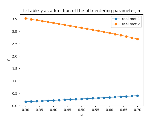
For this general case the coefficient of the term are . As observed in Fig. 1, the real roots of this expression vary only weakly with . Via the binomial series, the leading error for the centered CN scheme is . For the off-centered case (11) this increases to , and the method is only first order accurate for , such that the accuracy degrades most rapidly large eigenvalues and time steps.
Geophysical systems
This article considers two different geophysical systems, the two dimensional rotating shallow water equations on the sphere, and the three dimensional compressible Euler equations on both spherical and planar geometry. The rotating shallow water equations are a widely used prototypical model of geophysical phenomena on account of their capacity to represent both fast and slow nonlinear dynamics due to gravity and Rossby waves respectively. In the present case, comparing CN and RoW schemes for the rotating shallow water equations allows us to benchmark the allowable time step and conservation properties of these methods for the case of a very simple approximate Jacobian at low mach-number. The results for both the RoW and CN simulations will be somewhat sensitive to the choices made in the approximation of the Jacobian, so applying these methods to model configurations with different spatial discretisations and dynamics will help to determine commonalities between the results.
The rotating shallow water equations
The two dimensional rotating shallow water equations are given for the velocity and the fluid depth as
| (13a) | |||||
| (13b) | |||||
where is the Coriolis term due to the earth’s rotation, is (constant) gravity, is the mass flux, is the Bernoulli potential and is the potential vorticity. For a mean fluid depth much greater than the variations in and for spatial and temporal scales consistent with the earth’s rotation, the above system may be solved using a constant in time approximate Jacobian of the form [Baueret.al.(2018), 32, 17]
| (14) |
where is the Coriolis operator and is the gradient operator (for which the divergence operator is assumed to be its adjoint assuming periodic boundary conditions). The approximate Jacobian above omits non-linear terms associated with both mass and momentum transport, and instead assumes a linearisation around a state of constant mean fluid depth, planetary rotation and gravitational potential. Note that for the 3D compressible Euler equations described in the proceeding section, the presence of a complex and varying thermodynamic profile and acoustic modes means that the approximate Jacobian must be periodically reassembled, and incorporate additional terms not required for the shallow water case at low Mach number.
The shallow water equations consist of only prognostic equations for which is the full state vector and there is no vector of algebraic constraints. Note the use of subscripts, , to denote discrete representations of solution variables and forcing terms defined within an appropriate finite element subspace. In order to derive the discrete variational form of the equations from the continuous system (13) via the Galerkin method, one approximates the solution variables , by finite element trial functions which span the discrete equivalent of the and spaces respectively, and then multiples the momentum and continuity equations by test functions of the same form (applying integration by parts to derive a weak gradient of ). The discrete forms of , and are also determined via Galerkin projections at each nonlinear iteration into the discrete subspaces of , and respectively. See the above references for the specific definition of these operators using a mixed finite element discretisation of the rotating shallow water equations.
The 3D compressible Euler equations
While the rotating shallow water equations are a useful system for studying the suitability of numerical methods for representing gravity waves and barotropic turbulence, to fully capture the dynamics of a dry atmosphere at both planetary and non-hydrostatic scales, we also study RoW time integration for the 3D compressible Euler equations under the shallow atmosphere approximation, given for the velocity , density , potential temperature and Exner pressure as [21, 20, 14, 16] as
| (15a) | |||||
| (15b) | |||||
| (15c) | |||||
| (15d) | |||||
where is the vertical coordinate, and are the specific heats at constant pressure and volume respectively, is the reference surface pressure and is the ideal gas constant. The velocity transport term is expressed in (15a) in vector invariant form as . This form has the desirable property that the rotational and potential components of the flow are treated as separate terms. For the appropriate choice of finite element spaces for these terms, we can ensure that there is no spurious projections between rotational and divergence components of the flow in the discrete form [3]. As an alternative we may also express this term in advective form as . We will investigate both forms in the proceeding section.
Unlike the shallow water system, the compressible Euler equations contain an algebraic equation in the form of the ideal gas law (15d), such that the prognostic variables are given as and the diagnostic variable as . Via block factorisation of the coupled system (and approximate lumping of the non-diagonal velocity space mass matrix) one may derive a non-singular Helmholtz equation for the solution of [20], or alternatively the density weighted potential temperature if this is used as a prognostic variable instead of [14]. Consequently any RoW method used to solve the above system as a Helmholtz problem, either directly or as a preconditioner, should also be applicable to index-2 PDAEs.
One possible approximate Jacobian for the above system, which results in a Helmholtz problem for the Exner pressure via repeated Schur complement decomposition [21, 20] is given as
| (16) |
where , and are reference profiles for the density, potential temperature and Exner pressure respectively, derived from the prognostic variables at the time of the Jacobian assembly. For a full description of these operators in the context of a conforming finite element discretisation with , , (where is the set of bases in the subspace of consisting of scalar functions that are continuous in the vertical dimension only) see [21].
Implementation of transport terms in LFRic
In order to allow for longer time steps in LFRic with a fixed number of iterations, the mass and temperature transport terms in the right hand sides of (15) (and the velocity when in advective form) are evaluated explicitly at each nonlinear iteration over a series of smaller CFL dependent sub-steps using a transport velocity . Expressing the generalised transport operator at iteration as for , where for is the discrete form of the flux form transport operator (15b), and otherwise this is the material form transport operator (15c), the sub-stepped explicit transport is given as:
| (17a) | ||||
| (17b) | ||||
| (17c) | ||||
where , are the coefficients and weights respectively for the explicit Runge-Kutta substep . For the CN scheme a time centered velocity is used for the transport as . For the RoW scheme we cannot use a time centered velocity, owing to the specific reconstruction of the state at iteration as given in (6). As such there are two possible formulations for the explicit transport in the context of the RoW scheme. The first is to avoid sub-stepping, and just use a single forward Euler step at the current state as . This approach is consistent with the RoW method (5), but is limited to time steps with small advective CFL numbers due to the absence of sub-stepping.
The second approach is to integrate the initial stage over the time level using the incremental solution for the velocity at RoW stage , as:
| (18a) | ||||
| (18b) | ||||
| (18c) | ||||
| (18d) | ||||
The first stage, is integrated in the same fashion as the CN scheme (17). If the velocity increment is small with respect to the full velocity from which the CFL is determined, then we may update the subsequent stages using only single forward Euler steps, which are cheap to compute. There is no requirement on the last stage, , that the increment here be computed using forward Euler, and so this increment may once again be sub-stepped if required.
The transported quantities used to compute the fluxes, , may be derived from the values in neighbouring cells using either a centered or an upwinded reconstruction (which smoothes out oscillations via the dissipation of higher moments such as energy). We will explore the implications of both centered and upwinded fluxes in Sections Stability with centered transport terms and Performance with upwinded transport terms respectively.
Results
Rotating shallow water: shear flow instability on the sphere
We compare the results of four iterations of the Crank-Nicolson discretisation (CN4) to a variety of four stage RoW schemes in terms of both stable time step and energetic profiles for a standard shear flow instability test case on the sphere [5], run for 12 days so as to ensure that the schemes remain stable with the specified time step for a mature turbulent state. No off-centering is applied to the CN4 scheme, as is often done to increase stability at the expense of a reduced order of accuracy, however this is explored for the 3D compressible Euler equations in the proceeding section. The various RoW schemes are detailed in Table I.
| Scheme | Reference | Index | Stability |
|---|---|---|---|
| ROS34PW2 | [24] | 1 | |
| ROS34PW3 | [24] | 1 | |
| ROSI2Pw | [25] | 2 | , |
| ROSI2PW | [25] | 2 | |
| ROS34PRW | [22] | 2 | |
| ROS3PRL2 | [23, 12] | ||
| ROWDAIND2 | [Lubich(1990)] | 2 |
In each case the same conforming finite element method is applied for the spatial discretisation [15, 17], using third order finite elements on each panel of the cubed sphere for an average grid spacing of . The non-linear potential enstrophy cascade to grid scales is stabilised via the anticipated potential vorticity method [SadournyandBasdevant(1985)] with an upwinding parameter of , and energy is exactly conserved by the spatial discretisation. The mixed finite element discretisation used here has the same compatibility relations as in the LFRic model [21], but with polynomials two degrees higher than those used to solve the 3D compressible Euler equations in the proceeding section. The shallow water model also differs in its representation of the transport terms, which like all other terms are evaluated instantaneously as per (5), and not explicitly as in (17). The shallow water model uses 6 point Gauss-Lobatto-Legendre quadrature. While this is exact for order polynomials, the Jacobian transformation used to represent the surface of the sphere uses trigonometric functions, which cannot be exactly integrated at any order. Consequently there will be some small aliasing errors present, which may also affect the solver convergence and stability.
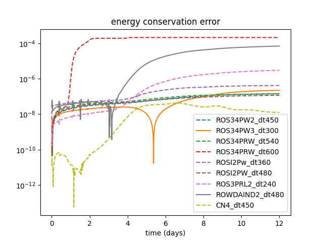
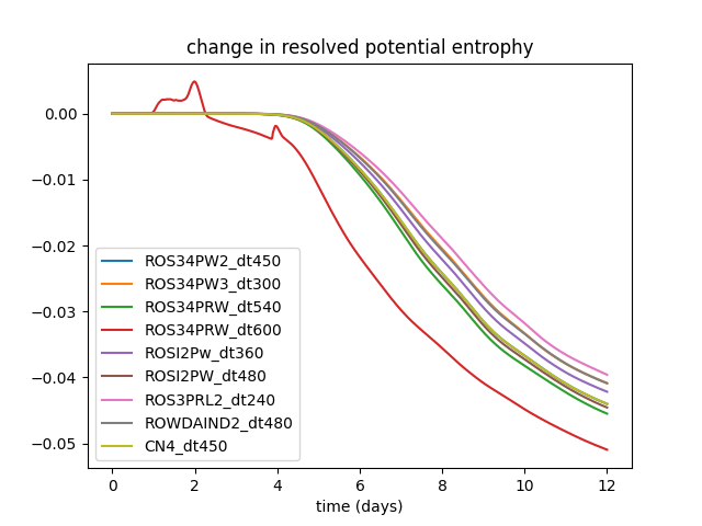
Figure 2 shows the normalised energy and potential enstrophy conservation errors for the different four-stage RoW and the CN4 scheme for the shear flow instability test case on the sphere. These are computed by globally integrating the total energy and potential enstrophy over the domain as
| (19a) | ||||
| (19b) | ||||
where the discrete form of the potential vorticity, , can be found in [Baueret.al.(2018), 17].
For the energy conservation error plot the solid lines corresponding to the ROS34PW3 and ROWDAIND2 schemes indicate a long time energy growth, so that the solution will ultimately become unstable. For the rest of the schemes , dashed lines indicate long time energy decay and hence stability. Of all the schemes, one in particular allows for stable simulation using significantly longer time steps, ROS34PRW [22]. Some care must be taken however, as while this scheme is stable for time steps of up to 600 seconds, at these long times the shear flow instability occurs at the incorrect wave-number, perhaps due to dispersion errors in the representation of the gravity waves which trigger the instability. This is also observed in the potential enstrophy conservation error, which exhibits an anomalous bump as the dynamics transition to the incorrect wave number. This problem is not observed and the dynamics evolve correctly for a time step of 540 seconds for the ROS34PRW scheme, which is still longer than the maximum stable time step of the CN4 scheme at 450 seconds. The potential enstrophy conservation error is broadly representative of the richness of the turbulence present in the solution. These errors broadly correlate with the length of the time steps for the different schemes, with the schemes with smaller stable time steps, such as ROS3PRL2 exhibiting the smallest potential enstrophy conservation error and the ROS34PRW the greatest.
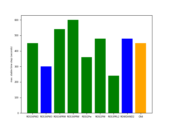
The maximum stable time steps are more clearly observed in the bar chart in Fig. 3. Here the schemes that exhibit positive energy error growth are given in blue, while the schemes that are long time stable are in green. The CN4 scheme is given as a reference in orange. The CN4 scheme is somewhere in the middle in terms of maximum stable time step, with several RoW schemes allowing for longer time steps. The ROS34PRW scheme is presented twice, once for its maximum stable time step of 600 seconds, and once for its maximum physically correct time step of 540 seconds.
The maximum stable time step was also investigated for the CN scheme at convergence. This was found to be the same as for four iterations (450 seconds), suggesting that the nonlinear errors after four iterations are well resolved with respect to other sources of error, such as approximations made in the form of the Jacobian and inexact spatial integration as mentioned above.
3D compressible Euler: baroclinic instability on the sphere
The RoW integrators are compared against the CN scheme for the 3D compressible Euler equations at planetary scales using a standard test case for a baroclinic wave triggered by a velocity perturbation in an otherwise geostrophically and hydrostatically balanced atmosphere [29] on z-levels as used in the LFRic model. We compare the schemes in two different contexts, firstly in terms of stability and energetics for a centered reconstruction of the fluxes in the transport terms, which minimises the amount of internal dissipation within the model in order to highlight differences in the representation of dynamics between the schemes. Secondly we compare the schemes in terms of computational performance using upwinded fluxes in order to damp internal oscillations and allow for longer time steps.
Stability with centered transport terms
The schemes are compared at two different spatial/temporal resolutions C48; lowest order elements (, ) and C96; lowest order elements (, ), both using 30 vertical levels. In the context of the mixed finite element spatial discretisation used here, lowest order elements refer to piecewise constant Exner pressure and density in each element, velocities that are piecewise linear in the normal direction and piecewise constant in the tangent directions, and a potential temperature that is piecewise linear in the vertical direction and piecewise constant in the horizontal directions [21]. No external dissipation was used in these simulations, so in all cases the solution ultimately becomes unstable. By avoiding the use of external damping terms we are better able to compare the internal stability of the different time integration schemes. In order to maintain the stability of the CN4 scheme, this was run with the potential temperature transport term in the Jacobian, in (The 3D compressible Euler equations), damped in favor of the future time level, such that the factor of in (2) for this term only (and is kept as for all other terms). In all cases a simple forward Euler integration of the transport terms (17) was applied for a single sub-step at each iteration (with this being evaluated at the current time level for the RoW schemes). This ensures that the transport terms are evaluated instantaneously so as to be faithful to the original CN and RoW formulations.
The globally integrated kinetic (horizontal and vertical), potential and internal energies are computed respectively over the full domain at each time step as
| (20a) | ||||
| (20b) | ||||
| (20c) | ||||
| (20d) | ||||
where and are the horizontal and vertical velocities respectively, and gravity, , is assumed to be constant. The kinetic energy is separated into its horizontal and vertical components. This makes the evolution of the vertical component, which is significantly smaller than the horizontal component in most atmospheric configurations, more visible, and helps to illustrate differences in the evolution of the baroclinic instability between the different schemes.
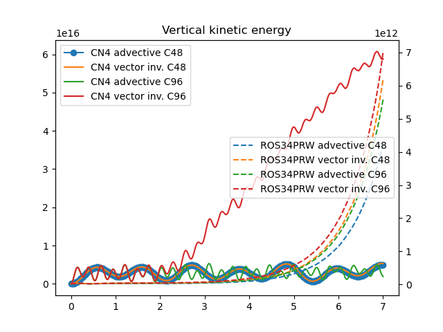
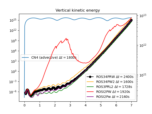
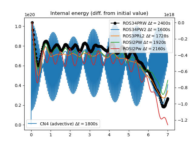
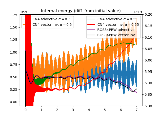
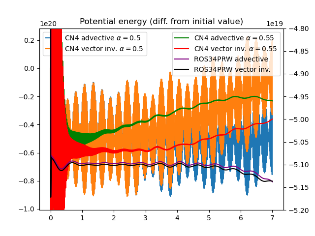
As observed in the internal and potential energy evolution as shown in Fig. 4 the CN4 schemes exhibit a spurious oscillation on a time scale of , that is not present for the ROS34PRW scheme, which show a much smaller oscillation on a time scale of approximately 12 hours independent of time step size. This oscillation is consistent with the temporal oscillation observed in the horizontal kinetic energy in Fig. 5, and is perhaps a result of inexact hydrostatic balance in the initial condition that is quickly damped by the L-stable RoW scheme, but not by the CN4 scheme. The growth of the baroclinic instability is observed in the evolution of the vertical kinetic energy for the ROS34PRW scheme also in Fig. 5. This result is consistent with previous observations using a high order mixed finite element model with horizontally explicit/vertically implicit time stepping and exact energy conservation for the implicit vertical solve [14]. However for the CN4 scheme, this signal is insignificant with respect to the vertical kinetic energy signal associated with the internal-potential buoyancy oscillation (left axis), which at Joules is approximately times greater than the vertical kinetic energy associated with the baroclinic instability, as observed for the ROS34PRW scheme on the right axis.
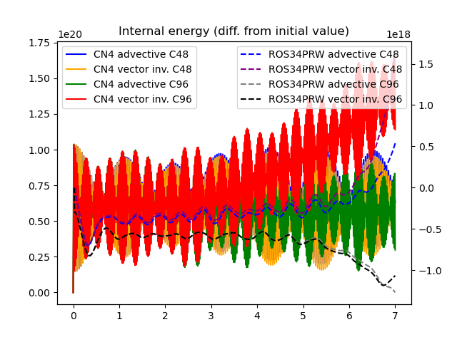
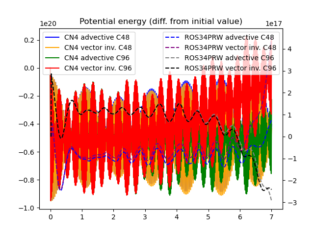
This persistence of oscillation is perhaps a consequence of the neutral stability of the CN4 temporal scheme with . Using the L-stable values described for the four iteration CN scheme in Section Quasi-Newton Crank-Nicolson time discretisation as a Rosenbrock-Wanner scheme, this oscillation is suppressed, however the simulation is rapidly observed to be unstable (and so is not presented here). An alternative, stable method for suppressing this oscillation is to off-center the CN scheme in favor of the new time level (by a factor of ), however this leads to a degradation of accuracy. Results using this off-centering for the CN4 scheme will be presented below.
In terms of the internal and potential energy evolution, only the ROS34PRW scheme at the C96 resolution gives observably consistent results with respect to those previously published using an exact energy conserving vertical integrator [14], where both the internal and potential energy trend downward with time in order to balance the growth in kinetic energy due to the baroclinic instability.
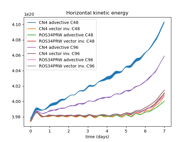
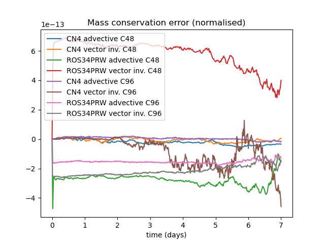
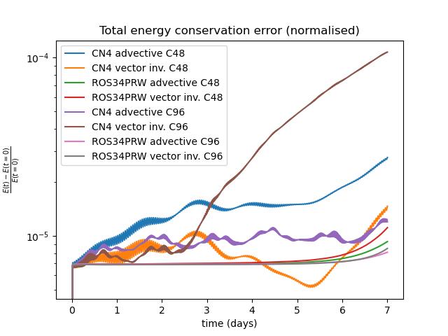
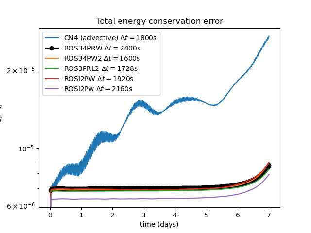
Normalised mass conservation errors for the different configurations are presented in Fig. 6. Since in all cases the mass continuity equation represented by a flux form finite volume scheme, the conservation errors are all close to machine precision. However the RoW configurations manifest errors an order of magnitude greater than those for the CN scheme. The total energy conservation error is also given in Fig. 6, where it is observed that the CN4 scheme has significantly greater total energy growth than the ROS34PRW scheme at the same resolution. In particular, the vector invariant form of the CN4 integrator at C96 resolution exhibits a rapid growth of the energy conservation error that suggests the onset of numerical instability. This is reflected in the fact that this configuration requires two forward Euler sub-steps for the transport terms at each nonlinear iteration, whereas each of the other configurations requires just a single forward Euler sub-step for the transport due to the moderate velocity magnitudes in comparison to the CFL number in this test case. The instability observed for the vector invariant form of the CN4 discretisation is perhaps due to this configuration being closer to a neutrally stable state than the more overtly damped advective form (or the L-stable vector invariant ROS34PRW scheme), and so is more susceptible to instability as potentially triggered by the high frequency temporal oscillation observed for the CN4 scheme in Fig. 4.
While the energetic results presented here are revealing in terms of how the different time stepping schemes effect the internal dynamics, we note that these errors may be small compared to those introduced by external forcing terms such as parameterisations of physical processes and the coupling to other model components.
The lowest level potential temperature and Exner pressure are shown at day 7 for the C96 resolution in Figs 7, 8 and 10, 9 respectively for the CN4 and ROS34PRW schemes. For the Exner pressure these are presented as a normalised difference with respect to the vector invariant ROS34PRW scheme. While the results are in broad agreement for the potential temperature, there is a spurious meridional variation in surface pressure observed for the advective CN4, however this variation is small with respect to differences in the solution for the baroclinic wave. Additionally, spurious small scale oscillations are observed for the CN4 vector invariant scheme.


Meridional biases are also observed for the CN4 scheme in both advective and vector invariant forms for the lowest level three dimensional divergence as presented in Fig. 12. These biases are an order of magnitude greater than the divergence associated with the baroclinic instability. The divergence resulting from the baroclinic process is clearly observed without such biases for the ROS34PRW formulations in Fig. 11.


We also compare the energetic profiles for the various RoW schemes studied for the shallow water equations in Section 3.1. for the C96 resolution in Fig. 13. These are presented in vector invariant form for the largest time steps for which the different schemes were observed to be stable and convergent using centered flux reconstructions. We exclude results for the ROWDAIND2 and ROS34PW3 schemes, as these were observed to be rapidly unstable, which is consistent with the shallow water results, where these schemes produced a positive growth in energy as seen in Figs. 2, 3. In the case of the ROS34PW3 scheme, this is perhaps a consequence of the fact that it is only A-stable and not L-stable, meaning that the amplification factor as discussed in Section Quasi-Newton Crank-Nicolson time discretisation as a Rosenbrock-Wanner scheme does not go to zero as the eigenvalues approach infinity.
In all cases the RoW schemes exhibit lower energy conservation error than the CN4 scheme (in advective form). When comparing the vertical kinetic energy profiles, we see that the RoW schemes all exhibit a growth associated with the baroclinic instability that is consistent with previous results [14], and that is two orders of magnitude smaller than that associated with the spurious oscillation of the CN4 scheme. The ROS34PRW scheme is observed to be stable and convergent at a time step of , which is approximately 30% longer than the maximum observed stable time step for the CN4 scheme at . This result is consistent with those observed for the shallow water experiments in Section Rotating shallow water: shear flow instability on the sphere, where the ROS34PRW was observed to be stable for time steps 20% longer than the CN4 scheme. In all cases the configurations at the maximum observably stable time step required two forward Euler transport sub-steps for the majority of the simulation time.
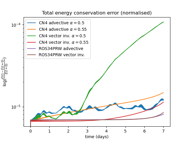
One method of suppressing the fast oscillation observed for the CN4 scheme is to off-center the time discretisation in favor of the future time level , as given in (11), as this ensures that the time discretisation is no longer neutrally stable. The downside of this approach is that it degrades the formal accuract of the method. In Fig. 14 we compare the internal and potential energy and energy conservation error profiles for the CN4 scheme using centered () and off-centered () time discretisations with respect to the ROS34PRW scheme for the C96 resolution.
As observed, the off-centering does ultimately suppress the spurious oscillation, such that it is of smaller amplitude that the long time signal after approximately 1-2 days. However the energy conservation errors are still greater than for the ROS34PRW scheme, which exhibits no such oscillation even at short times. Even with the off-centered time discretisation, the CN4 schemes still exhibit spurious growth in the potential and internal energies, which should actually be decreasing to balance the growth in kinetic energy of the baroclinic instability as is the case for the ROS34PRW scheme, and also for previous results using an integrator that exactly conserves energy for the vertical dynamics [14].
We also compare the lowest level divergence for the off-centered advective and vector invariant CN4 schemes in Fig. 15. While the meridional biases are reduced somewhat compared to those observed for the centered formulations in Fig. 12, they are still present and greater than the physical divergence of the baroclinic instability, which is observed without such bias for the ROS34PRW scheme in Fig. 11.


Performance with upwinded transport terms
In order to compare the computational performance of the different schemes we use an upwinded reconstruction of the fluxes in the transport terms, which introduces additional internal dissipation that allows for longer time steps. We focus on the advective form of the momentum equation such that dissipation is applied to the momentum transport as well. For the CN scheme we use a value of in the approximate Jacobian for both the density and potential temperature operators in (The 3D compressible Euler equations), in order to over-relax the solution of these transport terms, while keeping a value of in the momentum equation terms.
The transport terms are sub-stepped using a strong-stability preserving order Runge-Kutta (SSP-RK3) scheme at each sub-step, and for the RoW schemes this was applied using the velocity increments for the transport velocity as in (18) (with single forward Euler steps at the second and third stages and sub-stepped SSP-RK3 on the first and fourth stages).
The CN scheme was tested in three different configurations, firstly using four iterations with the transport terms applied on the first and third stages (two-outer/two-inner iterations; 2o2i), secondly with the transport applied at each of the four stages, as in Section Stability with centered transport terms (four-outer/one-inner iteration; 4o1i), and thirdly using three iterations with the transport at every stage (three-outer/one-inner iteration; 3o1i). The four iteration schemes were also run using the L-stable CN scheme described in Section Quasi-Newton Crank-Nicolson time discretisation as a Rosenbrock-Wanner scheme. We also explored the three stage RoW method in [Jahnet.al.(2015)], however this could not be run stably.
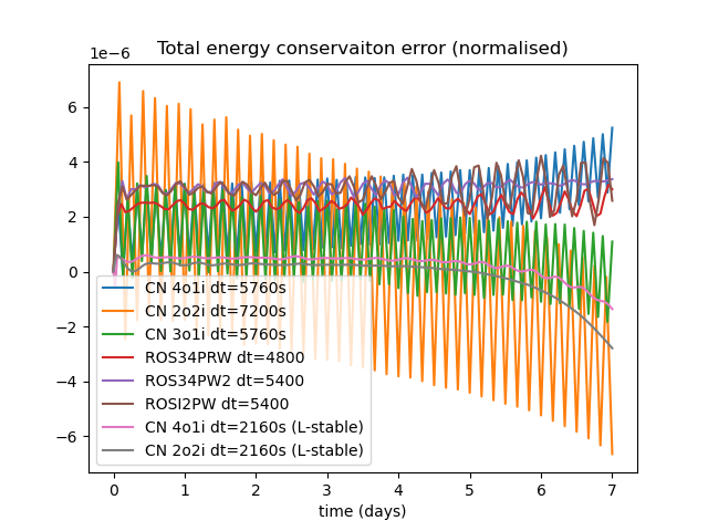
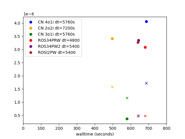
The wall times for 7 days of simulation at the C96 resolution for the upwinded configurations are listed in Table II. The CN 2o2i and CN 3o1i schemes allowed for the fastest time to solution, ahead of the RoW schemes, with the CN 4o4i behind owing to the application of the sub-stepped SSP-RK3 transport at each nonlinear iteration. The L-stable () CN schemes were the least efficient, owing to the severe time step restriction of these schemes. The L-stable CN schemes were also explored, however these were not stable even with shorter time steps of .
| Scheme | (seconds) | Wall time (seconds) |
|---|---|---|
| CN 4o1i | 5760.0 | 686.82 |
| CN 2o2i | 7200.0 | 496.26 |
| CN 3o1i | 5760.0 | 578.50 |
| ROS34PRW | 4800.0 | 680.85 |
| ROS34PW2 | 5400.0 | 644.05 |
| ROSI2PW | 5400.0 | 640.51 |
| CN 4o1i () | 2160.0 | 1861.59 |
| CN 2o2i () | 2160.0 | 1757.60 |
In order to investigate the energetics of these upwinded configurations the total energy conservation errors are given in Fig. 16. As for the centered schemes, the upwinded CN schemes exhibit a temporal oscillation with a frequency of , which trends towards instability for the CN 4o1i scheme. To a lesser degree this oscillation is also present for the RoW schemes, suggesting that their L-stable nature is insufficient to fully damp these internal oscillations in advective form with large time steps. Only the L-stable CN schemes appear to be free of this oscillation. This figure also shows the absolute value of the energy conservation error (averaged over the last two time steps to remove the oscillation) and the absolute value of the maximum lowest level divergence at day 7 for the different schemes as a function of time to solution. While the CN 2o2i scheme is the most efficient, it also suffers from larger conservation and divergence errors than the CN 3o1i scheme. The RoW schemes have the smallest divergence errors but relatively large energy conservation errors, suggesting that these schemes are somewhat under-damped in advective form. The L-stable CN schemes are not shown, owing to their significantly larger wall times.
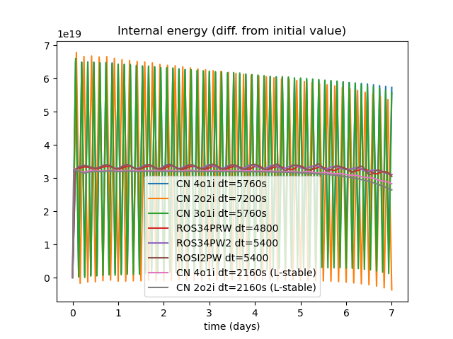
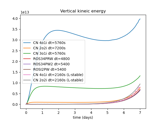
The internal energy as a function of time for the upwinded schemes is given in Fig. 17. Unlike for the centered schemes in Fig. 4, the upwinded CN schemes all exhibit the correct downward trend in internal (and potential, not shown) energy in order to balance out the growth in kinetic energy of the baroclinic instability. This figure also shows the vertical kinetic energy as a function of time. While the error observed for the CN schemes with centered fluxes in Fig. 5 is not present for the upwinded schemes, there is still a large error observed for the CN 4o1i and CN 3o1i schemes, with the CN 2o2i and L-stable CN schemes yielding results consistent with the RoW schemes.
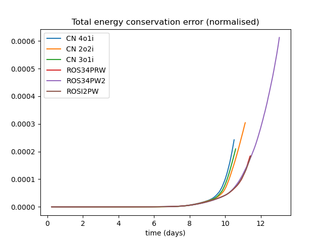
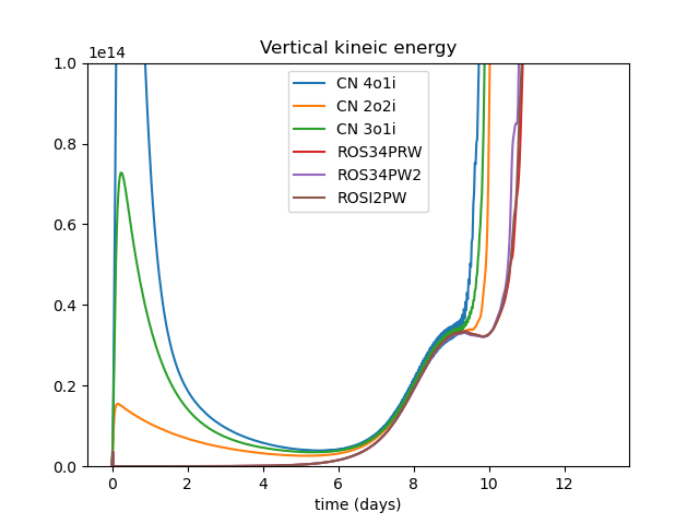
Finally, we also show the total energy conservation errors and vertical kinetic energy for the upwinded CN and RoW configurations with a fixed time step of in Fig. 18. In all cases the the RoW schemes run for somewhat longer than the CN schemes before also ultimately going unstable due to insufficient damping. There is also a large perturbation in the initial vertical kinetic energy for the CN schemes due to the internal oscillations that is not present for the RoW schemes.
3D compressible Euler: warm bubble on the plane
While the baroclinic instability test case is a good measure of the dynamics at planetary scales, the non-hydrostatic and compressible dynamics are negligible. Consequently we also compare the different schemes for a high resolution 3D warm bubble test case [6, 21, 14, 16] for which these effects are significant. The model is configured with an initial state of constant density in hydrostatic balance in a three dimensional horizontally periodic box using lowest order elements with a uniform resolution of . The balanced state is overlaid with a small potential temperature perturbation, which rises and distorts over several minutes. We compare the schemes using the advective form with upwinded flux reconstructions, as in Section Performance with upwinded transport terms, with the transport terms applied as in (18) for the RoW schemes. Unlike for the baroclinic test case, monotone transport is applied for the potential temperature.
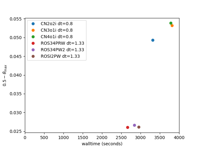
Table III details the wall times and errors in the maximum value of the potential temperature, at 400s for the different schemes. In contrast to the baroclinic test case, here the RoW schemes allow for longer time steps and shorter times to solution. Despite the application of longer time steps, the errors in are also smaller for the RoW schemes. The ability to run the RoW schemes for the longer time steps than the CN schemes at the non-hydrostatic scale is perhaps due to the L-stable nature of the RoW schemes, and their corresponding capacity damp fast oscillations associated with initial hydrostatic imbalance and acoustic modes.
| Scheme | (seconds) | Wall time (seconds) | error in |
|---|---|---|---|
| CN 4o1i | 0.8 | 3780.32 | 0.053841 |
| CN 2o2i | 0.8 | 3318.10 | 0.049282 |
| CN 3o1i | 0.8 | 3810.97 | 0.053183 |
| ROS34PRW | 1.33 | 2661.80 | 0.026015 |
| ROS34PW2 | 1.33 | 2841.93 | 0.026591 |
| ROSI2PW | 1.33 | 2955.06 | 0.026119 |
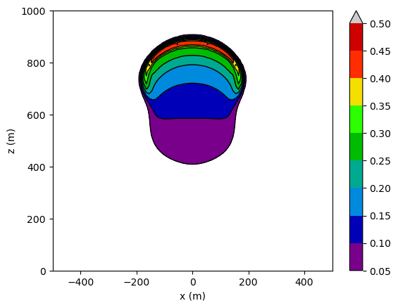
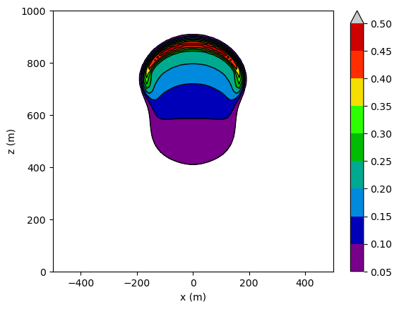
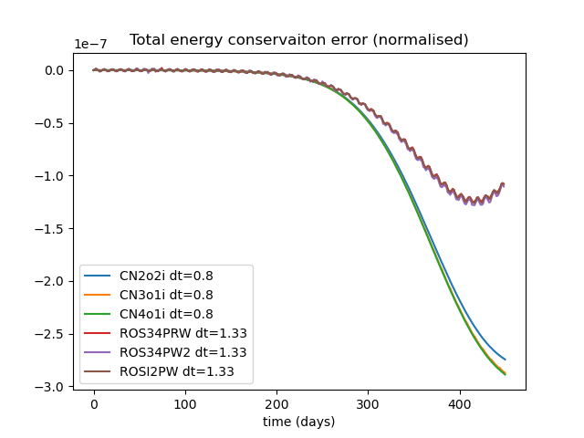
The less diffusive nature of the RoW schemes is also observed in the potential temperature cross sections at 400s in Fig. 19, which compares the most accurate RoW (ROS34PRW) and CN (2o2i) schemes. The normalised energy conservation errors are presented in Fig. 20. While the CN schemes display a continued decay in total energy, this begins to increase as the bubble ascends for the RoW schemes. This tracks closely with the internal energy evolution of the different schemes (not shown), which also show a steady decrease for the CN schemes and an uptick for the RoW schemes. Previous results [14] using an exact energy conserving vertical integrator suggest that while the potential energy should exhibit a negative trend as the bubble ascends, the mean internal energy (aside from the fast oscillation) should stay relatively constant, so from this we infer that the RoW schemes are more physically realistic.
This figure also shows a scatter plot detailing the errors in at 400s as a function of time to solution at maximum stable time step, as also presented in Table III. The RoW schemes are both the most efficient as well as the most accurate by this measure. This is in contrast to the similar plot in Fig. 16, where the CN2o2i and CN3o1i schemes are the most efficient for the baroclinic wave test case.
Conclusions
This article compares the results for a collection of four stage RoW time integrators with an approximate Jacobian as a substitute for a CN time discretisation for the solution of geophysical systems at planetary and non-hydrostatic scales. Comparisons are made in terms of both energetics for a vector invariant formulation with centered fluxes, in order to minimise the amount of internal dissipation, and also in terms of time to solution for an advective formulation with upwinded fluxes, in order to introduce internal dissipation and allow for longer time steps and shorter wall times.
For the vector invariant form with centered fluxes, the best performing RoW schemes allow for longer time steps than the four iteration CN scheme for both the shallow water and 3D compressible Euler equations at planetary scales. Also for the 3D compressible Euler equations the RoW schemes are free of the spurious high frequency oscillations, divergence errors and upward trends in internal and potential energy that are present for the CN scheme, even with off-centering in the temporal discretisation.
For the upwinded advective formulations the results are more mixed, with the CN 2o2i scheme (four iterations with transport terms applied on the first and third iterations) allowing for the longest time steps and shortest wall times for the planetary scale baroclinic instability test case, and the RoW schemes allowing for the longest time steps and shortest wall times for the non-hydrostatic rising bubble test case. The other CN schemes (3o1i and 4o1i) exhibited large errors in the vertical kinetic energy despite also being more performant than the RoW schemes at planetary scales, and at non-hydrostatic scales the RoW methods were also less diffusive than the CN schemes as well as being more performant.
We also introduce a new temporal formulation of the transport terms for the RoW schemes, based on the transport of solution increments at subsequent stages, that allowed for the efficient implementation of the RoW methods in advective form. An L-stable variant of the four stage CN scheme was also derived. While this effectively cleaned up the spurious oscillations of the CN scheme in advective form, it was shown to be stable only for small time steps that limited its performance, and was not observed to be stable with centered fluxes.
Finally, we note that the results of this study will be somewhat sensitive to the choice of approximations made in the evaluation of the Jacobian. While modifications to the Jacobian approximation for the shallow water model yielded little variation in results, there may be more variation for LFRic, for which the presence of acoustic modes and complex thermodynamics may introduce additional sensitivity.
Acknowledgments
David Lee would like to thank Drs. Gary Dietachmayer and Nigel Wood for their helpful comments and insights on an early version of this manuscript, and Drs. Thomas Melvin and Ben Shipway for their constructive comments and advice. David is also grateful to the three anonymous reviewers, all of whom provided helpful feedback that improved this manuscript.
The author acknowledges no conflict of interest.
CRediT authorship contribution statement
David Lee: Conceptualisation, data curation, formal analysis, investigation, methodology, project administration, software, validation, visualisation, writing: reviewing and editing.
References
- [1] W Bauer and C J Cotter. Energy-enstrophy conserving compatible finite element schemes for the rotating shallow water equations with slip boundary conditions. J. Comp. Phys., 373:171–187, 2018.
- [2] D S Blom, P Birken, H Bijl, F Kessels, A Meister, and A H van Zuijlen. A comparison of Rosenbrock and ESDIRK methods combined with iterative solvers for unsteady compressible flows. Adv. Comput. Math., 42:1401–1426, 2016.
- [3] C J Cotter and J Shipton. Mixed finite elements for numerical weather prediction. J. Comp. Phys., 231:7076–7091, 2012.
- [4] S Deparis, M O Deville, F Menghini, L Pegolotti, and A Quarteroni. Application of the Rosenbrock methods to the solution of unsteady 3D incompressible Navier-Stokes equations. Computers & Fluids, 179:112–122, 2019.
- [5] J Galewsky, R K Scott, and L M Polvani. An initial-value problem for testing numerical models of the global shallow water equations. Tellus, 56A:429–440, 2004.
- [6] F X Giraldo, J F Kelly, and E M Constantinescu. Implicit-explicit formulations of a three-dimensional nonhydrostatic unified model of the atmosphere (NUMA). SIAM J. Sci. Comput., 35:B1162–B1194, 2013.
- [7] E Hairer and G Wanner. Solving ordinary differential equations. II: Stiff and differential-algebraic problems, Springer Series in Computational Mathematics, second ed., vol. 14. Springer-Verlag, Berlin, 1996.
- [8] M Jähn, O Knoth, M König, and U Vogelsberg. ASAM v2.7: a compressible atmospheric model with a Cartesian cut cell approach. Geosci. Model Dev., 8:317–340, 2015.
- [9] V John and J Rang. Adaptive time step control for the incompressible Navier–Stokes equations. Comput. Methods Appl. Mech. Engrg., 199:514–524, 2010.
- [10] V John, G Matthies, and J Rang. A comparison of time-discretization/linearization approaches for the incompressible Navier–Stokes equations. Comput. Methods Appl. Mech. Engrg., 195:5995–6010, 2006.
- [11] C Kennedy and M H Carpenter. Diagonally implicit Runge-Kutta methods for stiff ODEs. Appl. Numer. Math., 146:221–244, 2019.
- [12] J Lang and D Teleaga. Towards a fully space-time adaptive FEM for magnetoquasistatics. IEEE Trans. Magn., 44:1238–1241, 2008.
- [13] J Lang and J G Verwer. W-methods in optimal control. Numer. Math., 124:337–360, 2013.
- [14] D Lee. An energetically balanced, quasi-Newton integrator for non-hydrostatic vertical atmospheric dynamics. J. Comp. Phys., 429:109988, 2021.
- [15] D Lee and A Palha. A mixed mimetic spectral element model of the rotating shallow water equations on the cubed sphere. J. Comp. Phys., 375:240–262, 2018.
- [16] D Lee and A Palha. Exact spatial and temporal balance of energy exchanges within a horizontally explicit/vertically implicit non-hydrostatic atmosphere. J. Comp. Phys., 440:110432, 2021.
- [17] D Lee, A Martin, C Bladwell, and S Badia. A comparison of variational upwinding schemes for geophysical fluids, and their application to potential enstrophy conserving discretisations in space and time. arXiv:2203.04629, 2022.
- [18] X Liu, Y Xia, H Luo, and L Xuan. A comparative study of Rosenbrock-type and implicit Runge-Kutta time integration for discontinuous Galerkin method for unsteady 3D compressible Navier–Stokes equations. Commun. Comput. Phys., 20:1016–1044, 2016.
- [19] C Lubich and M Roche. Rosenbrock methods for differential-algebraic systems with solution-dependent singular matrix multiplying the derivative. Computing, 43:325–342, 1990.
- [20] C Maynard, T Melvin, and E H Müller. Multigrid preconditioners for the mixed finite element dynamical core of the LFRic atmospheric model. Q. J. R. Meteorol. Soc., 146:3917–3936, 2020.
- [21] T Melvin, T Benacchio, B Shipway, N Wood, J Thuburn, and C Cotter. A mixed finite-element, finite-volume, semi-implicit discretisation for atmospheric dynamics: Cartesian geometry. Q. J. R. Meteorol. Soc., 145:1–19, 2019.
- [22] J Rang. A new stiffly accurate Rosenbrock–Wanner method for solving the incompressible Navier-Stokes equations. In Ansorge R, Bijl H, Meister A, and Sonar T, editors, Recent Developments in the Numerics of Nonlinear Hyperbolic Conservation Laws, 120, pages 301–315. Springer Verlag, Heidelberg, Berlin, 2012.
- [23] J Rang. Improved traditional Rosenbrock–Wanner methods for stiff ODEs and DAEs. J. Comput. Appl. Math., 286:128–144, 2015.
- [24] J Rang and L Angermann. New Rosenbrock W-methods of order 3 for partial differential algebraic equations of index 1. BIT Numer. Math., 45:761–787, 2005.
- [25] J Rang and L Angermann. New Rosenbrock methods of order 3 for PDAEs of index 2. Adv. Differ. Eq. Control. Process., 1:193–217, 2008.
- [26] R Sadourny and C Basdevant. Parameterization of Subgrid Scale Barotropic and Baroclinic Eddies in Quasi-geostrophic Models: Anticipated Potential Vorticity Method. J. Atmos. Sci., 42:1353–1363, 1985.
- [27] B A Schmitt and R Weiner. Matrix-free W-methods using a multiple Arnoldi iteration. Appl. Numer. Math., 18:307–320, 1995.
- [28] P Tranquilli and A Sandu. Rosenbrock-Krylov methods for large systems of differential equations. SIAM J. Sci. Comput., 36:A1313–A1338, 2014.
- [29] P A Ullrich, T Melvin, C Jablonowski, and A Staniforth. A proposed baroclinic wave test case for deep- and shallow-atmosphere dynamical cores. Q. J. R. Meteorol. Soc., 140:1590–1602, 2014.
- [30] J G Verwer, E J Spee, J G Blom, and W Hundsdorfer. A second-order Rosenbrock method applied to photochemical dispersion problems. SIAM J. Sci. Comput., 20:1456–1480, 1999.
- [31] R Weiner, B A Schmitt, and H Podhaisky. ROWMAP—a ROW-code with Krylov techniques for large stiff ODEs. Appl. Numer. Math., 25:303–319, 1997.
- [32] G A Wimmer, C J Cotter, and W Bauer. Energy conserving upwinded compatible finite element schemes for the rotating shallow water equations. J. Comp. Phys., 401:109016, 2020.